US7419034B1 - V-type brake - Google Patents
V-type brake Download PDFInfo
- Publication number
- US7419034B1 US7419034B1 US11/808,837 US80883707A US7419034B1 US 7419034 B1 US7419034 B1 US 7419034B1 US 80883707 A US80883707 A US 80883707A US 7419034 B1 US7419034 B1 US 7419034B1
- Authority
- US
- United States
- Prior art keywords
- brake
- linkage
- link member
- pivot
- arm
- Prior art date
- Legal status (The legal status is an assumption and is not a legal conclusion. Google has not performed a legal analysis and makes no representation as to the accuracy of the status listed.)
- Expired - Fee Related
Links
Images


Classifications
-
- B—PERFORMING OPERATIONS; TRANSPORTING
- B60—VEHICLES IN GENERAL
- B60T—VEHICLE BRAKE CONTROL SYSTEMS OR PARTS THEREOF; BRAKE CONTROL SYSTEMS OR PARTS THEREOF, IN GENERAL; ARRANGEMENT OF BRAKING ELEMENTS ON VEHICLES IN GENERAL; PORTABLE DEVICES FOR PREVENTING UNWANTED MOVEMENT OF VEHICLES; VEHICLE MODIFICATIONS TO FACILITATE COOLING OF BRAKES
- B60T1/00—Arrangements of braking elements, i.e. of those parts where braking effect occurs specially for vehicles
- B60T1/02—Arrangements of braking elements, i.e. of those parts where braking effect occurs specially for vehicles acting by retarding wheels
- B60T1/06—Arrangements of braking elements, i.e. of those parts where braking effect occurs specially for vehicles acting by retarding wheels acting otherwise than on tread, e.g. employing rim, drum, disc, or transmission or on double wheels
-
- F—MECHANICAL ENGINEERING; LIGHTING; HEATING; WEAPONS; BLASTING
- F16—ENGINEERING ELEMENTS AND UNITS; GENERAL MEASURES FOR PRODUCING AND MAINTAINING EFFECTIVE FUNCTIONING OF MACHINES OR INSTALLATIONS; THERMAL INSULATION IN GENERAL
- F16D—COUPLINGS FOR TRANSMITTING ROTATION; CLUTCHES; BRAKES
- F16D55/00—Brakes with substantially-radial braking surfaces pressed together in axial direction, e.g. disc brakes
- F16D55/02—Brakes with substantially-radial braking surfaces pressed together in axial direction, e.g. disc brakes with axially-movable discs or pads pressed against axially-located rotating members
- F16D55/22—Brakes with substantially-radial braking surfaces pressed together in axial direction, e.g. disc brakes with axially-movable discs or pads pressed against axially-located rotating members by clamping an axially-located rotating disc between movable braking members, e.g. movable brake discs or brake pads
- F16D55/224—Brakes with substantially-radial braking surfaces pressed together in axial direction, e.g. disc brakes with axially-movable discs or pads pressed against axially-located rotating members by clamping an axially-located rotating disc between movable braking members, e.g. movable brake discs or brake pads with a common actuating member for the braking members
- F16D55/2245—Brakes with substantially-radial braking surfaces pressed together in axial direction, e.g. disc brakes with axially-movable discs or pads pressed against axially-located rotating members by clamping an axially-located rotating disc between movable braking members, e.g. movable brake discs or brake pads with a common actuating member for the braking members in which the common actuating member acts on two levers carrying the braking members, e.g. tong-type brakes
-
- F—MECHANICAL ENGINEERING; LIGHTING; HEATING; WEAPONS; BLASTING
- F16—ENGINEERING ELEMENTS AND UNITS; GENERAL MEASURES FOR PRODUCING AND MAINTAINING EFFECTIVE FUNCTIONING OF MACHINES OR INSTALLATIONS; THERMAL INSULATION IN GENERAL
- F16D—COUPLINGS FOR TRANSMITTING ROTATION; CLUTCHES; BRAKES
- F16D2121/00—Type of actuator operation force
- F16D2121/14—Mechanical
-
- F—MECHANICAL ENGINEERING; LIGHTING; HEATING; WEAPONS; BLASTING
- F16—ENGINEERING ELEMENTS AND UNITS; GENERAL MEASURES FOR PRODUCING AND MAINTAINING EFFECTIVE FUNCTIONING OF MACHINES OR INSTALLATIONS; THERMAL INSULATION IN GENERAL
- F16D—COUPLINGS FOR TRANSMITTING ROTATION; CLUTCHES; BRAKES
- F16D2125/00—Components of actuators
- F16D2125/18—Mechanical mechanisms
- F16D2125/58—Mechanical mechanisms transmitting linear movement
- F16D2125/68—Lever-link mechanisms, e.g. toggles with change of force ratio
Definitions
- This invention relates to a brake, and more particularly to a V-type brake for slowing down or stopping a wheel.
- a conventional V-type brake 2 is adapted for slowing down or stopping a wheel 1 , and includes a first brake arm 21 , a second brake arm 22 , a tube-fastening seat 23 connected pivotally to a free end 211 of the first brake arm 21 , a curved tube 24 fastened removably to the tube-fastening seat 23 , a brake cable 25 extending through the curved tube 24 and having an end fastened to a free end 221 of the second brake arm 22 , and a pair of brake shoes 26 disposed respectively on inner sides of the first and second brake arms 21 , 22 and pivotable into contact with the wheel 1 .
- the object of this invention is to provide a V-type brake for slowing down or stopping a wheel, which can be operated easily to allow for convenient removal or remounting of the wheel.
- a V-type brake of this invention is adapted to slow down or stop a wheel, and includes a pair of first and second brake arms, a brake cable assembly connected to a free end of the second brake arm, and a linkage.
- the linkage is connected pivotally to a free end of the first brake arm, and is interconnected between the free end of the first brake arm and the brake cable assembly in such a manner that the linkage is in a folded state.
- the linkage is operable to unfold so as to pivot the free ends of the first and second brake arms away from each other, thereby increasing the distance between brake shoes on the first and second brake arms for removal or remounting of the wheel.
- the operator can fold or unfold the linkage using only a single hand.
- the V-type brake can be operated with ease.
- FIG. 1 is a fragmentary exploded perspective view of a conventional V-type brake
- FIG. 2 is a front view of the conventional V-type brake
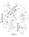
- FIG. 3 is a fragmentary exploded perspective view of the preferred embodiment of a V-type brake according to this invention.
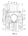
- FIG. 4 is a front view of the preferred embodiment
- FIG. 5 is a schematic top view of the preferred embodiment when a linkage is in a folded state
- FIG. 6 is a front view of the preferred embodiment when the linkage is in a semi-folded state, illustrating how a safety hook is removed from a first brake arm;
- FIG. 7 is a front view of the preferred embodiment when the linkage is in a semi-folded state, illustrating how a push plate is pushed upwardly;
- FIG. 8 is a front view of the preferred embodiment when the linkage is fully unfolded.
- the preferred embodiment of a V-type brake according to this invention is used to slow down or stop a wheel 6 , and includes a brake arm unit 3 , a brake cable assembly 4 , and a linkage 5 .
- the brake arm unit 3 includes a pair of first and second brake arms 31 , 32 each having a pivot end 311 , 321 connected pivotally to a frame body 7 , and a free end 312 , 322 .
- the first and second brake arms 31 , 32 are provided respectively with a pair of first and second brake shoes 33 , 34 on inner sides thereof in a known manner.
- the free ends 312 , 322 of the first and second brake arms 31 , 32 are biased to pivot away from each other in a known manner.
- the brake cable assembly 4 includes a tube-fastening seat 41 , a curved tube 42 , and a brake cable 43 .
- the tube-fastening seat 41 is generally U-shaped, and has a first end 411 connected to the linkage 5 , and a second end 412 for fastening removably the curved tube 42 in a known manner.
- the brake cable 43 extends through the curved tube 42 , and is fastened to the free end 322 of the second brake arm 32 in a known manner.
- the linkage 5 includes a first link member 51 , a second link member 52 , a push plate 53 , a safety hook 54 , a first pivot (A), a second pivot (B), and a third pivot (C).
- the first link member 51 includes two parallel link rods 511 , and has an end connected pivotally to the free end 312 of the first brake arm 31 by the first pivot (A).
- An end of the second link member 52 is connected pivotally to the first end 411 of the tube-fastening seat 41 by the second pivot (B).
- the other end of the first link member 51 is connected pivotally to the other end of the second link member 52 by the third pivot (C).
- the distance between the first and third pivots (A, C) is greater than that between the second and third pivots (B, C).
- the push plate 53 extends integrally from an end of the second link member 52 adjacent to the third pivot (C) in a direction away from the other end of the second link member 52 .
- the linkage 5 is in a folded state, as shown in FIG. 4 .
- the first pivot (A) is higher than the second pivot (B) and disposed between two parallel side walls ( 41 S)
- the second and third pivots (B, C) are in contact with the first brake arm 31
- the free end 312 of the first brake arm 31 is disposed between the first pivot (A) and the free end 322 of the second brake arm 32 .
- the safety hook 54 is formed integrally with one of the link rods 511 of the first link member 51 , and has a hook end 541 engaging removably the first brake arm 31 so as to maintain the linkage 5 in the folded state.
- the safety hook 54 is operable so as to separate from the first brake arm 31 .
- the tube-fastening seat 41 together with the second pivot (B) move toward the free end 322 of the second brake arm 32 .
- the second pivot (B) pushes and pivots the free end 312 of the first brake arm 31 toward the free end 322 of the second brake arm 32 to move the first and second brake shoes 33 , 34 into contact with the wheel 6 .
- the linkage 5 is maintained in the folded state.
- the hook end 541 of the safety hook 54 is removed from the first brake arm 31 , as shown in FIG. 6 .
- an upward pushing force is applied to the push plate 53 to move the third pivot (C) to an upper limit position shown in FIG. 7 .
- the upward pushing force is released.
- the free ends 312 , 322 of the first and second brake arms 31 , 32 are biased to pivot away from each other until the second link member 52 is located between and aligned with the first link member 51 and the tube-fastening seat 41 .
- the linkage 5 is fully unfolded, and the distance between the first and second brake shoes 33 , 34 is increased so as to allow the wheel 6 to be removed with ease.
- the second link member 5 is pulled upwardly to the position shown in FIG. 7 , and is pivoted downwardly about the second pivot (B) to thereby rotate the first link member 51 counterclockwise about the first pivot (A) to the position shown in FIG. 4 .
- the linkage 5 is in the folded state, and the safety hook 53 can be moved to engage the first brake arm 31 to thereby maintain the linkage 5 I the folded state.
- the V-type brake of this invention can be operated easily by only a single hand.
Landscapes
- Engineering & Computer Science (AREA)
- General Engineering & Computer Science (AREA)
- Mechanical Engineering (AREA)
- Transportation (AREA)
- Braking Arrangements (AREA)
Abstract
Description
Claims (14)
Priority Applications (1)
| Application Number | Priority Date | Filing Date | Title |
|---|---|---|---|
| US11/808,837 US7419034B1 (en) | 2007-06-13 | 2007-06-13 | V-type brake |
Applications Claiming Priority (1)
| Application Number | Priority Date | Filing Date | Title |
|---|---|---|---|
| US11/808,837 US7419034B1 (en) | 2007-06-13 | 2007-06-13 | V-type brake |
Publications (1)
| Publication Number | Publication Date |
|---|---|
| US7419034B1 true US7419034B1 (en) | 2008-09-02 |
Family
ID=39718328
Family Applications (1)
| Application Number | Title | Priority Date | Filing Date |
|---|---|---|---|
| US11/808,837 Expired - Fee Related US7419034B1 (en) | 2007-06-13 | 2007-06-13 | V-type brake |
Country Status (1)
| Country | Link |
|---|---|
| US (1) | US7419034B1 (en) |
Cited By (7)
| Publication number | Priority date | Publication date | Assignee | Title |
|---|---|---|---|---|
| US20100230215A1 (en) * | 2009-03-16 | 2010-09-16 | Ginster Nicholas R | Link Unit of Brake Assembly for Bicycles |
| EP2505476A1 (en) * | 2011-03-31 | 2012-10-03 | Shimano Inc. | Quick release mechanism for a bicycle brake |
| USD680043S1 (en) * | 2011-05-27 | 2013-04-16 | Race Productions, Naamloze Vennootschap | F-brake |
| WO2015025097A1 (en) * | 2013-08-20 | 2015-02-26 | Decathlon | Braking device and bicycle comprising such a device |
| US20160068220A1 (en) * | 2014-06-13 | 2016-03-10 | Trek Bicycle Corporation | Adjustable brake |
| USD908564S1 (en) | 2019-07-29 | 2021-01-26 | Pacific Cycle, Llc | Brake caliper lever assembly |
| US11377168B2 (en) | 2018-08-01 | 2022-07-05 | Pacific Cycle, Llc | Brake caliper |
Citations (9)
| Publication number | Priority date | Publication date | Assignee | Title |
|---|---|---|---|---|
| US2699228A (en) * | 1951-05-21 | 1955-01-11 | App De Controle Et D Equipment | Cable operated brake for bicycles and similar vehicles |
| US3628635A (en) * | 1969-05-10 | 1971-12-21 | Kiyokazu Yoshigai | Bicycle brake |
| US4391352A (en) * | 1977-02-02 | 1983-07-05 | Brown Lawrence G | Brake system and apparatus and method therefor |
| US4489813A (en) * | 1981-02-03 | 1984-12-25 | Meccanotex S.P.A. | Padded shoe brake, particularly for bicycles |
| US4553641A (en) * | 1983-09-22 | 1985-11-19 | Scott Edward L | Hand-operated bicycle brake assembly |
| US4591026A (en) * | 1982-12-08 | 1986-05-27 | Shimano Industrial Company Limited | Caliper brake having position maintenance means |
| USD340902S (en) * | 1992-02-25 | 1993-11-02 | Mele Peter C | Bicycle braking system |
| US5743284A (en) * | 1996-09-18 | 1998-04-28 | Avid Enterprises, Inc. | Cantilever brake with pad attitude control |
| US6302242B1 (en) * | 1999-12-21 | 2001-10-16 | Chen Shou Mao | Guide supports of bicycle brake shoes |
-
2007
- 2007-06-13 US US11/808,837 patent/US7419034B1/en not_active Expired - Fee Related
Patent Citations (9)
| Publication number | Priority date | Publication date | Assignee | Title |
|---|---|---|---|---|
| US2699228A (en) * | 1951-05-21 | 1955-01-11 | App De Controle Et D Equipment | Cable operated brake for bicycles and similar vehicles |
| US3628635A (en) * | 1969-05-10 | 1971-12-21 | Kiyokazu Yoshigai | Bicycle brake |
| US4391352A (en) * | 1977-02-02 | 1983-07-05 | Brown Lawrence G | Brake system and apparatus and method therefor |
| US4489813A (en) * | 1981-02-03 | 1984-12-25 | Meccanotex S.P.A. | Padded shoe brake, particularly for bicycles |
| US4591026A (en) * | 1982-12-08 | 1986-05-27 | Shimano Industrial Company Limited | Caliper brake having position maintenance means |
| US4553641A (en) * | 1983-09-22 | 1985-11-19 | Scott Edward L | Hand-operated bicycle brake assembly |
| USD340902S (en) * | 1992-02-25 | 1993-11-02 | Mele Peter C | Bicycle braking system |
| US5743284A (en) * | 1996-09-18 | 1998-04-28 | Avid Enterprises, Inc. | Cantilever brake with pad attitude control |
| US6302242B1 (en) * | 1999-12-21 | 2001-10-16 | Chen Shou Mao | Guide supports of bicycle brake shoes |
Cited By (14)
| Publication number | Priority date | Publication date | Assignee | Title |
|---|---|---|---|---|
| US8505694B2 (en) * | 2009-03-16 | 2013-08-13 | Nicholas R. Ginster | Link unit of brake assembly for bicycles |
| US20100230215A1 (en) * | 2009-03-16 | 2010-09-16 | Ginster Nicholas R | Link Unit of Brake Assembly for Bicycles |
| CN102730137B (en) * | 2011-03-31 | 2015-05-06 | 株式会社岛野 | Quick release mechanism for bicycle brake |
| EP2505476A1 (en) * | 2011-03-31 | 2012-10-03 | Shimano Inc. | Quick release mechanism for a bicycle brake |
| CN102730137A (en) * | 2011-03-31 | 2012-10-17 | 株式会社岛野 | Quick release mechanism for bicycle brake |
| US8662258B2 (en) | 2011-03-31 | 2014-03-04 | Shimano Inc. | Bicycle having brake with quick release mechanism |
| USD680043S1 (en) * | 2011-05-27 | 2013-04-16 | Race Productions, Naamloze Vennootschap | F-brake |
| WO2015025097A1 (en) * | 2013-08-20 | 2015-02-26 | Decathlon | Braking device and bicycle comprising such a device |
| CN105473438A (en) * | 2013-08-20 | 2016-04-06 | 戴卡特隆有限公司 | Braking device and bicycle comprising such a device |
| CN105473438B (en) * | 2013-08-20 | 2018-12-07 | 戴卡特隆有限公司 | Brake apparatus and bicycle including this device |
| US20160068220A1 (en) * | 2014-06-13 | 2016-03-10 | Trek Bicycle Corporation | Adjustable brake |
| US9796448B2 (en) * | 2014-06-13 | 2017-10-24 | Trek Bicycle Corporation | Adjustable brake |
| US11377168B2 (en) | 2018-08-01 | 2022-07-05 | Pacific Cycle, Llc | Brake caliper |
| USD908564S1 (en) | 2019-07-29 | 2021-01-26 | Pacific Cycle, Llc | Brake caliper lever assembly |
Similar Documents
| Publication | Publication Date | Title |
|---|---|---|
| US7419034B1 (en) | V-type brake | |
| US4461471A (en) | Walker | |
| CN104228919B (en) | A kind of children trolley | |
| US4840388A (en) | Grocery cart | |
| US6308805B1 (en) | Stroller having a brake device | |
| US8328226B2 (en) | Direction changeable stroller | |
| US8328208B2 (en) | Stroller connectable with a car seat | |
| US7210699B2 (en) | Foldable stroller with a control cable operable to allow for folding of the stroller | |
| US5478102A (en) | Folding baby carriage | |
| US7229091B2 (en) | Automatically unfoldable stroller | |
| US20090020984A1 (en) | Single-hand-operated actuating mechanism for a foldable stroller | |
| EP1069022A1 (en) | Folding collapsible baby stroller with braking system | |
| US20030057680A1 (en) | Foldable stroller | |
| US20110291388A1 (en) | Foldable stroller frame | |
| US20090230648A1 (en) | Foldable scooter | |
| SE516602C2 (en) | Joint coupling detail for a folding stroller frame | |
| TWI345537B (en) | Bicycle control device | |
| JP5736060B2 (en) | stroller | |
| US20090139805A1 (en) | Brake device for prams | |
| JP3198585U (en) | Brake force distribution device | |
| US7219918B2 (en) | Stroller having a brake device | |
| US7044498B2 (en) | Rehabilitation stroller | |
| US20020195299A1 (en) | Stroller brake with supporting function | |
| GB2303416A (en) | A foldable trolley or pushchair with brakes which are operated simultaneously | |
| US8657077B2 (en) | Cantilever brake with quick release mechanism |
Legal Events
| Date | Code | Title | Description |
|---|---|---|---|
| AS | Assignment |
Owner name: GIANT MANUFACTURING CO., LTD., TAIWAN Free format text: ASSIGNMENT OF ASSIGNORS INTEREST;ASSIGNOR:WU, LEO;REEL/FRAME:019484/0110 Effective date: 20070518 |
|
| FPAY | Fee payment |
Year of fee payment: 4 |
|
| REMI | Maintenance fee reminder mailed | ||
| LAPS | Lapse for failure to pay maintenance fees | ||
| STCH | Information on status: patent discontinuation |
Free format text: PATENT EXPIRED DUE TO NONPAYMENT OF MAINTENANCE FEES UNDER 37 CFR 1.362 |
|
| STCH | Information on status: patent discontinuation |
Free format text: PATENT EXPIRED DUE TO NONPAYMENT OF MAINTENANCE FEES UNDER 37 CFR 1.362 |
|
| FP | Lapsed due to failure to pay maintenance fee |
Effective date: 20160902 |
|
| FEPP | Fee payment procedure |
Free format text: PAYOR NUMBER ASSIGNED (ORIGINAL EVENT CODE: ASPN); ENTITY STATUS OF PATENT OWNER: LARGE ENTITY |