US740654A - Embroidering attachment for sewing-machines. - Google Patents
Embroidering attachment for sewing-machines. Download PDFInfo
- Publication number
- US740654A US740654A US10080702A US1902100807A US740654A US 740654 A US740654 A US 740654A US 10080702 A US10080702 A US 10080702A US 1902100807 A US1902100807 A US 1902100807A US 740654 A US740654 A US 740654A
- Authority
- US
- United States
- Prior art keywords
- strip
- former
- sewing
- spool
- machine
- Prior art date
- Legal status (The legal status is an assumption and is not a legal conclusion. Google has not performed a legal analysis and makes no representation as to the accuracy of the status listed.)
- Expired - Lifetime
Links
Images

Classifications
-
- D—TEXTILES; PAPER
- D04—BRAIDING; LACE-MAKING; KNITTING; TRIMMINGS; NON-WOVEN FABRICS
- D04D—TRIMMINGS; RIBBONS, TAPES OR BANDS, NOT OTHERWISE PROVIDED FOR
- D04D1/00—Ropes or like decorative or ornamental elongated trimmings made from filamentary material
- D04D1/04—Ropes or like decorative or ornamental elongated trimmings made from filamentary material by threading or stringing pearls or beads on filamentary material
Description
PATBNTED OCT. 6,1903.
A. HOGHSTRASSER. EMBROIDERING ATTACHMENT FOR SEWING MACHINES.
'lllllllllllm APPLIUATIOF FILED MAR. 31, 1902.
Warm" K0 MODEL a mum; PETER! cu PHOTO-LYING No. 740,654: PATBNTED 0G1. 6,4903,
A. HOGHSTRASSBR.
EMBROIDERING ATTACHMENT FOB, SEWING MACHINES.
uruonmn mum mm. a1, 1902.
7 11'0 110mm. 2 sums-sum 2.-
mm lllllmlllllm 1 mnmmhmmmlmmmnn UNITED STATES PATENT Patented October e, 1903.
OFFICE.
ARNOLD HOOHSTRASSER, OF ELIZABETH, NEW JERSEE ASSIGNOR TO THE SINGER MANUFACTURING COMPANY, A CORPORATION NEW JERSEY.
EM-BROIDERING ATTACHMENT FOR SEWING-MACHINES.
srznorrrcn'rron forming rt of Letters Patent no. 740,654, dated October 6,1903.
Application filed March 31, 1902 To all whom it may concern:
. in the county of Union and State of New J ersey, have invented certain new and useful Im provements in EmbroideringAttachments for I Sewing-Machines, of which the following is a specification, reference being had therein to the accompanying drawings.
This invention has for its object to provide a sewing-machine attachment bymeans of which a strip of tape, braid, or other similar fabric may be presented to the stitch-forming devices of a sewing-machine in such a manner as to be laid or disposed in a spiral or serpentine form and be attached in such form or manner to another fabric strip or to a piece of fabric of any suitable kind. To this end a spool, on which is wound the tape or fabric strip which is to be ornameutally disposed, is f suitably supported relative to the stitch-forming devices of the machine, and preferably above the work-plate and in front of the nee-1 dle. needle is a stationary former, around which: the ornamental fabric strip running from the spool to the stitch-forming devices is wound in spiral form by slowly and preferably intermittingly-rotating guides, through which the;
. tion and its operation.
ornamental fabric strip passeson its way from the spool to the needle, and from which former the spirally-wound strip is constantly drawn as fast as'wound by the feeding device ofthe machine, so that the spirally woundstripis5 laid back:- and forth in zigzag or serpentine folds and is in this manner attached to a strip or other piece of fabric, so as to form au ornamental edging or so as to serve as embroidery back from the edge of a garment or other article.
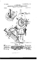
In the accompanying drawings, Figure 1 is a perspective view illustrative of the inven- Fig. 2' is a sectional elevation showing the embroidering attach-3 ment operatively mounted on a sewing-machine. Fig. 3 is a detail view of the pawland-ratchet device for rotating the guides. Fig. 4 is a detail sectional view of the spoolsupporting and guide-rotating devices. Fig.
5 is a detail plan view showing the operative Arranged adjacent to and in front of the relation of the former to the presser-foot and Serial No. 100,307. (Nomndeld 1 the needle-hole in the throat-plate. Fig. 6 is a detail view to illustrate the adjustable connection of the supporting-bracket with the arm of the machine, and Fig.7 illustrates a sample of one form of work which can be done by the invention.
Referring to the drawings, 12 denotes the forward end of the arm of a sewing-machine, which supports a bracket 13, having at its outer end a hub 14, in which is secured, as by the set-screw 15, a sleeve 16, around which moves a swinging arm 17, provided with a spring-pressed pawl 18, engaging a ratchet- ,wheel 19, rotating on said sleeve 16. The sleeve is notched or toothed at its lower end, so as to interlock with the similarly-constructed upper end of a rod 20', to the lower end of a which is rigidly attached the former 21, which ispreferably made fiat and slightly tapering or of decreasing thickness downward, so as to be slightly wedge-shaped in longitudinal or vertical section. The rod 20 is hollow'at its against the hub 14 the rod 20 will be rigidly fixed with relation to the fixed sleeve 16, and
thus the stationary former 21 will be securely held in working position.
The hub of the ratchet-wheel 19 has an interlocking or clutch connection at its lower end orside with the upper end of a sleeve 24, rotatively mounted on the rod 20, said sleeve having at its lower end a hub or collar'25, which carries the rotating strip or tape guides 26 and 27. The upper guide 26 rotates opposite the spool 28, mounted on the sleeve 24, and on which spool the tape or other embroidering strip of fabric is wound, and said guide 26 serves as a pull-off for the tape or strip, while the lower guide 27 rotates about the stationary former 21' and winds the tape or strip spirally around said former. This spiral disposition of the tape' or fabric strip on the former is due to the fact that it isconstantly being drawn from the former by the feedingde'vice of the machine as fast as it is tive engagement with the hub of the ratchet- Y wheel. 1
The main shaft 20 of the sewing-machine is provided with a gear-wheel 30, meshing with a second gear-wheel 31, journaled on a stud fixed to the head or frame of the machine and provided with a crank-pin 32, with which is engaged the upper end of a connecting-rod 33, the lower end of which engages a crank-pin 34 on the swinging pawlcarrying arm 17. The. crank- pins 32 and 34 are preferably made as ball-studs, so as to provide for proper freedom of movement of the parts, and the crank-pin 32 is also preferably connected with the gear wheel 31 through a bracket 35, attached to said gearwheel and in which the crank pin or stud may be adjustaby mounted, if desired, to vary the pawl-and-ratchet movement derived from said crank-pin; The crank-pin 34 may also be adjustably mounted in the pawl-oarrying arm 17 for this same purpose.
Backward movements of the ratchet-Wheel 19 are prevented by a spring-pressed detentpawl 36, mounted on an arm 37, attached to the bracket 13. A friction or tension plate 38, bearing against the upper flange of the spool 28, is preferably employed to restrain the said spool from turning too freely and to put a slight tension on the tape or other ornamental fabric strip as the latter is drawn from said spool.
For attaching one edge of a spirally-wound or serpentine tape or fabric strip 39 to the edge of a straight or curved strip or piece of fabric 40 the stationary former is preferably arranged approximately as shown in Fig. 5, with the right-hand edge of the former slightly to the right (in the line of the feed of the work) of the needle-hole 41 in the throatplate and mainlyin front of the presser-foot 44, so that the right-hand edges of the folds of the serpentine fabric strip will slightly overlap (in the line of the feed) the said needle-hole and also slightly overlap the edge of the straight or curved fabric or strip to which the serpentine strip is to be attached, a suitable guide for the said straight or curved fabric or strip being of course provided. By virtue, however, of the adjustable connection of the bracket 13 with the arm or head of the machine afforded by the slot 42 in a part of said bracket and through which slot the attaching screw or screws 43 pass the spirallywound or serpentine strip may be delivered to the needle in various ways, so that the line of stitches may run through the middle or other parts than the right-hand edge of the ornamentally-disposed strip, to which may be centrally stitched a cord or a narrow tape or braid to produce different kinds of ornamental trimmings; also, by providing formers of different widths and by varying the speed of rotation of the strip-guides agreat variety of embroidering or ornamental work may be performed throughv the instrumentality of the invention.
In the operation of the invention and after the ornamental strip has been led to the neodle and engaged with the machine feeding device the intermittingly-rotating guides 26 and 27 draw the tape or fabric strip from the spool and wind it spirally around the stationary former 21, from which it is drawn by the said feeding device as fast as it is being wound on said former, the lower edge of the former being of course slightly above the throatplate of the machine to enable the folds of the fabric strip to be readily discharged from the said former as the sewing operation progresses.
The invention is adapted for forming ornamental edgings and trimmings for curtains, dresses, and various articles and garments, as will be understood, and the details of the invention may be varied widely without departing from the essence thereof.
Having thus described my invention, I claim and desire to secure by Letters Patent- 1. A sewing-machine attachment comprisin g a supporting-bracket on which a spool for containing a wound-up ornamenting fabric strip may be rotatively mounted, combined with a stationary former supported above the work-plate of the machine and in front of the needle thereof, in the line of the feed of the work, by said bracket, rotating pull-ofi and winding guides for drawing the fabric strip from said spool and winding it about said a stationary former supported above the work-plate of the machine and in front of the needle thereof by said bracket,rotating guides for drawing the fabric strip from said spool and winding it about said former, and means for operating said rotating guides.
3. A sewing-machine attachment comprising a supporting-bracket on Which a spool for containing a wound-up ornamenting fabric strip may be rotatively mounted, combined with a stationary former supported above the work-plate of the machine and in front of the needle thereof by said bracket, rotating guides for drawing the fabric strip from said spool and winding it about said former, and
means for operatingsaid rotating guides, one of said guides being arranged adjacent to the said spool, to serve asa pull-0E for the fabric strip, and the other of said guides being located adjacent to said former and serving to wind the ornamenting fabric strip around the said former.
4. The combination with the bracket 13 adapted to beattached to the head of a sewing-machine, of a stationary'former, 21 supported in front of the needle by said bracket, a spool for containing theembroidering-strip also supported by said bracket, the strip guides 26 and 27 said guide 26 being arranged adjacent to said spool and said guide 27 being arranged adjacent to said former, a ratchetwheel operatively connected with said-guides for the purpose ofrotating the same about said spool and former, and means for operating said ratchet-wheel.
5. The combination with the sewing-ma- I chine head 12, of a bracket attached to said head, the stationary former 21 supported in front of the needle by'said bracket, a spool for containing the embroidering-strip also supported by said bracket, the strip-guide 26 arranged adjacent to said spool, thestripguide 27 arrangedadjacent to said former, a
Priority Applications (1)
| Application Number | Priority Date | Filing Date | Title |
|---|---|---|---|
| US10080702A US740654A (en) | 1902-03-31 | 1902-03-31 | Embroidering attachment for sewing-machines. |
Applications Claiming Priority (1)
| Application Number | Priority Date | Filing Date | Title |
|---|---|---|---|
| US10080702A US740654A (en) | 1902-03-31 | 1902-03-31 | Embroidering attachment for sewing-machines. |
Publications (1)
| Publication Number | Publication Date |
|---|---|
| US740654A true US740654A (en) | 1903-10-06 |
Family
ID=2809154
Family Applications (1)
| Application Number | Title | Priority Date | Filing Date |
|---|---|---|---|
| US10080702A Expired - Lifetime US740654A (en) | 1902-03-31 | 1902-03-31 | Embroidering attachment for sewing-machines. |
Country Status (1)
| Country | Link |
|---|---|
| US (1) | US740654A (en) |
Cited By (3)
| Publication number | Priority date | Publication date | Assignee | Title |
|---|---|---|---|---|
| US4418875A (en) * | 1980-09-30 | 1983-12-06 | Roadrunner Electronic Products Limited | Threading tool |
| US20070137540A1 (en) * | 2003-11-19 | 2007-06-21 | Tokai Kogyo Mishin Kabushiki Kaisha | Sewing machine |
| US20110113998A1 (en) * | 2009-11-18 | 2011-05-19 | Tokai Kogyo Mishin Kabushiki Kaisha | Sewing machine |
-
1902
- 1902-03-31 US US10080702A patent/US740654A/en not_active Expired - Lifetime
Cited By (5)
| Publication number | Priority date | Publication date | Assignee | Title |
|---|---|---|---|---|
| US4418875A (en) * | 1980-09-30 | 1983-12-06 | Roadrunner Electronic Products Limited | Threading tool |
| US20070137540A1 (en) * | 2003-11-19 | 2007-06-21 | Tokai Kogyo Mishin Kabushiki Kaisha | Sewing machine |
| US7370592B2 (en) * | 2003-11-19 | 2008-05-13 | Tokai Kogyo Mishin Kabushiki Kaisha | Sewing machine |
| US20110113998A1 (en) * | 2009-11-18 | 2011-05-19 | Tokai Kogyo Mishin Kabushiki Kaisha | Sewing machine |
| US8312823B2 (en) * | 2009-11-18 | 2012-11-20 | Tokai Kogyo Mishin Kabushiki Kaisha | Sewing machine |
Similar Documents
| Publication | Publication Date | Title |
|---|---|---|
| US740654A (en) | Embroidering attachment for sewing-machines. | |
| US331026A (en) | Sewing-machine | |
| US1024316A (en) | Strip folding and guiding attachment for sewing-machines. | |
| US2636464A (en) | Rotary take-up for sewing machines | |
| US1351866A (en) | Sewing-machine | |
| US1166834A (en) | Take-up mechanism for sewing-machines. | |
| US773653A (en) | Embroidering-machine. | |
| US785168A (en) | Revolving-hook sewing-machine. | |
| US672467A (en) | Overseaming sewing-machine. | |
| US160512A (en) | Improvement in sewing-machines | |
| US1015967A (en) | Strip folding and guiding attachment for sewing-machines. | |
| US179709A (en) | Improvement in sewing-machines for embroidering | |
| US595090A (en) | abbes | |
| US251852A (en) | estayer | |
| US2314513A (en) | Rotary take-up for sewing machines | |
| US250645A (en) | Franklin h | |
| US582314A (en) | Machine | |
| US498216A (en) | Sewing-machine | |
| US593733A (en) | Machine | |
| US185811A (en) | Improvement in sewing-machines for embroidering | |
| US161895A (en) | Improvement in sewing-machines | |
| US1005831A (en) | Sewing-machine. | |
| US434155A (en) | leilich | |
| US1536041A (en) | Embroidering machine | |
| US293478A (en) | Machine for sewing loops to the surface of fabrics |