US7354182B2 - Lighting assembly and a wheel rim including a lighting assembly - Google Patents
Lighting assembly and a wheel rim including a lighting assembly Download PDFInfo
- Publication number
- US7354182B2 US7354182B2 US11/111,350 US11135005A US7354182B2 US 7354182 B2 US7354182 B2 US 7354182B2 US 11135005 A US11135005 A US 11135005A US 7354182 B2 US7354182 B2 US 7354182B2
- Authority
- US
- United States
- Prior art keywords
- assembly
- lighting assembly
- coupled
- selectively
- lighting
- Prior art date
- Legal status (The legal status is an assumption and is not a legal conclusion. Google has not performed a legal analysis and makes no representation as to the accuracy of the status listed.)
- Expired - Fee Related, expires
Links
Images


Classifications
-
- B—PERFORMING OPERATIONS; TRANSPORTING
- B60—VEHICLES IN GENERAL
- B60Q—ARRANGEMENT OF SIGNALLING OR LIGHTING DEVICES, THE MOUNTING OR SUPPORTING THEREOF OR CIRCUITS THEREFOR, FOR VEHICLES IN GENERAL
- B60Q1/00—Arrangement of optical signalling or lighting devices, the mounting or supporting thereof or circuits therefor
- B60Q1/26—Arrangement of optical signalling or lighting devices, the mounting or supporting thereof or circuits therefor the devices being primarily intended to indicate the vehicle, or parts thereof, or to give signals, to other traffic
- B60Q1/32—Arrangement of optical signalling or lighting devices, the mounting or supporting thereof or circuits therefor the devices being primarily intended to indicate the vehicle, or parts thereof, or to give signals, to other traffic for indicating vehicle sides, e.g. clearance lights
- B60Q1/326—Arrangement of optical signalling or lighting devices, the mounting or supporting thereof or circuits therefor the devices being primarily intended to indicate the vehicle, or parts thereof, or to give signals, to other traffic for indicating vehicle sides, e.g. clearance lights on or for wheels
-
- B—PERFORMING OPERATIONS; TRANSPORTING
- B60—VEHICLES IN GENERAL
- B60Q—ARRANGEMENT OF SIGNALLING OR LIGHTING DEVICES, THE MOUNTING OR SUPPORTING THEREOF OR CIRCUITS THEREFOR, FOR VEHICLES IN GENERAL
- B60Q2900/00—Features of lamps not covered by other groups in B60Q
- B60Q2900/30—Lamps commanded by wireless transmissions
Definitions
- the present invention generally relates to a lighting assembly and to a wheel rim incorporating a lighting assembly and more particularly, to a lighting assembly which is adapted to be either selectively and operatively deployed within a wheel, or integrally and operatively placed within a portion of wheel or a wheel rim of a selectively movable assembly, such as and without limitation a vehicle, and which provides aesthetically pleasing illumination in a new and novel manner.
- a selectively movable apparatus or assembly such as and without limitation, a motorized vehicle.
- This desirability emanates, in part, from a desire to selectively illuminate at least a portion of the environment immediately surrounding or disposed along the sides of the selectively movable assembly in order to promote safety (e.g., by allowing operators of other selectively movable assemblies in close proximity to the illuminated assembly to effectively and accurately view or see the illuminated assembly and to allow those individuals in close proximity to the illuminated assembly (e.g., a parked vehicle) to have an illuminated environment).
- This desirability also emanates, in part, from a desire to enhance the overall aesthetic visual appearance of the selectively movable assembly and to allow the owner of the assembly to personalize the assembly and to make a “statement” to those viewing the assembly.
- the present invention overcomes these and other disadvantages of the prior illumination techniques and strategies.
- a lighting assembly includes a body portion which is selectively placed within a wheel rim bore; and a light generation assembly which is operatively contained within the body portion.
- an assembly for use in combination with a wheel rim of the type having a center bore of a certain shape includes a body having a shape which is substantially identical but slightly smaller than the certain shape; and a lighting assembly which is operatively housed within the body and which selectively generates light.
- a wheel rim is provided and includes a center bore; and a lighting assembly which is operatively contained within the center bore.
- FIG. 1 is a side schematic view of a lighting, assembly which is made in accordance with the teachings of the preferred, although non-limiting, embodiment of the invention
- FIG. 2 is a perspective view of one non-limiting example of a selectively movable assembly which incorporates the lighting assembly which is shown in FIG. 1 ;
- FIG. 3 is a front view of the adapter portion of the lighting assembly which is schematically shown in FIG. 1 ;
- FIG. 4 is a front view of the center bore mounting portion of the lighting assembly which is schematically shown in FIG. 1 ;
- FIG. 5 is a perspective unassembled view of the housing portion of the lighting assembly which is schematically shown in FIG. 1 ;
- FIG. 6 is an electrical schematic diagram of the control portion of the lighting assembly which is schematically shown in FIG. 1 ;
- FIG. 7 is a schematic diagram of the light, emission assembly which is schematically shown in FIG. 1 ;
- FIG. 8 is a front view of a lighting assembly which is made in accordance with the teachings of yet another alternate embodiment of the invention.
- FIGS. 1-7 there is shown a, lighting or selective illumination assembly 10 which is made in accordance with the teachings of the preferred embodiment of the invention and which overcomes some or all of the previously delineated drawbacks associated with prior lighting and illumination assemblies which are utilized on selectively movable apparatuses and assemblies, such as and without limitation a vehicle, such as vehicle 12 which is shown in FIG. 2 .
- the various lighting assemblies of the various inventions may be used in combination with or as an integral part of substantially any desired selectively movable assembly or a portion of substantially any desired selectively movable assembly (including but not limited to manually movable assemblies), and that the various inventions, which are more fully described herein, are not limited to a particular type or class of selectively movable assembly, but may be used with any such desired assembly. It should be further realized that the terms “lighting” and “illumination” are interchangeably used in this description and mean or refer to the selective emanation of light or illuminating energy.
- the lighting assembly 10 includes a housing 14 and a control portion 16 .
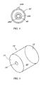
- the housing 14 is adapted to operatively house or contain the various light emitting and light emitting control portions of the assembly 10 (which are more fully described below) and, in one non-limiting embodiment of the invention, is generally cylindrical in shape (e.g., is generally shaped in the form of a conventional can), although other shapes may be utilized and it should be realized that the housing may have any desired shape.
- the housing 14 has a first substantially open end 15 and a second substantially closed end 17 which includes a relatively narrow aperture 19 .
- the interior of the housing 14 is generally hollow and defines a cavity 21 which communicates with the aperture 19 .
- the housing 14 may be manufactured from plastic, metal, or substantially any other desired commercially available material and may even include a plurality of diverse or composite materials, in a manner and for a purpose which is more fully described below, and has a diameter which is typically smaller than the diameter of the wheel rim bore in which it is to be operatively disposed (e.g., the housing 14 has a shape which is substantially identical to but slightly smaller than the shape of wheel rim bore in which it is disposed). It should be appreciated that the term “bore” refers to substantially any desired opening or aperture within a wheel rim or a wheel or any portion of a wheel assembly.
- the lighting assembly 10 further includes, in one non-limiting embodiment of the invention, a counterweight portion or member 30 which is coupled to at least a portion of the control portion 16 (e.g., the electric power generation portion), and, in one non-limiting embodiment, to the housing 14 , and a bearing assembly 32 which isolates the housing 14 from the wheel bore or wheel portion in which it is disposed. Further, the lighting assembly 10 includes an elongated threaded member 40 which traverses and operatively protrudes on either side of the aperture 19 , and is received by and traverses the bearing 32 .
- a first end 44 of the threaded member 40 is coupled to the control portion 16 (e.g., to the shaft of a generator which is included in the control portion 16 ), by use of a coupling member or some other member, while passing through the bearing assembly 32 , and a second and opposed end 46 of the threaded 40 member protrudes from the aperture 19 in a direction away from the control portion 16 .
- the end of the member 40 which passes through the bearing assembly 32 and is coupled to the control portion 16 need not necessarily be threaded, in other non-limiting embodiments of the invention and may even “drive” the generator or electrical power producing portion of the control portion 16 .
- the lighting assembly 10 further includes a wheel rim or bore or “central bore” adapter portion or assembly 50 including a first generally flat and spherical plate member 52 and a second and generally flat and spherical plate member 54 which, in one non-limiting embodiment of the invention, is substantially identical to the first member 52 .
- each of the members 52 , 54 have respective apertures 60 which are substantially and axially aligned and which respectively receive the threaded member 40 .
- the members 52 , 54 are initially placed upon the threaded member 40 in a mutually and linearly coextensive relationship or manner.
- the assembly 50 includes an abutment or frictional engagement member 70 (e.g., an O-ring) which is operatively and frictionally positioned between the two members 52 , 54 , which receives the threaded portion 40 (e.g., the threaded portion 40 traverses the member 70 ), and which is initially in a linearly coextensive relationship with the members 52 , 54 , although the abutment member 70 may have a larger diameter than either of the members 52 , 54 .
- an abutment or frictional engagement member 70 e.g., an O-ring
- the lighting assembly 10 includes a substantially convex reflector portion or member 80 which is operatively and frictionally fitted within the substantially open end 15 of the housing 14 , which substantially and operatively resides within the cavity 21 , and which is in a communication relationship with a light emission assembly 18 which is operatively included within the assembly 10 .
- the lighting assembly 10 further includes a chrome or decorative ring member 90 which is attached to the circumferential periphery of the substantially open end 15 of the housing 14 , thereby surrounding but exposing the portion 80 , and allowing the lighting assembly 10 to be even more aesthetically pleasing (e.g., the decorative ring member 90 is exposed and viewed by those in close proximity to the assembly upon which the lighting assembly 10 is disposed, such as vehicle 12 ).
- a chrome or decorative ring member 90 which is attached to the circumferential periphery of the substantially open end 15 of the housing 14 , thereby surrounding but exposing the portion 80 , and allowing the lighting assembly 10 to be even more aesthetically pleasing (e.g., the decorative ring member 90 is exposed and viewed by those in close proximity to the assembly upon which the lighting assembly 10 is disposed, such as vehicle 12 ).
- the lighting assembly 10 further includes a cam member 100 which is movably disposed upon the threaded member 40 since the member 100 includes a threaded aperture 102 having threads which are complementary to the threads included upon the threaded member 40 and which includes, in the most preferred, although non-limiting embodiment of the invention, a substantially triangular cross sectional area.
- the term “complementary” means that the threads which are disposed within the aperture 102 cooperate with the threads which are resident upon the threaded member 40 to allow the cam member 100 to selectively and axially move upon the threaded member 40 from a first position which is remote from the member 52 to a second position in which the member 100 engages the member 52 .
- the lighting assembly 10 further includes a nut or other member 204 which is movably disposed upon the threaded member 40 in the same manner in which the cam member 100 is movably disposed upon the threaded member 40 . In this manner, the nut 204 is used to selectively compress the cam member 100 against the member 52 and to allow the member 52 to be remote from or be in a disengaging relationship with the member 52 .
- the housing 14 includes a clear or substantially transparent lens portion 210 which substantially surrounds the light emission assembly 18 and, in yet further non-limiting embodiments of the invention, the member 52 includes projections or bullet portions, such as portion 220 of FIG. 4 , which allows the displaced member 52 to be fitted within bores of even greater diameters (e.g., the portions, such as portion 220 , selectively engage the interior surface of a wheel rim bore, such as interior surface 1 of one of the bores 3 ).
- a second cam member which is substantially similar to cam member 100 , may be movably disposed upon the threaded member 40 and adapted to selectively engage the member 54 , thereby forcing the member 54 in the direction of arrow 200 .
- Such movement of this second provided cam member is independent of the movement of the cam member 100 and the movement of the member 54 in the foregoing manner in combination with the aforedescribed movement of cam member 52 increases the likelihood that the lighting assembly 10 will remain fitted within a large diameter wheel rim bores, such as one of the bores 3 of rims 802 , 804 .
- both the members 52 , 54 will selectively engage the internal surface of the large diameter wheel bore, such as bore 3 , thereby increasing the “placement stability” of the lighting assembly 10 within these types of large diameter bores.
- the second cam member may also have projection or bullet portions, such as portion 220 .
- a retainer adapter member 240 is disposed upon the threaded member 40 and in an engagement relationship with the case or housing portion 14 while allowing member 40 to pass there through.
- This member 240 may be formed from plastic, rubber, or substantially any other desired material and is adapted to have a length or diameter 300 which is substantially longer than the length or diameter 302 of the member 52 , thereby allowing the lighting assembly 10 to be placed within relatively large diameter wheel rim bores (e.g., the member 240 frictionally fits and is secured within the respective interior surfaces of these relatively large wheel rim bores, such as interior surfaces 1 of bores 802 and 804 ).
- the lighting assembly 10 may be selectively and operatively placed within substantially any wheel bore having substantially any diameter and that such placement may be effectuated by the utilization of a member 240 having a diameter or length 300 which is substantially similar to (e.g., is slightly larger than) the diameter or length of the bore to which it is to be placed (e.g., by increasing the diameter or length of the member 240 , one may place the assembly 10 in even larger diameter wheel rim bores than that which may contain the assembly 10 without the member 240 ).
- the member 240 may obviate the need for assembly 50 .
- the control assembly or portion 16 includes an electrical power source 400 which may comprise a battery (e.g., a lithium-ion type battery), a generator, and/or the conventional and normally supplied battery of the vehicle 12 or other selectively movable assembly that the lighting assembly 10 is operatively disposed within and/or upon (e.g., in self-powered or “non-manual” applications).
- a battery e.g., a lithium-ion type battery
- a generator e.g., a lithium-ion type battery
- control assembly or portion 16 includes, in one non-limiting embodiment of the invention, a radio frequency, ultrasonic, infrared or other type of transceiver 404 , including an antenna 406 , and a microprocessor or other type of controller assembly 410 which is operable under stored program control and which includes the software, firmware, or a combination of software and firmware and/or other logic which is necessary to define the function and operation of the control portion 16 and of the entire lighting assembly 10 .
- the microprocessor or controller assembly 410 is physically and operatively coupled to the electrical power source 400 by the bus 420 and to the transceiver portion 404 by the bus 422 and may include both a central processor, such as by way of example and without limitation a Pentium® type processor and memory for storing the central control logic.
- the microprocessor or controller assembly 410 is further physically and operatively coupled to the light emission assembly 18 by the bus 430 .
- the control portion 16 includes a sound generator 442 which is physically and operatively coupled to the microprocessor or controller assembly 410 by the bus 446 and to the electrical power source by the bus 444 .
- the light emission assembly 18 includes several selectively and electrically energizable lighting elements 500 , 502 , 504 which, in one non-limiting embodiment of the invention, each comprise light emitting diodes of substantially any desired color, size, shape, and intensity. A desired number of such elements may be utilized within the light emission assembly 18 .
- each of the provided elements such as elements 500 , 502 , and 504 , are mounted upon a convex reflector member 510 which is in close proximity to and in communication relationship with the convex mirror 80 and the lens 210 , and which is fixedly positional within the cavity 21 of the housing 14 (e.g., by the use of glue or some other conventional type of fastener elements of assembly).
- a user such as user 600 utilizes a key fob or transmitter 610 which is adapted to selectively generate signals, such as signal 700 , which are received by the antenna 406 , communicated from the antenna 406 to the transceiver 404 , demodulated by the transceiver 404 , and then communicated to the microprocessor or controller assembly 410 where, they respectively cause the microprocessor or controller 410 to perform some action depending upon the nature or type of the signal and the stored program (e.g., the then current central state that the contained control “logic” resides within).
- the transmitter 610 may be of “the battery powered type” and be substantially similar to a commercially available remote keyless entry or automobile alarm transmitter and may even be voice activated.
- a first signal such as signal 700
- the microprocessor or controller assembly 420 may be effective to cause the microprocessor or controller assembly 420 to source electricity from the power source 400 to the light emission assembly 18 , thereby selectively and electrically energizing each of the members or elements, such as 500 , 502 , 504 , and causing light signals 800 to be generated from at least one of the wheel rims 802 , 804 of vehicle 12 .
- a second such signal may cause microprocessor or controller assembly 410 to source electrical energy from the source 400 to the sound generator 442 , thereby allowing sound to selectively emanate from the vehicle 12 or other selectively movable assembly.
- the sound may be “preprogrammed” or stored within the microprocessor or controller assembly 410 and/or selectively programmed or placed into the assembly 410 by a user of the assembly 10 .
- a third such signal may be effective to cause the microprocessor or controller assembly 410 to interrupt the transmission of electrical energy to the light emission assembly 18 and/or to the sound generator 442 , thereby selectively “deactivating” the lighting assembly 10 .
- the light emission assembly 18 upon receipt of electrical energy, the light emission assembly 18 is selectively energized and generates light energy which is communicated to the portions 510 and 80 from the energized members, such as members 500 , 502 , 504 , and then reflected from portions 510 and 80 before emanating through the ring 90 into the environment in which the selectively movable assembly, such as vehicle 12 is operatively deployed.
- the counterweight 30 in the previously described non-limiting embodiment, substantially prevents housing 14 from rotating or turning with the wheel rims, such as wheel rims 802 , 804 .
- the shaft 40 does turn the electric power generation portion (e.g., a generator), thereby allowing the generator to generate electricity.
- the assembly 810 includes a substantially transparent central portion 812 which is adapted to be selectively and movably placed upon the end 15 of the housing 14 (e.g., the central portion 812 is loosely and frictionally placed upon the end 15 ) which substantially overlaying the mirror 80 , and including, substantially identical propeller projections 814 , 816 which move or rotate in response to the movement of the wheel rim that they are disposed upon.
- a monogram or written portion 820 may be placed upon the central portion 812 to increase the overall aesthetic appearance of the lighting assembly 10 .
- the member of propeller portions 814 , 816 may vary and that the size and shape of these portions, such as portions 814 , 816 may vary as desired.
- the counterweight portion 30 , the control portion 16 , and the light emission portion 18 , and the portion 80 are removed from the housing 14 and the portion 810 is directly attached to the bearing 32 , thereby selectively rotating with the movement of the rim, such as rims 802 , 803 .
- illuminated tape, paint, and/or other decorative substances and/or elements may be selectively placed upon the portion 810 and/or to the portions, such as portions 814 , 816 .
- the control portion 16 may include a trickle charger which is operatively coupled to the battery/power source 400 and the assembly 18 and is effective to selectively maintain the energization of the assembly 18 .
- lighting assembly 10 may be integrally formed within the wheels, rims, such as wheel rims 802 , 804 and that assembly 10 is relatively easy to install, maintain, and replace, is of a substantially uncomplicated design and is very cost effective.
- the counterweight 30 may alternatively be coupled to the housing 14 or an additional counterweight may be coupled to the housing 14 .
- the bearing assembly 32 is removed and member 40 terminates in an “uncoupled manner” within cavity 10 .
- the counterweight 30 is only coupled to the generator shaft or electrical power source 400 (and not to member 40 ), thereby allowing the housing 14 to selectively rotate while maintaining the light emitting portion 18 in a stationary position.
- unique assemblies 10 may be respectively placed in unique wheel bores of a movable assembly (e.g., each such bore includes a unique assembly 10 ).
Landscapes
- Engineering & Computer Science (AREA)
- Mechanical Engineering (AREA)
- Lighting Device Outwards From Vehicle And Optical Signal (AREA)
- Arrangement Of Elements, Cooling, Sealing, Or The Like Of Lighting Devices (AREA)
Abstract
Description
Claims (17)
Priority Applications (4)
| Application Number | Priority Date | Filing Date | Title |
|---|---|---|---|
| US11/111,350 US7354182B2 (en) | 2004-06-16 | 2005-04-21 | Lighting assembly and a wheel rim including a lighting assembly |
| PCT/US2006/014289 WO2006115860A2 (en) | 2005-04-21 | 2006-04-17 | A lighting assembly and a wheel rim including a lighting assembly |
| EP06750352A EP1871643A2 (en) | 2005-04-21 | 2006-04-17 | A lighting assembly and a wheel rim including a lighting assembly |
| CA002607439A CA2607439A1 (en) | 2005-04-21 | 2006-04-17 | A lighting assembly and a wheel rim including a lighting assembly |
Applications Claiming Priority (2)
| Application Number | Priority Date | Filing Date | Title |
|---|---|---|---|
| US58033604P | 2004-06-16 | 2004-06-16 | |
| US11/111,350 US7354182B2 (en) | 2004-06-16 | 2005-04-21 | Lighting assembly and a wheel rim including a lighting assembly |
Publications (2)
| Publication Number | Publication Date |
|---|---|
| US20060152938A1 US20060152938A1 (en) | 2006-07-13 |
| US7354182B2 true US7354182B2 (en) | 2008-04-08 |
Family
ID=37215226
Family Applications (1)
| Application Number | Title | Priority Date | Filing Date |
|---|---|---|---|
| US11/111,350 Expired - Fee Related US7354182B2 (en) | 2004-06-16 | 2005-04-21 | Lighting assembly and a wheel rim including a lighting assembly |
Country Status (4)
| Country | Link |
|---|---|
| US (1) | US7354182B2 (en) |
| EP (1) | EP1871643A2 (en) |
| CA (1) | CA2607439A1 (en) |
| WO (1) | WO2006115860A2 (en) |
Cited By (28)
| Publication number | Priority date | Publication date | Assignee | Title |
|---|---|---|---|---|
| US20070274085A1 (en) * | 2006-05-25 | 2007-11-29 | Terrance Hampton | Illuminated display system for vehicle wheels |
| US20130293105A1 (en) * | 2010-01-22 | 2013-11-07 | Gregory A. Day | Vehicle Exterior Lighting System |
| US9428007B1 (en) | 2015-11-16 | 2016-08-30 | Mark L. Becker | Illuminated vehicle wheel |
| US20170246985A1 (en) * | 2016-02-26 | 2017-08-31 | Ford Global Technologies, Llc | Vehicle illumination system |
| US9802534B1 (en) | 2016-10-21 | 2017-10-31 | Ford Global Technologies, Llc | Illuminated vehicle compartment |
| US20170332458A1 (en) * | 2016-05-11 | 2017-11-16 | Ford Global Technologies, Llc | Vehicle lighting assembly |
| US9840193B1 (en) | 2016-07-15 | 2017-12-12 | Ford Global Technologies, Llc | Vehicle lighting assembly |
| US9840191B1 (en) | 2016-07-12 | 2017-12-12 | Ford Global Technologies, Llc | Vehicle lamp assembly |
| US9849829B1 (en) | 2017-03-02 | 2017-12-26 | Ford Global Technologies, Llc | Vehicle light system |
| US9863171B1 (en) | 2016-09-28 | 2018-01-09 | Ford Global Technologies, Llc | Vehicle compartment |
| US9868318B2 (en) | 2015-11-16 | 2018-01-16 | Mark L. Becker | Illuminated vehicle wheel |
| US20180022149A1 (en) * | 2015-03-27 | 2018-01-25 | Bosswell Korea Inc. | Light emitting device for automobile wheel |
| US9987974B2 (en) | 2016-06-24 | 2018-06-05 | Ford Global Technologies, Llc | Lighting system having pointer device |
| US10043396B2 (en) | 2016-09-13 | 2018-08-07 | Ford Global Technologies, Llc | Passenger pickup system and method using autonomous shuttle vehicle |
| US10046688B2 (en) | 2016-10-06 | 2018-08-14 | Ford Global Technologies, Llc | Vehicle containing sales bins |
| US10053006B1 (en) | 2017-01-31 | 2018-08-21 | Ford Global Technologies, Llc | Illuminated assembly |
| US10065555B2 (en) | 2016-09-08 | 2018-09-04 | Ford Global Technologies, Llc | Directional approach lighting |
| US10086751B2 (en) | 2016-06-24 | 2018-10-02 | Ford Global Technologies, Llc | Vehicle lighting system having a spotlight |
| US10106074B2 (en) | 2016-12-07 | 2018-10-23 | Ford Global Technologies, Llc | Vehicle lamp system |
| US10118538B2 (en) | 2016-12-07 | 2018-11-06 | Ford Global Technologies, Llc | Illuminated rack |
| US10131237B2 (en) | 2016-06-22 | 2018-11-20 | Ford Global Technologies, Llc | Illuminated vehicle charging system |
| US10137829B2 (en) | 2016-10-06 | 2018-11-27 | Ford Global Technologies, Llc | Smart drop off lighting system |
| US10173582B2 (en) | 2017-01-26 | 2019-01-08 | Ford Global Technologies, Llc | Light system |
| US10205338B2 (en) | 2016-06-13 | 2019-02-12 | Ford Global Technologies, Llc | Illuminated vehicle charging assembly |
| US10483678B2 (en) | 2017-03-29 | 2019-11-19 | Ford Global Technologies, Llc | Vehicle electrical connector |
| US10720551B1 (en) | 2019-01-03 | 2020-07-21 | Ford Global Technologies, Llc | Vehicle lamps |
| US10730343B2 (en) | 2016-12-01 | 2020-08-04 | John P. MACHUCA | Vehicle rim plasma display assembly, apparatus and insert |
| US20240414828A1 (en) * | 2023-06-07 | 2024-12-12 | GM Global Technology Operations LLC | Systems and methods for controlling illumination of center caps in vehicle wheels |
Families Citing this family (2)
| Publication number | Priority date | Publication date | Assignee | Title |
|---|---|---|---|---|
| DE102006049788A1 (en) * | 2006-10-21 | 2008-01-17 | Audi Ag | Cover for a wheel hub or a wheel rim |
| US20130208491A1 (en) * | 2011-11-16 | 2013-08-15 | Charles E. Franklin | Stem light |
Citations (54)
| Publication number | Priority date | Publication date | Assignee | Title |
|---|---|---|---|---|
| US1539394A (en) | 1923-10-24 | 1925-05-26 | William F Gaffney | Illuminated hub cap |
| US1643593A (en) | 1926-10-09 | 1927-09-27 | John F Styer | Side light for automobiles |
| US2083514A (en) | 1935-06-26 | 1937-06-08 | Auto Hublight Company | Wheel hub light |
| US2526548A (en) | 1947-02-08 | 1950-10-17 | Franklin Joseph | Illuminated hubcap |
| US3016079A (en) | 1960-01-08 | 1962-01-09 | Eli J Weller | Traction device |
| US3099401A (en) | 1961-01-30 | 1963-07-30 | Joseph P Bell | Illumination means for automotive wheels |
| US3113727A (en) | 1961-06-27 | 1963-12-10 | Bradway Joseph | Illuminating apparatus for vehicle hub caps |
| US3140111A (en) | 1960-12-16 | 1964-07-07 | Frank C Dabroski | Illuminated rotatable resilient bumper |
| US3389937A (en) | 1966-08-08 | 1968-06-25 | Brumfield John Henry | Wheel cover and retaining means therefor |
| US4088882A (en) | 1975-08-12 | 1978-05-09 | Lewis Donald J | Fluorescent bike lamp |
| US4371916A (en) | 1978-10-30 | 1983-02-01 | Iao Industrie Riunite S.P.A. | Motor-vehicle lamp with base area illumination |
| US4381537A (en) | 1982-01-04 | 1983-04-26 | Hinrichs David K | Illusionary wheel cover structure |
| US4693389A (en) | 1986-01-31 | 1987-09-15 | The Babcock & Wilcox Company | Reactor internals core barrel hole plug |
| JPS63125402A (en) | 1986-11-14 | 1988-05-28 | Makoto Mineshima | Tire wheel lighting device for automobile wheel |
| US4787014A (en) | 1987-07-28 | 1988-11-22 | Wodder Terry G | Spoke mounted bicycle light |
| US4796972A (en) | 1987-12-24 | 1989-01-10 | Thomas Charles A | Illuminated spoke mounted reflector for bicycles |
| US4800469A (en) | 1987-11-23 | 1989-01-24 | Leon Thomas B | Wheel mounted safety light |
| JPH01103502A (en) | 1987-10-16 | 1989-04-20 | Techno Japan Kk | Illuminating lamp embedded tire |
| US4881153A (en) | 1989-01-17 | 1989-11-14 | David Duane Scott | Vehicle wheel lighting system |
| US5276593A (en) | 1993-05-03 | 1994-01-04 | Von Lighthill | Bicycle light signal |
| US5278732A (en) | 1992-10-20 | 1994-01-11 | John Frankum | Bicycle wheel portable light and reflector |
| US5455485A (en) | 1993-02-04 | 1995-10-03 | Kutter; Michael | Bicycle lighting system |
| US5530630A (en) | 1995-05-02 | 1996-06-25 | Williams, Jr.; Harry L. | Apparatus for lighting a vehicle wheel |
| US5552972A (en) | 1994-11-28 | 1996-09-03 | Rezvani; Vahid | Self-powered lighted wheel |
| US5800035A (en) | 1996-10-29 | 1998-09-01 | Aichele; William E. | Wheel lighting apparatus |
| GB2338180A (en) | 1998-06-13 | 1999-12-15 | Jeffrey Anderson | Flexible baby's cot |
| US6030106A (en) * | 1998-05-22 | 2000-02-29 | Johnson; Johnnie Lee | Light display for a vehicular wheel |
| US6168301B1 (en) | 1998-04-17 | 2001-01-02 | Marvin R. Martinez | Wheel luminaire |
| US6322237B1 (en) | 2000-07-17 | 2001-11-27 | Dennis Ray Lee | Lighted wheel rim system |
| US20010050611A1 (en) | 2000-03-22 | 2001-12-13 | Nolex Ag | Tire pressure display device |
| US6382820B1 (en) | 2000-09-15 | 2002-05-07 | Hyon Chol Chung | Illuminating novelty device for a hubcap |
| US20020089858A1 (en) | 2001-01-09 | 2002-07-11 | Deutsch Daniel J. | Light for vehicle wheels |
| US20020131274A1 (en) | 2001-01-16 | 2002-09-19 | Pittello Anthony J. | Vehicle-wheel light assembly |
| US20020163792A1 (en) | 2001-05-03 | 2002-11-07 | Formoso Vincent J. | Illuminated tire valve cap |
| US20020172036A1 (en) * | 2001-05-18 | 2002-11-21 | Highly Chien | Automatic power generating device in combination with illumination lamps mounted to wheels |
| US20030031019A1 (en) | 2001-08-13 | 2003-02-13 | Irene Chen | Light-emitting structure for tires |
| US6601979B1 (en) | 1999-02-02 | 2003-08-05 | Ronald L. Byrd | Wheel illumination device |
| US6612726B1 (en) | 2002-02-08 | 2003-09-02 | Cary Gloodt | Illuminated automobile wheels |
| US20030169596A1 (en) | 2002-01-28 | 2003-09-11 | Allen Sharper | Vehicle wheel illumination system |
| US20030198059A1 (en) | 2002-04-18 | 2003-10-23 | Albert Castro | Vehicle wheel illumination device |
| US20030202356A1 (en) | 2002-04-30 | 2003-10-30 | Hung Pao-Chuang | Means for illuminating wheel |
| US6644839B2 (en) | 2002-03-08 | 2003-11-11 | Dennis R. Lee | Lighted wheel rim system |
| US20040125612A1 (en) | 2002-12-12 | 2004-07-01 | John Jackson | Lighting system and device for automobile wheels |
| US20040130905A1 (en) | 2001-09-04 | 2004-07-08 | Roger Olds | Vehicle illumination system |
| JP2004224188A (en) | 2003-01-23 | 2004-08-12 | Tsuneo Asaba | Tire wheel center cap |
| JP2004276888A (en) | 2003-03-13 | 2004-10-07 | Hidehito Shimooka | Light emitting device for wheel for two-wheeler |
| JP2004276887A (en) | 2003-03-13 | 2004-10-07 | Hidehito Shimooka | Lighting system for tire having luminous function |
| US20040257825A1 (en) | 2003-06-18 | 2004-12-23 | Nakim Choi | Light emitting device for use in vehicle wheel |
| US20040264207A1 (en) | 2003-06-24 | 2004-12-30 | Jones Bo T. | Wheel light device |
| US20050030755A1 (en) | 2003-08-08 | 2005-02-10 | Mark Thomas | Methods and apparatuses for illuminating wheel surfaces |
| US20050030756A1 (en) | 2003-08-08 | 2005-02-10 | Mark Thomas | Methods and apparatuses for providing strobe effects for wheel illumination systems and wheel lighting systems |
| US20050052069A1 (en) | 2003-09-08 | 2005-03-10 | Stuart Gilly | Wheel spinner assembly |
| US20050099820A1 (en) | 2003-11-12 | 2005-05-12 | Cooper William G. | Wheel illumination device |
| US7052170B2 (en) * | 2000-09-29 | 2006-05-30 | Striebel Roman F | Super bright LED utility and emergency light |
Family Cites Families (1)
| Publication number | Priority date | Publication date | Assignee | Title |
|---|---|---|---|---|
| US5267593A (en) * | 1992-11-09 | 1993-12-07 | Patterson Arlin V | Router spindle adapter apparatus |
-
2005
- 2005-04-21 US US11/111,350 patent/US7354182B2/en not_active Expired - Fee Related
-
2006
- 2006-04-17 EP EP06750352A patent/EP1871643A2/en not_active Withdrawn
- 2006-04-17 CA CA002607439A patent/CA2607439A1/en not_active Abandoned
- 2006-04-17 WO PCT/US2006/014289 patent/WO2006115860A2/en not_active Ceased
Patent Citations (54)
| Publication number | Priority date | Publication date | Assignee | Title |
|---|---|---|---|---|
| US1539394A (en) | 1923-10-24 | 1925-05-26 | William F Gaffney | Illuminated hub cap |
| US1643593A (en) | 1926-10-09 | 1927-09-27 | John F Styer | Side light for automobiles |
| US2083514A (en) | 1935-06-26 | 1937-06-08 | Auto Hublight Company | Wheel hub light |
| US2526548A (en) | 1947-02-08 | 1950-10-17 | Franklin Joseph | Illuminated hubcap |
| US3016079A (en) | 1960-01-08 | 1962-01-09 | Eli J Weller | Traction device |
| US3140111A (en) | 1960-12-16 | 1964-07-07 | Frank C Dabroski | Illuminated rotatable resilient bumper |
| US3099401A (en) | 1961-01-30 | 1963-07-30 | Joseph P Bell | Illumination means for automotive wheels |
| US3113727A (en) | 1961-06-27 | 1963-12-10 | Bradway Joseph | Illuminating apparatus for vehicle hub caps |
| US3389937A (en) | 1966-08-08 | 1968-06-25 | Brumfield John Henry | Wheel cover and retaining means therefor |
| US4088882A (en) | 1975-08-12 | 1978-05-09 | Lewis Donald J | Fluorescent bike lamp |
| US4371916A (en) | 1978-10-30 | 1983-02-01 | Iao Industrie Riunite S.P.A. | Motor-vehicle lamp with base area illumination |
| US4381537A (en) | 1982-01-04 | 1983-04-26 | Hinrichs David K | Illusionary wheel cover structure |
| US4693389A (en) | 1986-01-31 | 1987-09-15 | The Babcock & Wilcox Company | Reactor internals core barrel hole plug |
| JPS63125402A (en) | 1986-11-14 | 1988-05-28 | Makoto Mineshima | Tire wheel lighting device for automobile wheel |
| US4787014A (en) | 1987-07-28 | 1988-11-22 | Wodder Terry G | Spoke mounted bicycle light |
| JPH01103502A (en) | 1987-10-16 | 1989-04-20 | Techno Japan Kk | Illuminating lamp embedded tire |
| US4800469A (en) | 1987-11-23 | 1989-01-24 | Leon Thomas B | Wheel mounted safety light |
| US4796972A (en) | 1987-12-24 | 1989-01-10 | Thomas Charles A | Illuminated spoke mounted reflector for bicycles |
| US4881153A (en) | 1989-01-17 | 1989-11-14 | David Duane Scott | Vehicle wheel lighting system |
| US5278732A (en) | 1992-10-20 | 1994-01-11 | John Frankum | Bicycle wheel portable light and reflector |
| US5455485A (en) | 1993-02-04 | 1995-10-03 | Kutter; Michael | Bicycle lighting system |
| US5276593A (en) | 1993-05-03 | 1994-01-04 | Von Lighthill | Bicycle light signal |
| US5552972A (en) | 1994-11-28 | 1996-09-03 | Rezvani; Vahid | Self-powered lighted wheel |
| US5530630A (en) | 1995-05-02 | 1996-06-25 | Williams, Jr.; Harry L. | Apparatus for lighting a vehicle wheel |
| US5800035A (en) | 1996-10-29 | 1998-09-01 | Aichele; William E. | Wheel lighting apparatus |
| US6168301B1 (en) | 1998-04-17 | 2001-01-02 | Marvin R. Martinez | Wheel luminaire |
| US6030106A (en) * | 1998-05-22 | 2000-02-29 | Johnson; Johnnie Lee | Light display for a vehicular wheel |
| GB2338180A (en) | 1998-06-13 | 1999-12-15 | Jeffrey Anderson | Flexible baby's cot |
| US6601979B1 (en) | 1999-02-02 | 2003-08-05 | Ronald L. Byrd | Wheel illumination device |
| US20010050611A1 (en) | 2000-03-22 | 2001-12-13 | Nolex Ag | Tire pressure display device |
| US6322237B1 (en) | 2000-07-17 | 2001-11-27 | Dennis Ray Lee | Lighted wheel rim system |
| US6382820B1 (en) | 2000-09-15 | 2002-05-07 | Hyon Chol Chung | Illuminating novelty device for a hubcap |
| US7052170B2 (en) * | 2000-09-29 | 2006-05-30 | Striebel Roman F | Super bright LED utility and emergency light |
| US20020089858A1 (en) | 2001-01-09 | 2002-07-11 | Deutsch Daniel J. | Light for vehicle wheels |
| US20020131274A1 (en) | 2001-01-16 | 2002-09-19 | Pittello Anthony J. | Vehicle-wheel light assembly |
| US20020163792A1 (en) | 2001-05-03 | 2002-11-07 | Formoso Vincent J. | Illuminated tire valve cap |
| US20020172036A1 (en) * | 2001-05-18 | 2002-11-21 | Highly Chien | Automatic power generating device in combination with illumination lamps mounted to wheels |
| US20030031019A1 (en) | 2001-08-13 | 2003-02-13 | Irene Chen | Light-emitting structure for tires |
| US20040130905A1 (en) | 2001-09-04 | 2004-07-08 | Roger Olds | Vehicle illumination system |
| US20030169596A1 (en) | 2002-01-28 | 2003-09-11 | Allen Sharper | Vehicle wheel illumination system |
| US6612726B1 (en) | 2002-02-08 | 2003-09-02 | Cary Gloodt | Illuminated automobile wheels |
| US6644839B2 (en) | 2002-03-08 | 2003-11-11 | Dennis R. Lee | Lighted wheel rim system |
| US20030198059A1 (en) | 2002-04-18 | 2003-10-23 | Albert Castro | Vehicle wheel illumination device |
| US20030202356A1 (en) | 2002-04-30 | 2003-10-30 | Hung Pao-Chuang | Means for illuminating wheel |
| US20040125612A1 (en) | 2002-12-12 | 2004-07-01 | John Jackson | Lighting system and device for automobile wheels |
| JP2004224188A (en) | 2003-01-23 | 2004-08-12 | Tsuneo Asaba | Tire wheel center cap |
| JP2004276888A (en) | 2003-03-13 | 2004-10-07 | Hidehito Shimooka | Light emitting device for wheel for two-wheeler |
| JP2004276887A (en) | 2003-03-13 | 2004-10-07 | Hidehito Shimooka | Lighting system for tire having luminous function |
| US20040257825A1 (en) | 2003-06-18 | 2004-12-23 | Nakim Choi | Light emitting device for use in vehicle wheel |
| US20040264207A1 (en) | 2003-06-24 | 2004-12-30 | Jones Bo T. | Wheel light device |
| US20050030755A1 (en) | 2003-08-08 | 2005-02-10 | Mark Thomas | Methods and apparatuses for illuminating wheel surfaces |
| US20050030756A1 (en) | 2003-08-08 | 2005-02-10 | Mark Thomas | Methods and apparatuses for providing strobe effects for wheel illumination systems and wheel lighting systems |
| US20050052069A1 (en) | 2003-09-08 | 2005-03-10 | Stuart Gilly | Wheel spinner assembly |
| US20050099820A1 (en) | 2003-11-12 | 2005-05-12 | Cooper William G. | Wheel illumination device |
Non-Patent Citations (1)
| Title |
|---|
| Zinik Luxury Wheels, website printout, May 17, 2005. |
Cited By (38)
| Publication number | Priority date | Publication date | Assignee | Title |
|---|---|---|---|---|
| US20070274085A1 (en) * | 2006-05-25 | 2007-11-29 | Terrance Hampton | Illuminated display system for vehicle wheels |
| US20130293105A1 (en) * | 2010-01-22 | 2013-11-07 | Gregory A. Day | Vehicle Exterior Lighting System |
| US9210771B2 (en) * | 2010-01-22 | 2015-12-08 | Gregory A. Day | Vehicle exterior lighting system |
| US10442242B2 (en) * | 2015-03-27 | 2019-10-15 | Bosswell Korea Inc. | Light emitting device for automobile wheel |
| US20180022149A1 (en) * | 2015-03-27 | 2018-01-25 | Bosswell Korea Inc. | Light emitting device for automobile wheel |
| US9428007B1 (en) | 2015-11-16 | 2016-08-30 | Mark L. Becker | Illuminated vehicle wheel |
| US9868318B2 (en) | 2015-11-16 | 2018-01-16 | Mark L. Becker | Illuminated vehicle wheel |
| CN107128238A (en) * | 2016-02-26 | 2017-09-05 | 福特环球技术公司 | Vehicular illumination system |
| US9751458B1 (en) * | 2016-02-26 | 2017-09-05 | Ford Global Technologies, Llc | Vehicle illumination system |
| US20170246985A1 (en) * | 2016-02-26 | 2017-08-31 | Ford Global Technologies, Llc | Vehicle illumination system |
| US20170332458A1 (en) * | 2016-05-11 | 2017-11-16 | Ford Global Technologies, Llc | Vehicle lighting assembly |
| CN107448857A (en) * | 2016-05-11 | 2017-12-08 | 福特环球技术公司 | Vehicle lighting assembly |
| CN107448857B (en) * | 2016-05-11 | 2021-08-06 | 福特环球技术公司 | Vehicle Lighting Components |
| US10420189B2 (en) * | 2016-05-11 | 2019-09-17 | Ford Global Technologies, Llc | Vehicle lighting assembly |
| US10205338B2 (en) | 2016-06-13 | 2019-02-12 | Ford Global Technologies, Llc | Illuminated vehicle charging assembly |
| US10131237B2 (en) | 2016-06-22 | 2018-11-20 | Ford Global Technologies, Llc | Illuminated vehicle charging system |
| US10086751B2 (en) | 2016-06-24 | 2018-10-02 | Ford Global Technologies, Llc | Vehicle lighting system having a spotlight |
| US9987974B2 (en) | 2016-06-24 | 2018-06-05 | Ford Global Technologies, Llc | Lighting system having pointer device |
| US9840191B1 (en) | 2016-07-12 | 2017-12-12 | Ford Global Technologies, Llc | Vehicle lamp assembly |
| US9840193B1 (en) | 2016-07-15 | 2017-12-12 | Ford Global Technologies, Llc | Vehicle lighting assembly |
| US10065555B2 (en) | 2016-09-08 | 2018-09-04 | Ford Global Technologies, Llc | Directional approach lighting |
| US10043396B2 (en) | 2016-09-13 | 2018-08-07 | Ford Global Technologies, Llc | Passenger pickup system and method using autonomous shuttle vehicle |
| US9863171B1 (en) | 2016-09-28 | 2018-01-09 | Ford Global Technologies, Llc | Vehicle compartment |
| US10434938B2 (en) | 2016-10-06 | 2019-10-08 | Ford Global Technologies, Llc | Smart drop off lighting system |
| US10137829B2 (en) | 2016-10-06 | 2018-11-27 | Ford Global Technologies, Llc | Smart drop off lighting system |
| US10046688B2 (en) | 2016-10-06 | 2018-08-14 | Ford Global Technologies, Llc | Vehicle containing sales bins |
| US9802534B1 (en) | 2016-10-21 | 2017-10-31 | Ford Global Technologies, Llc | Illuminated vehicle compartment |
| US10730343B2 (en) | 2016-12-01 | 2020-08-04 | John P. MACHUCA | Vehicle rim plasma display assembly, apparatus and insert |
| US10118538B2 (en) | 2016-12-07 | 2018-11-06 | Ford Global Technologies, Llc | Illuminated rack |
| US10106074B2 (en) | 2016-12-07 | 2018-10-23 | Ford Global Technologies, Llc | Vehicle lamp system |
| US10562442B2 (en) | 2016-12-07 | 2020-02-18 | Ford Global Technologies, Llc | Illuminated rack |
| US10173582B2 (en) | 2017-01-26 | 2019-01-08 | Ford Global Technologies, Llc | Light system |
| US10053006B1 (en) | 2017-01-31 | 2018-08-21 | Ford Global Technologies, Llc | Illuminated assembly |
| US9849829B1 (en) | 2017-03-02 | 2017-12-26 | Ford Global Technologies, Llc | Vehicle light system |
| US10483678B2 (en) | 2017-03-29 | 2019-11-19 | Ford Global Technologies, Llc | Vehicle electrical connector |
| US10720551B1 (en) | 2019-01-03 | 2020-07-21 | Ford Global Technologies, Llc | Vehicle lamps |
| US20240414828A1 (en) * | 2023-06-07 | 2024-12-12 | GM Global Technology Operations LLC | Systems and methods for controlling illumination of center caps in vehicle wheels |
| US12349259B2 (en) * | 2023-06-07 | 2025-07-01 | GM Global Technology Operations LLC | Systems and methods for controlling illumination of center caps in vehicle wheels |
Also Published As
| Publication number | Publication date |
|---|---|
| WO2006115860A2 (en) | 2006-11-02 |
| EP1871643A2 (en) | 2008-01-02 |
| US20060152938A1 (en) | 2006-07-13 |
| CA2607439A1 (en) | 2006-11-02 |
| WO2006115860A3 (en) | 2007-11-01 |
Similar Documents
| Publication | Publication Date | Title |
|---|---|---|
| US7354182B2 (en) | Lighting assembly and a wheel rim including a lighting assembly | |
| US11904762B2 (en) | Vehicular exterior rearview mirror assembly with illumination module | |
| US7611267B2 (en) | Wheel illumination device | |
| US6206553B1 (en) | Single pivot mirror with security light | |
| US6644839B2 (en) | Lighted wheel rim system | |
| US5800035A (en) | Wheel lighting apparatus | |
| US20160023588A1 (en) | Removable Signaling Apparatus, System, and Method | |
| CN210014324U (en) | Vehicle sump lamp assembly | |
| US7588358B1 (en) | Single LED and lens assembly | |
| US6467939B2 (en) | Light for vehicle wheels | |
| US7111967B2 (en) | Hub light | |
| US20060209536A1 (en) | Lighting assembly and a wheel rim including a lighting assembly | |
| KR101136927B1 (en) | Illuminating emblem for automobile | |
| US11760126B2 (en) | Hubcap lighting system | |
| JP2005008139A (en) | Light emitting device for wheel of automobile | |
| US20140043839A1 (en) | Wheel mounted lighting assembly | |
| US6646613B1 (en) | Vehicle antenna light | |
| US20030058124A1 (en) | Decorative alert system | |
| KR20100006246U (en) | luminous wheel assembly for auto-mobile | |
| KR20210000126A (en) | Automobile Tire Wheel Lights | |
| JP3568913B2 (en) | Automatic wheel generator and its lamp device | |
| CN215174764U (en) | Light-emitting structure for balancing car light arrangement | |
| JP2000215353A (en) | Device for confirming bicycle position | |
| JP2001039369A (en) | Bicycle lighting system | |
| JP3142339U (en) | Vehicle lighting |
Legal Events
| Date | Code | Title | Description |
|---|---|---|---|
| FEPP | Fee payment procedure |
Free format text: PETITION RELATED TO MAINTENANCE FEES DISMISSED (ORIGINAL EVENT CODE: PMFS); ENTITY STATUS OF PATENT OWNER: MICROENTITY |
|
| REMI | Maintenance fee reminder mailed | ||
| FEPP | Fee payment procedure |
Free format text: PETITION RELATED TO MAINTENANCE FEES FILED (ORIGINAL EVENT CODE: PMFP); ENTITY STATUS OF PATENT OWNER: MICROENTITY |
|
| FEPP | Fee payment procedure |
Free format text: PETITION RELATED TO MAINTENANCE FEES DISMISSED (ORIGINAL EVENT CODE: PMFS); ENTITY STATUS OF PATENT OWNER: MICROENTITY |
|
| FEPP | Fee payment procedure |
Free format text: PETITION RELATED TO MAINTENANCE FEES FILED (ORIGINAL EVENT CODE: PMFP); ENTITY STATUS OF PATENT OWNER: MICROENTITY |
|
| LAPS | Lapse for failure to pay maintenance fees | ||
| REIN | Reinstatement after maintenance fee payment confirmed | ||
| FP | Lapsed due to failure to pay maintenance fee |
Effective date: 20120408 |
|
| FEPP | Fee payment procedure |
Free format text: PETITION RELATED TO MAINTENANCE FEES GRANTED (ORIGINAL EVENT CODE: PMFG); ENTITY STATUS OF PATENT OWNER: MICROENTITY |
|
| FPAY | Fee payment |
Year of fee payment: 4 |
|
| SULP | Surcharge for late payment | ||
| PRDP | Patent reinstated due to the acceptance of a late maintenance fee |
Effective date: 20130116 |
|
| STCF | Information on status: patent grant |
Free format text: PATENTED CASE |
|
| FEPP | Fee payment procedure |
Free format text: PATENT HOLDER CLAIMS MICRO ENTITY STATUS, ENTITY STATUS SET TO MICRO (ORIGINAL EVENT CODE: STOM); ENTITY STATUS OF PATENT OWNER: MICROENTITY |
|
| FPAY | Fee payment |
Year of fee payment: 8 |
|
| FEPP | Fee payment procedure |
Free format text: MAINTENANCE FEE REMINDER MAILED (ORIGINAL EVENT CODE: REM.); ENTITY STATUS OF PATENT OWNER: MICROENTITY |
|
| LAPS | Lapse for failure to pay maintenance fees |
Free format text: PATENT EXPIRED FOR FAILURE TO PAY MAINTENANCE FEES (ORIGINAL EVENT CODE: EXP.); ENTITY STATUS OF PATENT OWNER: MICROENTITY |
|
| STCH | Information on status: patent discontinuation |
Free format text: PATENT EXPIRED DUE TO NONPAYMENT OF MAINTENANCE FEES UNDER 37 CFR 1.362 |
|
| STCH | Information on status: patent discontinuation |
Free format text: PATENT EXPIRED DUE TO NONPAYMENT OF MAINTENANCE FEES UNDER 37 CFR 1.362 |