US735131A - Gas-operated firearm. - Google Patents
Gas-operated firearm. Download PDFInfo
- Publication number
- US735131A US735131A US66736198A US1898667361A US735131A US 735131 A US735131 A US 735131A US 66736198 A US66736198 A US 66736198A US 1898667361 A US1898667361 A US 1898667361A US 735131 A US735131 A US 735131A
- Authority
- US
- United States
- Prior art keywords
- slide
- breech
- bolt
- cam
- movement
- Prior art date
- Legal status (The legal status is an assumption and is not a legal conclusion. Google has not performed a legal analysis and makes no representation as to the accuracy of the status listed.)
- Expired - Lifetime
Links
- 230000009471 action Effects 0.000 description 57
- 239000007789 gas Substances 0.000 description 35
- 238000010304 firing Methods 0.000 description 17
- 238000004880 explosion Methods 0.000 description 9
- 230000000994 depressogenic effect Effects 0.000 description 6
- 230000007246 mechanism Effects 0.000 description 6
- 238000010276 construction Methods 0.000 description 3
- 230000000881 depressing effect Effects 0.000 description 3
- 210000003414 extremity Anatomy 0.000 description 3
- 230000014509 gene expression Effects 0.000 description 3
- 210000003813 thumb Anatomy 0.000 description 3
- 101150000595 CLMP gene Proteins 0.000 description 2
- 101100382322 Drosophila melanogaster Acam gene Proteins 0.000 description 2
- 239000000463 material Substances 0.000 description 2
- 231100000241 scar Toxicity 0.000 description 2
- NIOPZPCMRQGZCE-WEVVVXLNSA-N 2,4-dinitro-6-(octan-2-yl)phenyl (E)-but-2-enoate Chemical compound CCCCCCC(C)C1=CC([N+]([O-])=O)=CC([N+]([O-])=O)=C1OC(=O)\C=C\C NIOPZPCMRQGZCE-WEVVVXLNSA-N 0.000 description 1
- USXDFAGDIOXNML-UHFFFAOYSA-N Fulminate Chemical compound [O-][N+]#[C-] USXDFAGDIOXNML-UHFFFAOYSA-N 0.000 description 1
- JUJWROOIHBZHMG-UHFFFAOYSA-N Pyridine Chemical compound C1=CC=NC=C1 JUJWROOIHBZHMG-UHFFFAOYSA-N 0.000 description 1
- 238000004140 cleaning Methods 0.000 description 1
- 230000003028 elevating effect Effects 0.000 description 1
- 239000000945 filler Substances 0.000 description 1
- 210000003811 finger Anatomy 0.000 description 1
- 238000003780 insertion Methods 0.000 description 1
- 230000037431 insertion Effects 0.000 description 1
- 230000004048 modification Effects 0.000 description 1
- 238000012986 modification Methods 0.000 description 1
- 230000000717 retained effect Effects 0.000 description 1
- 238000005096 rolling process Methods 0.000 description 1
Images


Classifications
-
- F—MECHANICAL ENGINEERING; LIGHTING; HEATING; WEAPONS; BLASTING
- F41—WEAPONS
- F41A—FUNCTIONAL FEATURES OR DETAILS COMMON TO BOTH SMALLARMS AND ORDNANCE, e.g. CANNONS; MOUNTINGS FOR SMALLARMS OR ORDNANCE
- F41A19/00—Firing or trigger mechanisms; Cocking mechanisms
- F41A19/06—Mechanical firing mechanisms, e.g. counterrecoil firing, recoil actuated firing mechanisms
- F41A19/25—Mechanical firing mechanisms, e.g. counterrecoil firing, recoil actuated firing mechanisms having only slidably-mounted striker elements, i.e. percussion or firing pins
- F41A19/27—Mechanical firing mechanisms, e.g. counterrecoil firing, recoil actuated firing mechanisms having only slidably-mounted striker elements, i.e. percussion or firing pins the percussion or firing pin being movable relative to the breech-block
- F41A19/29—Mechanical firing mechanisms, e.g. counterrecoil firing, recoil actuated firing mechanisms having only slidably-mounted striker elements, i.e. percussion or firing pins the percussion or firing pin being movable relative to the breech-block propelled by a spring under tension
- F41A19/30—Mechanical firing mechanisms, e.g. counterrecoil firing, recoil actuated firing mechanisms having only slidably-mounted striker elements, i.e. percussion or firing pins the percussion or firing pin being movable relative to the breech-block propelled by a spring under tension in bolt-action guns
- F41A19/33—Arrangements for the selection of automatic or semi-automatic fire
Definitions
- a gun of the class specified in which upon the discharge of the gun the breech mechanism shall be operated to reload and redischarge the weapon, the action being either entirely automatic, to the end that the firing may continue uninterruptedly as long as the cartridge-supply is maintained, or semi-automatic, to the end that each discharge may be under the absolute control of the gunner.
- the object of the invention is to construct a gun of the character described in which the stress ofdischarge shall be distributed along the lines of greatest resistance and to so guide and control the moving parts of the mechanism. that they shall be positive and accurate in all their movements, whereby ruinous strains and fatal jamming of the parts are avoided,
- the invention consistsof a gun-barrel and a receiver provided with a breech-block which has'a reciprocatory movement from and toward the barrel to open and close the breech and a turning or rotary movement to lock it into engagement with orunlock it from the breech, combined with an automatic power device which upon each discharge of the weapon imparts said movements to the breech mechanism.
- said automatic power device is actuated by the force of the explosion of each cartridge and may be (and in the particular expression of the in ven tiveidea herein shown is) actuated by the gases of discharge.
- the invention consists of a suitable barrel and receiverand a ro- 6o tating and reciprocating breech-bolt, combind with a slide actuated by the gases of explosion, which slide is so connected to the breechbolt that upon each reciprocation of the slide the bolt is turned to unlock it, is thenwithdrawn from and returned to thebreech, and is finally turned to again lock it to the breech.
- the gas-actuated slide is operatively connected to the bolt by an interposed spring and a second slide, which latter slide has a part indirect engagement with the bolt to operate it.
- Means are also provided whereby the reciprocating and rotating movements are so timed with relation to each other that the one movement shall properly follow the other to secure the unlocking and opening or the closing and locking of the bolt, and, finally, the invention consists in certain general improvements in guns of the class specified, which improvements will be hereinafter described and then pointed out in the claims.
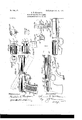
- Figure l is a side elevation of arepeatingpistol, illustrating the general appearance of the weapon.
- Fig.2 is an end elevation of Fig. 1'.
- Fig. 3 is a detail 5 illustrating the magazine-latch and its manner of engagement with the receiver.
- Fig. 4 is a detail 5 illustrating the magazine-latch and its manner of engagement with the receiver.
- Fig. 5 is a View of the operating-slide in plan and side elevation, and Fig. 5 is a broken detail showing the firing-pin on the slide H.
- I Fig. 6 is an elevation of the rear end of the same.
- Fig. 7 is a plan and end elevation of the cartridge-advancing slide.
- Fig. 8 is a view of the magazine cut-off in front and side elevation.
- Fig. 9 is a central longitudinal section of the weapon with the operating parts in their second or rear position.
- Fig. 10 is a side and top view of the sear.
- Fig. 11 is a side and top view of the carrier-lever.
- Fig. 12 is a side and top view of the main trigger.
- Fig. 13 is a transverse section of the arm on the lines a a
- Fig. 14 is a front elevation of the muzzle end of the weapon.
- Fig. 15 is a transverse section on the lines I) b
- Fig. 16 is a side elevation illustrating the general appearance and firing position of the weapon reduced to a vest-pocket size, showing in dotted lines the unlocked or open position of the action.
- Fig. 17 is a side elevation of the weapon with parts broken away and the barrel in longitudinal section.
- Fig. 18 is a bottom plan View of the breech-bolt and shell-extractors, and Fig. 18 is a rear elevation of Fig. 18.
- Fig. 18 is a rear elevation of Fig. 18.
- Fig. 19 is a side elevation of the breech-bolt.
- Fig. 20 is a front elevation of the inverted breech-bolt.
- Figs. 21 and 22 are detail illustrations of the companion locking-lugs on the side walls of the receiver.
- Fig. 23 is afront elevation of the cartridge-carrier.
- Fig. 24 is a side elevation of Fig. 22.
- Fig. 25 is a horizontal transverse section of the same on the line a: 00, Fig. 23, illustrating the grippingarms of the cartridge-holder and the camwedge by which they are separated to release the cartridge and the manner of locking engagement between the wedge and the grippingarms.
- Fig. 26 is a broken sectional view with the breech-bolt removed and the operating-slide in its rear position.
- Fig. 27 is a side elevation of the sear and auxiliary trigger, illustrating their construction and manner of engagement.
- Fig. 28 is a perspective view of the automatic latch which looks the
- the receiver may be of any desired shape to adapt it to the breech-bolt action, to which the invention is intended to be applied.
- it is designated by the reference-letter A and is illustrated as a hollow cylinder of sufficient length to entirely house the bolt in both its forward and rear positions. It is provided with an opening A to permit theinsertion and ejection of the carriage. It is also open at its rear end to admit the assembling and disassembling of the breech-action and is provided with a camtrack A in its lateral walls to govern the looking action of the bolt, Figs. 4, 9, 15, 17, and 25.
- the receiver is also provided with a forwardly-projecting arm A, Figs.
- the barrel B may be screwed into the receiver, as illustrated in Figs. 4 and 9, or it may be integrally formed with the receiver, as is illustrated in Fig. 17.
- the slide 0 forms a cylinder around the barrel and has a handle part which may be integrally formed therewith or may be hinged thereto and when so formed may have the incidental function of forming a sight for the arm.
- the forward end of this slide contains an opening 0 large enough to permit the passage of the projectile and is surrounded by the band 01., which is integrally formed with the arm A of the receiver. (See Fig. 14.)
- the spring F is located within the cylindrical slide 0 and resists its movement, and the slide is provided on its under side with cam-lugs O and C as illustrated in Figs. 4:, 9, 13, 17, which lugs govern its action and combination with relation to both the breech-bolt and cartridge-carrier, as hereinafter set forth.
- the handle D is hinged to the receiver by the pivot D and is of any suitable shape to conform to the grip of the hand and to meet the requirements of its relation to'the magazine and operatingparts.
- Located in the inside walls of the handle D are the guidegrooves M to control the reciprocating movements of the'cartridge-carrier, also the groove D to control the reciprocating movement of the cartridge-ad vancing slide R.
- the handle D is also chambered to admit the action and movement of the cartridge-magazine E.
- Thecartridge-magazine E is housed in the handle and may have any required form to adapt it to receive, retain, and release the cartridges and contains a coiled spring E and a follower E to exert a lifting tension on the cartridges.
- This magazine is preferably pivotally supported in the handle D to permit it to be sufficiently swung out at the side of the handle to allow the insertion of the cartridges either singly or from a cartridge clip or holder.
- a fixed position of the magazine when open is secured by the engagement of the lug E Fig. 2, with the handle.
- the magazine when closed is retained in position in the handle by any suitable form of catch, which I have illustrated in Figs.
- This latch E is provided with a checked knob conveniently located to be disengaged in opening the magazine by a lateral movement of the thumb across the rear side of the handle D.
- the barrel is ICC
- the slide H, Fig. 5 connects the dischargeactuated cylindrical slide 0 and the auxiliary actuating-spring G, Figs. 4 and 9, with the breech mechanism. It constitutes a reciprocating bar or bars preferably located beneath the barrel and receiver and has an arm H at its forward end projecting into the path of the auxiliary spring G and an arm H at its rearward end projecting into engagement with the bolt-action. It is provided with cam-lugsH and H", which latter enters into cam relation and cooperation with the camlug C The action of this slide H is governed by the cam guideways or tracks A and A Figs.
- the camway A is located in the side walls of the receiver proper and engages with the diamond-shaped lug H to govern the relation of the slide H to the bolt-action, as
- This actuating-slide H is provided near its rear end with a stud H to engage with and guide the cartridge-advancing slide R and is also provided on its under side with the before-mentioned cam lugs H to govern the action of the cartridge-carrier and the lugs H to engage with the sear, as will be hereinafter more fully set forth.
- the breech-bolt may have any desired form necessary to adapt it to any preferred form of breech-bolt-locking action to which the actuating device may be applied.
- the breechbolt forms a hollow cylinderhaving the usual cam-lockin g lugs at its forward end and is preferablyillustratedas a reciprocating and rotating breech-bolt. It .is denoted by the reference-letter I and has on its under side a cam guide-groove 1, Figs. 4, 9, 18, and 19,that has acam action sufiicient to bring the locking-lugs I of the breech-bolt into engagement with the locking-lugs A on the side walls of the receiver, Figs.
- the groove I in the breech-bolt has at its front end a straight part to permit a firing action after the looking action of the bolt is complete.
- the rear end Wall of the breech-bolt is shouldered and grooved to permit a locked engagement of the slide H with the breech-bolt, as illustrated in Fig. 9 and hereinafter more fully described.
- a spring latching device 1 Fig. 19 to form a latching engagement between the bolt and slide H during the reciprocating movements of the bolt and acting to time the rotating action of the bolt, the projecting portion of the catch 1 being engaged and operated by any suitable cam portion (not shown) on thereceiver at the instant when the bolt has completed its unlocking rotation, thereby forcing it into engagement with the slide and being free to escape by reason of its resiliency, when at the termination of its forward movement it escapes from the actuating-cam which holds it, thereby permitting the slide arm 11 to advance through the cam-slot I to rotate and lock the bolt. While I have shown this spring latching device I and sometimes employ it in addition to the latch engagement between the lip I and the part H. of the slide-arm, as hereinafter described, I may and frequently do entirely omit it, or I sometimes employ it alone to form the engagement between the bolt and slide and to determine or time the rolling action of the bolt.
- the shell-extractors are integrally attached to a divided collar which encircles the bolt, the respective opposite sides of which collar are centrally hinged together, as illustrated in Fig. 18.
- the preferred form, which is here illustrated, is that of an interlocking pivotless hinge, which form of hinge retains the extractors looked around the bolt under the influence of a spring 1 which permits a sufficient movement of their hooked ext-remi-- ties to allow them to engage with the carfridge, and when the actuating-spring I is removed from behind the extractors the form of binge permits them to be readily disassembled.
- the spring I is in the form of a spring-collar, which encircles the bolt behind the extractors and is provided with a projecting point of engagement 1*, which enters.
- the collar part of the extractors is located in a groove about-the neck of the bolt, and this extractor-collar bears against the groove in which it-is located only at a point in the center line of the collar and immediately in front of the central point at which the extractors are hinged together,
- the cartridge-carrier is composed of gripping-arms M, whichconform to the shape of the cartridge and maintain a yielding tension on the respective opposite sides of the cartridge, Figs. 4, 9, 15, 22, 23, and 24.
- the preferred form of the cartridge-carrier is that it shall be integrally formed from a single piece of material.
- the gripping-arms of the carrier as here illustrated, are provided on their respective opposite sides with projecting lugs M to engage'with the carrier-lever.
- the forward sides of these grippingarms are provided with shouldered wings M which project in toward the center of the carrier and enter into engagement with the camwedge M by which the arms of the carrier are actuated to grip and release the cartridge.
- This cam-wedge M as illustrated, is pivotally supported betweenthe gripping-arms of the carrier by means of the pivot M and has an arm or flange M projecting into the path of a lug, as H, on the slide H when the carrier is in its elevated position and the slide in its rear position, as shown in Fig. 9.
- the lug H first strikes the flange M and forces the wedge between the arms M and opens the carrier just as the cam-lug H on the slide H strikes the pin N on the carrier-lever to depress the carrier.
- the flange M strikes a portiom of the gun-frame and turns the wedge on its pivot and withdraws itto the position shown in Figs. 24 and 25.
- the carrier-lever N is formed from a single piece of material. Its preferred form is illustrated in Figs. 4, 9, 11, 13, and 15. It is pivotally supported in a bracket attached to the receiver, and its rear end is pivotally connected to the respective opposite sides of the gripping-arms M. It is provided with lugs N N on its opposite sides, which lugs enter into engagement with the cam-lugs H and G to govern the action of the lever and the reciprocating movement of the carrier, as hereinafter described.
- the scar T may be of any desired form to adapt it to the actuating and firing mechanisms.
- the preferred form of the sear is illustrated in Figs. 4, 9, and 10.
- This sear is integrally formed and has a lug T, Fig. 10, projecting into the path of the slide 0 and another lug projecting into the path of the slide H. It is preferably illustrated as having rearwardly-extending arms, which are pivotally supported in the receiver-on the same pivot to which the lever N is attached. It also is provided near its forward end with shoulder extremities T and T for engagement with. the triggers O and P. These shoulders may be beveled to allow the triggers to reengage with the sear, the triggers being provided with slotted pivot-openings for this purpose, as shown in Figs. 4 and 9.
- the weapon is discharged by means of a main trigger O and an auxiliary trigger P and when these triggers are held depressed is automatically discharged.
- the trigger 0 may have the usual or any required form, and its forward end is provided with a V- shaped, lug O for engagement with the sear T, Figs. 4, 9, and 12.
- This trigger is pivotally supported in either the receiver or frame of the weapon, but is shown pivoted to a bracket integrally formed with the frame.
- the auxiliary trigger P is supported in the frame of the weapon, and in a magazine-pistol, such as is herewith illustrated, it is located in an opening in the frame at the rear of the trigger-guard in a position to be conveniently actuated by the second finger. It is supported in the frame of the weapon by the same pivot which supports the main trigger O, and it is depressible into an opening. in the frame to actuate it to release the sear.
- the cartridge-advancing device consists of a reciprocating slide for cartridge-follower R, Figs. 4, 7, and 9, having a movement in line with the required movement of the topmost cartridge in the magazine, and has a body part and aprojecting arm R or bracket extending behind the cartridge and bears against the rear end of the cartridge in such manner that it cannot at any time contact with the cap or fulminate.
- the slide R is provided with a rectilinear groove R having a shoulder R at its forward end, while the under side of the slide R has a flange or shoulder R moving in a companion groove d in the slot D.
- One side of the slide R is grooved, as at R, to provide an engagement between the slide and the magazine cut-off S and has a flanged construction on its upper side to afford a guiding action and combination between the slide R and the magazine cut-off S.
- the slot D, Fig. 4 is located in r the side wall of the handle and is of sufficient width to permit a vertical movement of the slide B when it is actuated by the mag'azine cut-off to lift it out of engagement with the slide H.
- the firing device is preferably composed of the reciprocating slide H, the auxiliary spring G, and the scar and trigger.
- the firing-pin K may be mounted in the breechblock in a position to be struck by the part H of the slide at the termination of its forward movement, and thus fire the gun, or the pin maybe mounted on the part H and project forward therefrom, as shown at K Fig. 5, the projecting pin K being so positioned as to project through the opening in the breech-block to explode the cartridge at the termination of the forward movement of the slide H.
- a slide'Y, Fig. 1 mounted on the inside of the trigger-guard and having connected thereto a part Y on the outside of the trigger-guard, which part Y has two shoulders y y in proximityto the auxiliary trigger P. It is apparent that if the slide be so adjusted as to interpose the shoulder 7 between the trigger P and the trigger-guard the trigger P will be slightly depressed at its nose and will thus hold the sear T slightly depressed, so that the sear-lug T does not engage the slide H until said slide has reciprocated and locked the bolt, as hereinafter described, but does engage the slide before it has advanced far enough to explode the cartridge, thereby securing automatic loading, but not automatic firing.
- the slide Y is positioned so as to bring the shoulder 11 between the trigger P and the trigger-guard, thereby holding trigger P in position to retain sear T fully depressed. It is also apparent that the slide Y may be in the rear of the trigger O, and thereby lock it against movement.
- the weapon is provided with a dust-slide actuated either by hand or automatically by the bolt and for this latter purpose may be provided with any suitable connection to cause it to reciprocate with the bolt.
- O is a latch pivotally attached to the cylinder O at its forward end, Figs. 9, 14, and 28, and is formed at its end to engage with the companion notch in the barrel, which notch is located over the port B
- a valve V which has a long and a short arm. It may be spring-actuated, and the short arm V engages with a lug A on the arm Aand is movable into and out of the gas-current.
- the cam guide-groove A has a shoulder Ct, against which the slide H locks (see Figs.
- the magazine which is illustrated in Figs. 1, 2, 3, 4:, and 9, it swings open at the side of the arm sufficiently to permit the cartridges to be conveniently inserted either from a cartridge-clip, a magazine-filler, or singly, as may be desired
- the latch E has a knob shape and is conveniently, located to be released from the handle by a-lateral movement of the thumb, and the magazine is prevented irom swinging out too far by the lug E thereon, which engages with the side wall of the handle.
- the weapon is intended to be operated either by hand or by the discharge.
- the slide 0 has a checked handle part surrounding the barrel and conforming to' the shape of the hand, as illustrated at 0 Fig. 1.
- a modification of this hahdle is shown, in which it is pivoted to the I slide 0 and affords an additional grip to the hand in moving the slide forward against the pressure of the primary actuating-spring F.
- the forward end of the tubular part of the slide has an opening sufficient to permit the passage of the projectile and'is formed to catch a sufficient quantity of the escaping gas of the discharge to carry the slide forward and compress the primary actuatingspring, and it is intended that the force of the gas shall exactly neutralize the kick of the arm, thus leaving the weapon steady in the hand and not disturbing the aim.
- the valve V ispivotally supported in the forward end of the tubular part of the slide, and when the catch 0 Fig. 9, has released .the slide the valve V swings into the path of the escaping gas and augments the driving power of the cylinder-slide O.
- the operation of the preferred form of boltaction is as follows: Supposing the parts to be in firing position, as illustrated in Fig. 4c, the operation of the bolt in reaching its rear position, as illustrated in Fig. 9, is as follows: The slide H when at rest has its arm H in the forward part of the cam-slot I in the bolt, and the rearward movement of the arm H as it traverses the cam-track in the bolt causes the bolt to rotate until its locking-lugs are carried out of engagement with their companion locking-lugs on the walls of the receiver, at which time the diamondshaped lugs H as illustrated in Figs.
- This spring G is compressed by the force of 'A thus depressing the part H of the slide H out of engagement with the end wall of the breech-bolt and permitting the part H to traverse the cam-guide in the under side of the bolt, causing its locking-lugs to rotate into locked engagement with their companion lugs, at which time it passes into the straight part of the cam-guide in the breechbolt and has a sufficient further movement to accomplish the discharge of the arm, as hereinafter set forth.
- the cartridge-actuating slide and cartridge-carrier In the passage of the cartridge through the arm a fixed grip is maintained on it at every part of its movement, and the passage of the cartridges from the magazine into and out of the barrel and the operation of the cartridge-feed device are as follows:
- the parts involved in the preferred construction of the cartridge-feed device are the cartridge-actuating slide and cartridge-carrier, the former having a path of movement across the top of the magazine and the latter reciprocating between the magazine and the barrel. These parts are operated by the reciprocation of the d ischarge-actuated slide, the primary and auxiliary actuating-springs, and the connecting devices.
- the cartridges are advanced from the magazine into the carrier and from the gripper into the barrel by the force of the auxiliary spring, and the carrier is reciprocated by the alternate action of the two springs, though it is apparent that it could be reciprocated by the alternate action and reaction of the auxiliary spring alone by allowing both the cam which elevates the carrier and the cam which depresses it to be attached to the operatingslide H.
- the parts to be in a position of rest and both springs to be at their point of least tension.
- the reverse movement of the slide H brings the cam-face of this lug into engagement with the lug N of the lever N, and its further forward ufovement depresses the cartridge-carrier out of the path of the breech-bolt and into position in front of the magazine. It is apparent that the cam-lug H can be placed at a sufficient distance from the pin N to allow the breech-bolt to advance the cartridge slightly into the barrel before the cartridgecarrier begins to descend. At this time the further advance of the slide H causes the cartridge-advancing slide R to pass the cartridge from the magazine into the cartridgeholder as follows:
- the slide H is provided with a cam-lug H, which projects into the slot in the slide R.
- This pin-and-slot connection of the slide It allows a snfficient amount of lost movement of the slide H to give the required movement to the slide R and carry the cartridge forward into its proper position.
- the lug H as it moves forward when the magazine is in action traverses the slot R until it encounters the shoulder R at which time it commences to.
- the magazine cut-off S and follower B may be located on either side of the arm, but is shown located on the left side, as illustrated by the dotted lines in Fig. 4.
- the side wall of the arm is cut through to permit the shoulder S to be inserted into the groove R in the back part of the slide R, and the slide B when in position to be engaged by the lug H is such that the magazine cut-off is at that time in a horizontal position, and when the cut-off is turned to a vertical position the lug or arm S of the cut-off lifts the slide R up until the lug R is raised outof the path of the lug H thus allowing the lug H to traverse its entire path of movement without engaging with the shoulder R at all, thereby cutting off the magazine.
- the opening in the frame through'which the lug or arm S is inserted may be made at some other than the working position of thecut-off S, thus allowing that the cut-off may be by further movement turned to that position and readily disassembled.
- the cut-ofi is also provided on its inner side with a conical projection S to engage with a companion conical depression, which retains it in a semilocked condition in either of its two positions in a way that will be well understood. Its inner end is also shoulderedand grooved, as shown in Fig. 8, to cause it to engage with and assist in retaining the slide R in the groove in which it is reciprocated.
- the parallel position of the cartridge is maintained by the guide-groove M", which has an inclined direction and in which the pin M of the cartridge-carrier is reciprocated.
- the firing action is governed by a sear, a trigger, an auxiliary trigger, and when so desired by a trigger cut-oft" and an automatic slide.
- the sear-lug T is located in the path of the rearward movement of the lug O on the slide 0, while the sear-lugT is in the path of the forward movement of the lug H on the slide H (see Figs. 5 and 9) when slide H is in its rearmost position, and when the sear is depressed by either trigger the first part of its movement releases the slide 0 and permits the final rearward movement thereof to carry the lug 0 out of engagement with the lug N of the lever N.
- the trigger cutoff is provided at its rear end with a double shoulder, and when the auxiliary trigger P is withdrawn sufficiently to allow the rear shoulder of this cut-oft to be inserted between it and the trigger-guard itretains the sear T partially out of action and does not permit it to engage with the slide H until the operation of the slide has reciprocated and locked the bolt, leaving the terminal firing movement of the slide H to be controlled by each successive pull of the trigger 0 alone.
- the auxiliary trigger P when withdrawn sufiiciently to allow the second lug on the trigger cut-off to be interposed between it and the trigger-guard will permanently hold the sear out of engagement and leave the automatic action to be controlled by the engagement of the slide H With the shoulder a, the lug 0 being formed to both retain and release it from the said engagement by the terminal movement of the slide 0. It is also apparent that the automatic discharge of the arm may be controlled by retaining the trigger P in its second position and tripping the sear by the terminal movement of the discharge-actuated slide 0, the automatic action thus operating to continuously discharge the weapon.
- the magazine cut-off S When single firing is desired, the magazine cut-off S is turned to its vertical position, and after each successive discharge of the weapon the reaction of the spring F will carry the breech-bolt and cartridge-carrier into position illustrated in Fig. 9, at which time the cartridges can be inserted singly through the opening A in the receiver and when so inserted Will be firmly held in proper position in line with the barrel until the slide H is released by the action of the auxiliary trigger P, and when this trigger is actuated they are advanced into the barrel and locked in the firing position ready to be discharged by a pull of the main trigger O, as hereinbet'ore described.
- a breech-loading gun the combination of a barrel and a receiver, with a reciprocatory and rotatory breech-block, a slide operatively engaging said block to reciprocate and rotate said block to lock and unlock it, and means actuated by the gases of explosion and imparting movement to said slide.
- a breech-loading gun the combination of a barrel and a receiver, with a reciprocatory and rotatory breechblock, and means actuated by the gases of explosion to reciprocate and rotate said block to lock and unlock it.
- a breech-loading gun the combination of a barrel and a receiver, with a reciprocatory and rotatory breech-block having a cam-surface and means actuated by the gases of explosion and operatively engaging said cam-surface, whereby the bolt is reciprocated and rotated to lock and unlock it.
- a breech-loading gun the combination of a barrel and a receiver, with a reciprocatory and rotatory breech-block,and an automatic power device operatively engaging said block to reciprocate and rotate the same to lock and unlock it.
- a breech-loading gun the combination of a barrel and a receiver, with a reciprocatory'and rotatory breech-block,and an automatically reciprocating slide operatively connected to said block, whereby said block is reciprocated and rotated to lock and unlock it.
- a breech-loading gun the combination of a barrel and a receiver, with a reciprocatory and rotatory breech-block, and a discharge-actuated slide operatively connected to said block to reciprocate and rotate the same to lock and unlock it.
- a breech-loading gun the combination of a barrel and a receiver, with a reciprocatory and rotatory breech-block having a cam-surface, a discharge-actuated slide, and operative connections between said slide and cam-surface, whereby the block is reciprocated and rotated to lock and unlock it.
- a gun the combination of a barrel and a receiver, with a reciprocatory and rotary breech-block,and a slide actuated by the gases of discharge operatively connected to the breech-block to lock, unlock and reciprocate the same.
- a gun the combination of a barrel and a receiver,with a reciprocatory and rotary breech-block, a slide actuated in one direction by the gases of explosion and in the other direction by a spring, and operative connections between said slide and breech-block for reciprocating and rotating said block to lock and unlock it and to open and close the breech.
- a gun the combination of a barrel and a receiver with a reciprocatory and rotary breech-block, a slide actuated in one direction by the gases of discharge and in the opposite direction by a spring and means operated by said slide for reciprocating and rotating said breech-block to lock and unlock it and to open and close the breech.
- a breech-loading gun the combination of a barrel and a receiver, with a reciprocatory and rotatory breech-block, an automatic power device operatively engaging said block to reciprocate and rotate the same to lock and unlock it, and means timing the reciprocating and rotating movements.
- a breech-loading gun In a breech-loading gun, the combination of a barrel and a receiver, with a reciprocating and rotating breech-block, an automatically-reciprocating slide operatively connected to said block for reciprocating and rotating the same to lock and unlock it, and means timing the reciprocating and rotating movements.
- a breech-loading gun the combination of a barrel and a receiver, with a reciprocatory and rotatory breech-block, a discharge-actuated slide operatively connected to said block for reciprocating and rotating the same to lock and unlock it, and means timing the reciprocating and rotating movements.
- a breech-loading gun the combination of a barrel, and a receiver, with a reciprocatory and rotatory breech-block, having a cam-surface, a discharge-actuated slide, operative connections between said slide and cam-surface for reciprocating and rotating said block to lock and unlock it, and means timing the reciprocating and rotating movements.
- a breech-loading gun the combination with a barrel, and a breech-block chamber, of a breech-block, a reciprocating slide, and a cam engagement between said slide and said breech-block for first rotating to unlock and then withdrawing said breech-block from said chamber and for returning and locking the same, with a firing-pin secured to said slide and passing through said breech-block.
- a reciprocating and rotating breechblock with a reciprocating slide, a cam ongagement between said slide and breechblock for operating the latter, a spring impelling the slide forward, and a firing-pin secured to the slide and passing through the breech-block.
- a slide having a cam engagement wit-h said block for reciprocating and rotating the block to lock and unlock it, means actuated by the gases of discharge and imparting movement to said slide in one direction, and a spring for moving said slide in the opposite direction.
- a slide having a cam engagement with said block to reciprocate and rotate it, means actuated by the gases of discharge and imparting movement to said slide in one direction,
- a breech-loading gun the combination of a barrel and a receiver with a reciprocatory and rotatory breech-block having an opening for the firing-pin, a slide operatively engaging said block to reciprocate and rotate it, a firing-pin secured to said slide and passing through the opening in the breech-- block, and means actuated by the gases of ex- 23.
- a slide having a cam engagement with said block to reciprocate and rotate it, means actuated by the gases of discharge and imparting movement to said slide in one direction, a spring for moving said slide in the opposite direction, a firing-pin carried by said slide, and extractors mounted on said breech-block.
- a breech-loading gun the combination with a barrel, and receiver, of a reciprocating and rotating block having a camgroove therein, a reciprocating slide provided with a part engaging said groove to reciprocate and rotate said block to lock and unlock it, and a firing-pin secured to said part within the breech-block.
- a breech-loading gun the combination with a barrel, and receiver, of a reciprocating and rotating breech-block, means operated by the gases of discharge to reciprocate and rotatesaid block, a firing-pin mounted in said block and actuated by said means, and extractors mounted on the breech-block.
- a reciprocatingslide actuated by the gases of discharge, a cam engagement between said slide and block to reciprocate and rotate the block to lock and unlock it, and extractors mounted on said block.
- a breech-loading gun the combina-' tion of a barrel, a receiver, and a source of cartridge supply, with a reciprocatory and rotary breech-block, a slide operatively engagingsaid block to reciprocate and rotate the block to lock and unlock it, cartridge-feeding devices operated by said slide and advancing the cartridges one at a time in front 7 tion of a barrel and a receiver, with a reciprocatin g and rotating breech-block, cartridgefeeding devices operating to present the cartridges in the receiver in front of the breechblock, a slide operatively engaging said block and feed devices, and means actuated by the gases of explosion and imparting movement to said slide.
- a discharge-actuated slide having its forward end formed, to catch the gas when it escapes from the end of the barrel and perforated to permit the free passage of the projectile, and a spring to resist the movement of said slide.
- a discharge-actuated slide having its forward end formed to catch the gas as it escapes from the end of the barrel, a discharge-actuated latch locking the said slide until the projectile has escaped from the barrel, and a spring resisting the movement of said slide.
- a discharge-actuated slide I having its forward end formed to catch the gas when it escapes from the end of the barrel, a latch locking the said slide into engagement with the barrel, an opening into the chamber of the barrel to permit the latch to be disengaged by the force of the gas, and a spring resisting the movement of said slide.
- a discharge-actuated slide having its forward end partially closed to catch the gas as it escapes from the end of the barrel and perforated to permit the passage of the ball, a valve or gas-check movable into and out of the path of the gas and connected with the said slide, and a spring to resist the movement of the said slide.
- a discharge actuated slide having its forward end partially closed to catch the escaping gas at the end of the barrel and perforated to permit the passage of the ball, and having a gas-valve pivotally supported on the said slide and movable into and out of the path of the gas, a shoulder on said valve and a companion lug or shoulder on the frame against which the valve is locked to retain it out of the path of the projectileuntil the projectile has escaped from the end of the barrel.
- a discharge-actuated slide having its forward end partially closed to catch the gas as it escapes from the end of the barrel, a valve pivotally supported on the said slide and movableinto and out of the path of the gas, a lug or arm on the stock located in the path of the said valve and having a shoulder against which the valve is locked to retain it out of the path of the gas, and a companion shoulder which engages with the valve in its initial movement to turn it into the path of the gas.
- a discharge-actuated slide a spring to resist the movement of said slide, an auxiliary actuating-spring, a connecting medium between the said slide and auxiliary spring,and a stock-wall having a guide-groove which engages with the said connecting medium to control the movement of the said connecting medium.
- a discharge-actuated slide a spring to resist the movement of said slide, an auxiliary actuating-spring, a reciprocating breech-bolt operatively connected to said slide, a second slide connecting the said springs with each other and a stock-frame having a cam guide-groove engagingthe said second slide to govern the action of the parts and to reciprocate the breech-bolt.
- a discharge-actuated slide a spring. to resist the movement of said slide, an auxiliary actuating-spring, a reciprocating breech-bolt operatively connected to said slide, a second slide connecting the said springs with each other, a stock-wall having a cam-guide engaging the said second slide to time and govern the action of the parts and a receiver having cam guide-grooves beneath the breech-bolt to govern the cooperation between the second slide and the bolt.
- a discharge-actuated slide a spring to resist the movement of said slide, an auxiliary actuating-spring, a reciprocating and rotating breech-bolt, a second slide connecting the said springs with each other, a stock-wall having a cam guide-groove governing the action of the parts, a receiver having a cam-guide beneath the bolt, engaging with the said slide to govern the cooperation between said second slide and the bolt and the said breech-bolt having a cam-guide on its under side engaging with the said second slide to give a rotating locking action to the bolt and cam-locking logs on the bolt and companion cam-locking lugs on the side Walls of the receiver.
- adischarge-actuated slide forming acylinder around the barrel and having a cam-lug on its under side, an auxiliary actuating-spring, a second slide between the first slide and said auxiliaryspring, and having a companion cam-lug located and movable in'the path of the cam-lug on the first slide and a stock having a cam guide-groove in its side wall to govern and time the action of the said springs.
- a discharge-actuated slide having a cam-lug and an auxiliary cam-lug, a spring to resist the movement of the said slide, an auxiliary actuating-spring, a second slide between said first slide and said auxiliary actuating-spring and having a cam-lug located in the path of its companion cam-lug on the actuating-slide, a side Wall having a cam guide-groove engaging with the said second slide to govern and time the action of the said springs, and a cartridge-carrier engaging with the said auxiliary cam-lug on the slide to reciprocate the carrier and to afford an additional movement of the slide for this purpose.
- a discharge-actuated slide a spring to resist the movement of said slide, an auxiliary actuating-spring, a second slide between the said springs and having a camlug, a stock-wall having a cam-guide to govern the action of the said auxiliary spring; and a cartridge-carrier engaged by the camlug on the said second slide to actuate the carrier.
- a discharge-actuated slide having a cam-lug, a spring to resist the movement of the said slide, an auxiliary actuating-spring, a second slide connecting the said springs and having a cam -lug, a stock-Wall having a cam-guide, governing the action of the said springs, a cartridge-carrier engaged by the cam-lug on the discharge-actuated slide, and the cam-lug on the said slide to reciprocate the carrier.
- a discharge-actuated slide having a cam-lug, and anauxiliary cam-lug, a spring to resist the movement of said discharge-actuated slide, an auxiliary actuatingspring, a second slide connecting the said springs and having a companion cam-lug and an auxiliary cam-lug, a stock-wall having a cam guide-groove governing the action of the said springs and a cartridge-carrier reciprocated by the-action and reaction of the said auxiliary cam-lug.
- a cartridge-carrier having gripping-arms, a cam-wedge movable between the gripping-arms of the carrier and having flanged shoulders for locking the said arms together, substantially as described.
- a discharge-actuated slide a spring to resist the movement of said slide, an auxiliary actuating-spring, a reciprocating breech-bolt, a second slide connecting the said springs to the breech-bolt, a cam-guide in the stock wall governing the action of said springs, the auxiliary actuatingspring and slide coacting to discharge the weapon.
- afirearm a discharge-actuated slide, a spring to resist the movement of said slide, an auxiliary actuating-spring, a reciprocating breech-bolt, asecond slide connecting the said springs and breech-bolt, a cam-guide in the stock wall governing the action of said springs and said breech-bolt, a cam-guide in the stock-wall governing the action of said springs, acam in the sidewall of the receiver governing the cooperation between said second slide and the bolt, a sear engaging the second slide,.a trigger engaging thesear, an auxiliary trigger, and 'a trigger cut-off, movable into the path of the auxiliary trigger to retain it out 'of action, and into the path of the finger-trigger to lock it against action.
- a discharge-actuated slide a spring to resist the movement of said slide, an auxiliary actuating-spring, a reciprocating breech-bolt, a firing-pin, a reciprocating slide connecting the said springs with each other and with the breech-bolt, a cam guidegroove in the stock-wall governing the action of said springs,.
- a receiver-wall having a cam guide-groove governing the cooperation between said second slide and the bolt, the said reciprocating slide engaging with the said firing-pin to discharge theweapon.
- a discharge-actuated slide a spring to resist the movement of said slide, an auxiliary actuating-spring, a reciprocating breech-bolt, a second slide connecting the said springsand said breech-bolt, a cam guidegroove in the stock-wallgoverningthe action of said springs, a cam guide-groove governing the cooperation between said second slide and the bolt, a cartridge-ca'rrier actuated by the said slides, a cartridge-magazine and a cartridge-slide having a reciprocating movement over the mouth of the magazine and engaging with the said second slideto transfer the cartridges from the magazine to the carrier. 54.
- Inafirearm adischarge-actuatedslide, a spring toresist the movement of said slide, an auxiliary actuating-spring, a reciprocating breech-bolt, a second slide connecting the said springs and said breech-bolt, a cam guidegroove in the stock-wall governing the action of said springs, a cam guide-groove, governing the cooperation between said second slide and the bolt, a cartridge-carrier actuated by said slides, acartridge-magazine and a cartridge-slide movable over the mouth-of the magazine, a slot located in the said cartridgeslide and a pin projecting from the said second slide into the said slot to provide a lost movement of the slide and to transfer cartridges from'the magazine to the carrier.
- a reciprocating breechbolt a bolt-actuating slide engaging with the breech-bolt, a cam-guide governing the engagement of the slide with the breech-bolt, a cartridge-advancing slide having a path of movement across the top of the magazine and a pin-and-slotconnection between the said slides.
- a reciprocating breechbolt a bolt-actuating slide engaging with the breech-bolt, a cam guide governing the engagement of the slide with the breech-bolt, a cartridge-advancing slide having a path of movement across the top of the magazine, a pin-and -slot connection between the said slides, and a magazine cut-off engaging with the said cartridge-advancing slide tolift it out of the path of the said lug or pin on the actuating-slide.
- a driving-rod a spring resisting the movement thereof, a reciprocating breech-bolt, having a cam-guide terminating in a straight part at its forward end, a firingpin, and operative connections between the driving-rod and said cam-guide, whereby the bolt is actuated by the driving-rod and the gun is discharged by the terminal movement thereof.
- a driving-rod a spring resisting the movement of the driving-rod, a breechbolt, having a cam-guide formed with a straight part at its forward end, and a connection with the driving-rod engaging said guide, whereby the initial part of the rearward movement of the driving-rod is free and the rod acquires a momentum before engaging the cam to unlock the bolt.
- a drivingrod In a discharge-actuated gun, a drivingrod, a spring resisting the movement of the driving-rod, a breech-bolt connected with the driving-rod, an extractor carried'by said bolt, a firing-pin, a sear engaging the driving-rod to retain it slightly to the rear of its forward position with the bolt locked, and a trigger engaging with the sear to release it.
- a reciprocating breech-bolt housed in the said receiver and an actuating-slide engaging the said breech-bolt to actuate it .and depressible out of the path of the bolt to permit the bolt to be rapidly assembled or disassembled.
- a cartridge-magazine havinga springlifter for elevating the cartridges
- a cartridge advancing slide having a path of movement across the top of the magazine
- means for reciprocating said slide a stock-wall-having a guide-groove to receive and guide the said slide, a magazine cut-off having an eccentric cam-shoulder to engage with and guide the said cartridge-slide and to lift it out of engagement with the said means.
- a reciprocating breech-bolt, and shell-extractors centrally hinged to the bolt and formed to draw on the cartridge from a point midway between the hooked extremities of the extractors, the said extractors having a pivotless interlocking form of hinge to permit them to be quickly disassembled.
- a reciprocating breech bolt with shell extractors centrally hinged to the breech-bolt, the said hinge forming an interlocking pivotless hinge and the extractors formed to pull from the center, and a spring-collar around the bolt behind the extractors, and exerting a yielding tension against them.
- a dischargeactuated slide a spring to resist the movement of said slide, an auxiliary actuating-spring, areciprocating breech-bolt, a second slide connecting the said breech-bolt and said springs, a stock-Wall having a cam guide-groove governing the action of the said springs, a cam guide-groove governing the engagement of the second slide with the breech-bolt, a cartridge-carrier reciprocated by said slides, a sear engaging with second slide, a trigger and an auxiliary trigger engaging the said sear, the auxiliary trigger controlling the loading action of theweapon, and the trigger controlling its firing action.
- a reciprocating breech- ]oolt a reciprocating cartridge-carrier, having gripping-arms, a carrier-lever actuating the said carrier, a reciprocating slide connected with the said breech-bolt and with the said carrier and a stock-Wall having a guide-groove engaging with the carrier to present the cartridge in front of the bore of the barrel and parallel therewith.
- a reciprocating cartridgecarrier having gripping-arms, a cam-Wcdge movable between the gripping-arms and a lug in the path of the said Wedge to actuate the arms to grip the cartridge.
- a bolt-action comprising a receiver having longitudinal guide'tracks, a reciprocating breech-bolt movable in the receiver and having guide-tracks, and an operating-rod engaging with the guide-track in the receiver and bolt respectively to reciprocate and lock the bolt.
- a bolt-action comprising a receiver having longitudinal guide-tracks and locking lugs, a reciprocating and rotating breech-bolt movable in the receiver and having a cam-track and locking-lugs, an operating or driving rod guided in the receiver and engaging with the cam-track in the breechbolt to reciprocate and rotate the bolt.
- a bolt-action comprising a barrel and receiver having a longitudinal guide-track and bolt-locking lugs, a reciprocating and rotating breech-bolt having locking-lugs and provided with cam-tracks of which one controls the locking and the other the unlocking action of the bolt, and a driving-rod guided in the receiver and engaging with the cam-tracks of the bolt to reciprocate and rotate the same.
- a bolt-action comprising a receiver having locking-lugs, a breech-bolt having corresponding locking-lugs and guidetracks formed with a cam and a straight portion, a driving-rod movable in the receiver and engaging the cams on the bolt to lock and unlock it and moving along the straight part of said guide-tracks to strike the firing-pin.
Landscapes
- Engineering & Computer Science (AREA)
- General Engineering & Computer Science (AREA)
- Portable Nailing Machines And Staplers (AREA)
Description
N0 MODEL.
s. N. MQGLEANQ GAS OPERATED FIREARM.
APPLICATION FILED JAN. 898.
PATENTED AUG. 4, 1903 4 SHEETS-SHEET 1 was PATENTED AUG. 4, 1903.
s. N. Mo'GLEAN. GAS OPERATED FIREARM.
APPLICATION FILED JAN. 20, 1898.
4 SHEETS-SHEET 2.
N0 MODEL.
AN L 1 N Q 1N1 1 h. NW s N Km U k w PATBNTED AU s. N.' 1![oGLEAN. H GAS OPERATED FIREARM.
APPLICATION IILED JAN. 20, 1898.
4 SHEETS-SHEET 3.
H0 MODEL.
PATENTED AUG. 4, 1903.
No; 735,131. I,
,. s. N. MQGLEAN.
GAS OPERATED FIREARM.
APPLICATION FILED JAN. 20, 1898.
no MODEL.
Y 8321 II Patented August 4, 190a.
PATENT OFFICE.
SAMIIEI. N. MoOLEAN, or WASHINGTON, IOWA.
e s-oeaATEu FIREARM.
SPEGIFIGATION forming part of Letters Patent No. 735,131, dated August 4,1903. Application filed January 20, 1898. $eria1No. 667,361. (No model.)
T at whom may concern..-
Be it known that I, SAMUEL N. MCCLEAN,
residing at Washington, in the county of Washington and State of Iowa, have invented a gun of the class specified in which upon the discharge of the gun the breech mechanism shall be operated to reload and redischarge the weapon, the action being either entirely automatic, to the end that the firing may continue uninterruptedly as long as the cartridge-supply is maintained, or semi-automatic, to the end that each discharge may be under the absolute control of the gunner.
Furthermore, the object of the invention .is to construct a gun of the character described in which the stress ofdischarge shall be distributed along the lines of greatest resistance and to so guide and control the moving parts of the mechanism. that they shall be positive and accurate in all their movements, whereby ruinous strains and fatal jamming of the parts are avoided,
Withthese objects in view the invention consistsof a gun-barrel and a receiver provided with a breech-block which has'a reciprocatory movement from and toward the barrel to open and close the breech and a turning or rotary movement to lock it into engagement with orunlock it from the breech, combined with an automatic power device which upon each discharge of the weapon imparts said movements to the breech mechanism. Preferably said automatic power device is actuated by the force of the explosion of each cartridge and may be (and in the particular expression of the in ven tiveidea herein shown is) actuated by the gases of discharge. The reliability and certainty of operation of that class of breech-bolts which reciprocates from and'toward the "barrel to open andclose the breech and has a rotary or turning movement to lock it to or unlock it from the breech has long been recognized, while the desirability of the gases of explosion as a motive power to operate the breech mechanism has also been appreciated, and by my invention in its preferred form I am enabled to secure the advantages of the gases of explosion as a 5 5 motive power, combined with the reliability and certainty of the operation of the reciprocating and rotating breech-block.
More specifically stated, the invention consists of a suitable barrel and receiverand a ro- 6o tating and reciprocating breech-bolt, combind with a slide actuated by the gases of explosion, which slide is so connected to the breechbolt that upon each reciprocation of the slide the bolt is turned to unlock it, is thenwithdrawn from and returned to thebreech, and is finally turned to again lock it to the breech.
In the particular expression of-theinventive idea herein illustrated the gas-actuated slide is operatively connected to the bolt by an interposed spring and a second slide, which latter slide has a part indirect engagement with the bolt to operate it. Means are also provided whereby the reciprocating and rotating movements are so timed with relation to each other that the one movement shall properly follow the other to secure the unlocking and opening or the closing and locking of the bolt, and, finally, the invention consists in certain general improvements in guns of the class specified, which improvements will be hereinafter described and then pointed out in the claims.
The inventive idea involved in my gun is capable of various'mechanical expressions, and I have for the purpose of illustration shown one of these in the accompanying drawingsgbut it is to be understood that said drawings are designed for the purpose of illustration onlyand not as defining the limits 9c: of the invention. 1
In said drawings, Figure l is a side elevation of arepeatingpistol, illustrating the general appearance of the weapon. Fig.2 is an end elevation of Fig. 1'. Fig. 3 is a detail 5 illustrating the magazine-latch and its manner of engagement with the receiver. Fig. 4
is a longitudinal central section of the arm with parts in-elevation and'the several operating parts assembled in firing position. I00 Fig. 5 is a View of the operating-slide in plan and side elevation, and Fig. 5 is a broken detail showing the firing-pin on the slide H. I Fig. 6 is an elevation of the rear end of the same. Fig. 7 is a plan and end elevation of the cartridge-advancing slide. Fig. 8 is a view of the magazine cut-off in front and side elevation. Fig. 9 is a central longitudinal section of the weapon with the operating parts in their second or rear position. Fig. 10 is a side and top view of the sear. Fig. 11 is a side and top view of the carrier-lever. Fig. 12 is a side and top view of the main trigger. Fig. 13 is a transverse section of the arm on the lines a a, Fig. 9. Fig. 14 isa front elevation of the muzzle end of the weapon. Fig. 15 is a transverse section on the lines I) b, Fig. 9. Fig. 16 is a side elevation illustrating the general appearance and firing position of the weapon reduced to a vest-pocket size, showing in dotted lines the unlocked or open position of the action. Fig. 17 is a side elevation of the weapon with parts broken away and the barrel in longitudinal section. Fig. 18 is a bottom plan View of the breech-bolt and shell-extractors, and Fig. 18 is a rear elevation of Fig. 18. Fig. 19 is a side elevation of the breech-bolt. Fig. 20 is a front elevation of the inverted breech-bolt. Figs. 21 and 22 are detail illustrations of the companion locking-lugs on the side walls of the receiver. Fig. 23 is afront elevation of the cartridge-carrier. Fig. 24 is a side elevation of Fig. 22. Fig. 25 is a horizontal transverse section of the same on the line a: 00, Fig. 23, illustrating the grippingarms of the cartridge-holder and the camwedge by which they are separated to release the cartridge and the manner of locking engagement between the wedge and the grippingarms. Fig. 26 is a broken sectional view with the breech-bolt removed and the operating-slide in its rear position. Fig. 27 is a side elevation of the sear and auxiliary trigger, illustrating their construction and manner of engagement. Fig. 28 is a perspective view of the automatic latch which looks the discharge-actuated handle.
Similar letters of reference refer to similar parts throughout the specification.
The receiver may be of any desired shape to adapt it to the breech-bolt action, to which the invention is intended to be applied. In the accompanying drawings it is designated by the reference-letter A and is illustrated as a hollow cylinder of sufficient length to entirely house the bolt in both its forward and rear positions. It is provided with an opening A to permit theinsertion and ejection of the carriage. It is also open at its rear end to admit the assembling and disassembling of the breech-action and is provided with a camtrack A in its lateral walls to govern the looking action of the bolt, Figs. 4, 9, 15, 17, and 25. The receiver is also provided with a forwardly-projecting arm A, Figs. 1, 4, 9, 13, 16, 17, and 25, pivotally attached to the handle of the weapon by the pivot D and chambered to receive the auxiliary actuating-spring G. It is also provided in its side walls, as illustrated in Fig. 9, with a cam guideway or groove A which governs the action and combination of the actuating device.
The barrel B may be screwed into the receiver, as illustrated in Figs. 4 and 9, or it may be integrally formed with the receiver, as is illustrated in Fig. 17. shouldered and has a straight cylindrical part to form a bearing for the reciprocating movement of the discharge-actuated cylindrical slide 0 and has at its forward end aflange B to operate as a gas-check and an air-cushion and to permit the action of the primary actuating-spring F, as hereinafter more fully set forth.
The slide 0 forms a cylinder around the barrel and has a handle part which may be integrally formed therewith or may be hinged thereto and when so formed may have the incidental function of forming a sight for the arm. The forward end of this slide contains an opening 0 large enough to permit the passage of the projectile and is surrounded by the band 01., which is integrally formed with the arm A of the receiver. (See Fig. 14.) The spring F is located within the cylindrical slide 0 and resists its movement, and the slide is provided on its under side with cam-lugs O and C as illustrated in Figs. 4:, 9, 13, 17, which lugs govern its action and combination with relation to both the breech-bolt and cartridge-carrier, as hereinafter set forth.
The handle D is hinged to the receiver by the pivot D and is of any suitable shape to conform to the grip of the hand and to meet the requirements of its relation to'the magazine and operatingparts. Located in the inside walls of the handle D are the guidegrooves M to control the reciprocating movements of the'cartridge-carrier, also the groove D to control the reciprocating movement of the cartridge-ad vancing slide R. The handle D is also chambered to admit the action and movement of the cartridge-magazine E.
Thecartridge-magazine E, Figs. 1, 2, 4, and 9, is housed in the handle and may have any required form to adapt it to receive, retain, and release the cartridges and contains a coiled spring E and a follower E to exert a lifting tension on the cartridges. This magazine is preferably pivotally supported in the handle D to permit it to be sufficiently swung out at the side of the handle to allow the insertion of the cartridges either singly or from a cartridge clip or holder. A fixed position of the magazine when open is secured by the engagement of the lug E Fig. 2, with the handle. The magazine when closed is retained in position in the handle by any suitable form of catch, which I have illustrated in Figs. 2 and 8 as a latch E, which engages with the notch E to retain the magazine in locked engagement with the handle, as illustrated in Fig. 1. This latch E is provided with a checked knob conveniently located to be disengaged in opening the magazine by a lateral movement of the thumb across the rear side of the handle D.
The barrel is ICC The slide H, Fig. 5, connects the dischargeactuated cylindrical slide 0 and the auxiliary actuating-spring G, Figs. 4 and 9, with the breech mechanism. It constitutes a reciprocating bar or bars preferably located beneath the barrel and receiver and has an arm H at its forward end projecting into the path of the auxiliary spring G and an arm H at its rearward end projecting into engagement with the bolt-action. It is provided with cam-lugsH and H", which latter enters into cam relation and cooperation with the camlug C The action of this slide H is governed by the cam guideways or tracks A and A Figs. 4 and 9, which tracks are located in the side walls of the receiver and have a general linear direction and at certain fixed points have a cam which governs the movement of the actuating-slide H. The camway A engages with the pin H and is located in the forward-projecting arm A of the receiver, as illustrated in Fig. 25, and it governs the 0perative relation of the primary actuating,
spring F and the auxiliary actuating-spring G. The camway A is located in the side walls of the receiver proper and engages with the diamond-shaped lug H to govern the relation of the slide H to the bolt-action, as
hereinafter more fully set forth. This actuating-slide H is provided near its rear end with a stud H to engage with and guide the cartridge-advancing slide R and is also provided on its under side with the before-mentioned cam lugs H to govern the action of the cartridge-carrier and the lugs H to engage with the sear, as will be hereinafter more fully set forth.
The breech-bolt may have any desired form necessary to adapt it to any preferred form of breech-bolt-locking action to which the actuating device may be applied. In the preferred form,which is herewith illustrated,the breechbolt forms a hollow cylinderhaving the usual cam-lockin g lugs at its forward end and is preferablyillustratedas a reciprocating and rotating breech-bolt. It .is denoted by the reference-letter I and has on its under side a cam guide-groove 1, Figs. 4, 9, 18, and 19,that has acam action sufiicient to bring the locking-lugs I of the breech-bolt into engagement with the locking-lugs A on the side walls of the receiver, Figs. 9 and 25. The groove I in the breech-bolt has at its front end a straight part to permit a firing action after the looking action of the bolt is complete. The rear end Wall of the breech-bolt is shouldered and grooved to permit a locked engagement of the slide H with the breech-bolt, as illustrated in Fig. 9 and hereinafter more fully described. Within a groove 1 Fig. 4, is
located a spring latching device 1 Fig. 19, to form a latching engagement between the bolt and slide H during the reciprocating movements of the bolt and acting to time the rotating action of the bolt, the projecting portion of the catch 1 being engaged and operated by any suitable cam portion (not shown) on thereceiver at the instant when the bolt has completed its unlocking rotation, thereby forcing it into engagement with the slide and being free to escape by reason of its resiliency, when at the termination of its forward movement it escapes from the actuating-cam which holds it, thereby permitting the slide arm 11 to advance through the cam-slot I to rotate and lock the bolt. While I have shown this spring latching device I and sometimes employ it in addition to the latch engagement between the lip I and the part H. of the slide-arm, as hereinafter described, I may and frequently do entirely omit it, or I sometimes employ it alone to form the engagement between the bolt and slide and to determine or time the rolling action of the bolt.
The shell-extractors are integrally attached to a divided collar which encircles the bolt, the respective opposite sides of which collar are centrally hinged together, as illustrated in Fig. 18. The preferred form, which is here illustrated, is that of an interlocking pivotless hinge, which form of hinge retains the extractors looked around the bolt under the influence of a spring 1 which permits a sufficient movement of their hooked ext-remi-- ties to allow them to engage with the carfridge, and when the actuating-spring I is removed from behind the extractors the form of binge permits them to be readily disassembled. The spring I is in the form of a spring-collar, which encircles the bolt behind the extractors and is provided with a projecting point of engagement 1*, which enters. into relation with a companion recess in the bolt to maintain a positive position and relation of the parts. The collar part of the extractors is located in a groove about-the neck of the bolt, and this extractor-collar bears against the groove in which it-is located only at a point in the center line of the collar and immediately in front of the central point at which the extractors are hinged together,
thus causing them to pull on the cartridge from a point midway between the hooked extremities of the extractors.
The cartridge-carrier is composed of gripping-arms M, whichconform to the shape of the cartridge and maintain a yielding tension on the respective opposite sides of the cartridge, Figs. 4, 9, 15, 22, 23, and 24. The preferred form of the cartridge-carrier is that it shall be integrally formed from a single piece of material. The gripping-arms of the carrier, as here illustrated, are provided on their respective opposite sides with projecting lugs M to engage'with the carrier-lever. The forward sides of these grippingarms are provided with shouldered wings M which project in toward the center of the carrier and enter into engagement with the camwedge M by which the arms of the carrier are actuated to grip and release the cartridge. This cam-wedge M as illustrated, is pivotally supported betweenthe gripping-arms of the carrier by means of the pivot M and has an arm or flange M projecting into the path of a lug, as H, on the slide H when the carrier is in its elevated position and the slide in its rear position, as shown in Fig. 9. As the slide advances the lug H first strikes the flange M and forces the wedge between the arms M and opens the carrier just as the cam-lug H on the slide H strikes the pin N on the carrier-lever to depress the carrier. As the carrier descends the flange M strikes a portiom of the gun-frame and turns the wedge on its pivot and withdraws itto the position shown in Figs. 24 and 25.
The carrier-lever N is formed from a single piece of material. Its preferred form is illustrated in Figs. 4, 9, 11, 13, and 15. It is pivotally supported in a bracket attached to the receiver, and its rear end is pivotally connected to the respective opposite sides of the gripping-arms M. It is provided with lugs N N on its opposite sides, which lugs enter into engagement with the cam-lugs H and G to govern the action of the lever and the reciprocating movement of the carrier, as hereinafter described.
The scar T may be of any desired form to adapt it to the actuating and firing mechanisms. The preferred form of the sear is illustrated in Figs. 4, 9, and 10. This sear is integrally formed and has a lug T, Fig. 10, projecting into the path of the slide 0 and another lug projecting into the path of the slide H. It is preferably illustrated as having rearwardly-extending arms, which are pivotally supported in the receiver-on the same pivot to which the lever N is attached. It also is provided near its forward end with shoulder extremities T and T for engagement with. the triggers O and P. These shoulders may be beveled to allow the triggers to reengage with the sear, the triggers being provided with slotted pivot-openings for this purpose, as shown in Figs. 4 and 9.
The weapon is discharged by means of a main trigger O and an auxiliary trigger P and when these triggers are held depressed is automatically discharged. The trigger 0 may have the usual or any required form, and its forward end is provided with a V- shaped, lug O for engagement with the sear T, Figs. 4, 9, and 12. This trigger is pivotally supported in either the receiver or frame of the weapon, but is shown pivoted to a bracket integrally formed with the frame.
The auxiliary trigger P, Figs. 4, 9, and 27, is supported in the frame of the weapon, and in a magazine-pistol, such as is herewith illustrated, it is located in an opening in the frame at the rear of the trigger-guard in a position to be conveniently actuated by the second finger. It is supported in the frame of the weapon by the same pivot which supports the main trigger O, and it is depressible into an opening. in the frame to actuate it to release the sear.
The cartridge-advancing device consists of a reciprocating slide for cartridge-follower R, Figs. 4, 7, and 9, having a movement in line with the required movement of the topmost cartridge in the magazine, and has a body part and aprojecting arm R or bracket extending behind the cartridge and bears against the rear end of the cartridge in such manner that it cannot at any time contact with the cap or fulminate. The slide R is provided with a rectilinear groove R having a shoulder R at its forward end, while the under side of the slide R has a flange or shoulder R moving in a companion groove d in the slot D. One side of the slide R is grooved, as at R, to provide an engagement between the slide and the magazine cut-off S and has a flanged construction on its upper side to afford a guiding action and combination between the slide R and the magazine cut-off S. The slot D, Fig. 4, is located in r the side wall of the handle and is of sufficient width to permit a vertical movement of the slide B when it is actuated by the mag'azine cut-off to lift it out of engagement with the slide H.
The firing device is preferably composed of the reciprocating slide H, the auxiliary spring G, and the scar and trigger. The firing-pin K may be mounted in the breechblock in a position to be struck by the part H of the slide at the termination of its forward movement, and thus fire the gun, or the pin maybe mounted on the part H and project forward therefrom, as shown at K Fig. 5, the projecting pin K being so positioned as to project through the opening in the breech-block to explode the cartridge at the termination of the forward movement of the slide H.
For the purpose of controlling the loading and firing action of the auxiliary trigger P, I provide a slide'Y, Fig. 1, mounted on the inside of the trigger-guard and having connected thereto a part Y on the outside of the trigger-guard, which part Y has two shoulders y y in proximityto the auxiliary trigger P. It is apparent that if the slide be so adjusted as to interpose the shoulder 7 between the trigger P and the trigger-guard the trigger P will be slightly depressed at its nose and will thus hold the sear T slightly depressed, so that the sear-lug T does not engage the slide H until said slide has reciprocated and locked the bolt, as hereinafter described, but does engage the slide before it has advanced far enough to explode the cartridge, thereby securing automatic loading, but not automatic firing. Should automatic loading and firing be desired, the slide Y is positioned so as to bring the shoulder 11 between the trigger P and the trigger-guard, thereby holding trigger P in position to retain sear T fully depressed. It is also apparent that the slide Y may be in the rear of the trigger O, and thereby lock it against movement.
The weapon is provided with a dust-slide actuated either by hand or automatically by the bolt and for this latter purpose may be provided with any suitable connection to cause it to reciprocate with the bolt. O is a latch pivotally attached to the cylinder O at its forward end, Figs. 9, 14, and 28, and is formed at its end to engage with the companion notch in the barrel, which notch is located over the port B Located in the front end of the slide 0 is a valve V, which has a long and a short arm. It may be spring-actuated, and the short arm V engages with a lug A on the arm Aand is movable into and out of the gas-current. The cam guide-groove A has a shoulder Ct, against which the slide H locks (see Figs. 4 and 26) when the cam O is lifting the carrier. The operation is as follows: The receiver and frame of the arm are pivotally connected with each other by the pivot D and when the receiver thumb -1atch A is laterally moved out of engagement with the receiver the barrel and receiver swing on this pivot, asillus'trated by the dotted lines in Fig. 16, thus bringing the breech-bolt action and operating parts of the weapon into view for the purpose of cleaning or disassembling, at which time the slide H can be sufiiciently depressed to allow the breech-bolt and extractor action to be either removed from or inserted into the receiver. This hinged relation of the frame and the receiver is such that a quick swinging movement of the receiver suffices to securely latch thereceiver and handle together. In the preferred form of the magazine, which is illustrated in Figs. 1, 2, 3, 4:, and 9, it swings open at the side of the arm sufficiently to permit the cartridges to be conveniently inserted either from a cartridge-clip, a magazine-filler, or singly, as may be desired The latch E has a knob shape and is conveniently, located to be released from the handle by a-lateral movement of the thumb, and the magazine is prevented irom swinging out too far by the lug E thereon, which engages with the side wall of the handle.
The weapon is intended to be operated either by hand or by the discharge. For this purpose the slide 0 has a checked handle part surrounding the barrel and conforming to' the shape of the hand, as illustrated at 0 Fig. 1. At 0 Fig. 1, a modification of this hahdle is shown, in which it is pivoted to the I slide 0 and affords an additional grip to the hand in moving the slide forward against the pressure of the primary actuating-spring F.
The forward end of the tubular part of the slide has an opening sufficient to permit the passage of the projectile and'is formed to catch a sufficient quantity of the escaping gas of the discharge to carry the slide forward and compress the primary actuatingspring, and it is intended that the force of the gas shall exactly neutralize the kick of the arm, thus leaving the weapon steady in the hand and not disturbing the aim. The valve V ispivotally supported in the forward end of the tubular part of the slide, and when the catch 0 Fig. 9, has released .the slide the valve V swings into the path of the escaping gas and augments the driving power of the cylinder-slide O. This advance of the slide 0 brings the cam-lug 0 into engagement with the cam-lug H and by depressing it carries the lug 0 into locked engagement with the forward side of the lug H as illustrated in Fig. 17. The reverse movement of this slide 0 under theforce of the spring F causes the slide H to traverse the track A until its rear end reaches the cam part of the track A in the receiver, as illustrated in Fig. 26, when the lug H is actuated by the cam part of this track A to carry the lug H out of the path of the lug 0 thus disconnecting the slide 0 from its engagement with slide H at a time when the breech-bolt has been fully withdrawn and permitting the slide C to have an additional movement for the purpose of actuating the cartridge-carrier by means of the cam-lug G, as hereinafter set forth. The slide H is locked against forward movement by the engagement of the lug H with the shoulder a of the guide-groove A the log 0 having a sufficient length to hold it in engagement till the cam C has made a sufficient movement to elevate the cartridge.
, The operation of the preferred form of boltaction is as follows: Supposing the parts to be in firing position, as illustrated in Fig. 4c, the operation of the bolt in reaching its rear position, as illustrated in Fig. 9, is as follows: The slide H when at rest has its arm H in the forward part of the cam-slot I in the bolt, and the rearward movement of the arm H as it traverses the cam-track in the bolt causes the bolt to rotate until its locking-lugs are carried out of engagement with their companion locking-lugs on the walls of the receiver, at which time the diamondshaped lugs H as illustrated in Figs. 4, 5, and 6, have traversed the track A and entered the cam or beveled part of that track and brought the upper end of the part H into engagement with the rear end wall of the breech-bolt at 1 when the further movement of the slide H causes the diamondshaped studs H to traverse the cam part of the groove A and lift the slide H into locked engagement with the breech-bolt and carry the latter into a position sufliciently distant from the end of the barrel to permit the inand the escape of the air from this chamber acts asan air-cushion to check the bolt. The reverse movement of the breech-bolt is then accomplished by the force of the auxiliary actuating-spring G, which is exerted against the arm H at the forward end of the slide H.
This spring G is compressed by the force of 'A thus depressing the part H of the slide H out of engagement with the end wall of the breech-bolt and permitting the part H to traverse the cam-guide in the under side of the bolt, causing its locking-lugs to rotate into locked engagement with their companion lugs, at which time it passes into the straight part of the cam-guide in the breechbolt and has a sufficient further movement to accomplish the discharge of the arm, as hereinafter set forth. In the passage of the cartridge through the arm a fixed grip is maintained on it at every part of its movement, and the passage of the cartridges from the magazine into and out of the barrel and the operation of the cartridge-feed device are as follows: The parts involved in the preferred construction of the cartridge-feed device are the cartridge-actuating slide and cartridge-carrier, the former having a path of movement across the top of the magazine and the latter reciprocating between the magazine and the barrel. These parts are operated by the reciprocation of the d ischarge-actuated slide, the primary and auxiliary actuating-springs, and the connecting devices. The cartridges are advanced from the magazine into the carrier and from the gripper into the barrel by the force of the auxiliary spring, and the carrier is reciprocated by the alternate action of the two springs, though it is apparent that it could be reciprocated by the alternate action and reaction of the auxiliary spring alone by allowing both the cam which elevates the carrier and the cam which depresses it to be attached to the operatingslide H. Suppose the parts to be in a position of rest and both springs to be at their point of least tension. The moving forward of the primary actuating-slide either by hand or by the discharge of the weapon carries the cam-lug 0 into engagement with the cam-lug H and the reverse movement causes the slide H to traverse the guides A and A until the part H has reached its rearward position, as illustrated in Fig. 9, at which time, the cartridge-carrier being still in the position illustrated in Fig. 4 and the lug N 011 the carrier-lever being in its upper position and in the path of the final movement of the cam-lug O on the primary actuating slide 0, the further movement of this lug 0 causes the lug N to traverse the cam-face of the lug O and the lever N to be swung on its pivot, lifting the cartridge into line with the bore of the barrel and bringing the lug N into the path of the forward movement of the camlug H on the barH and the part M of Wedge M into the path of lugs H on the slide. The reverse movement of the slide H brings the cam-face of this lug into engagement with the lug N of the lever N, and its further forward ufovement depresses the cartridge-carrier out of the path of the breech-bolt and into position in front of the magazine. It is apparent that the cam-lug H can be placed at a sufficient distance from the pin N to allow the breech-bolt to advance the cartridge slightly into the barrel before the cartridgecarrier begins to descend. At this time the further advance of the slide H causes the cartridge-advancing slide R to pass the cartridge from the magazine into the cartridgeholder as follows: The slide H is provided with a cam-lug H, which projects into the slot in the slide R. This pin-and-slot connection of the slide It allows a snfficient amount of lost movement of the slide H to give the required movement to the slide R and carry the cartridge forward into its proper position. The lug H as it moves forward when the magazine is in action traverses the slot R until it encounters the shoulder R at which time it commences to. advance the slide R and carries with it the cartridge to its required position at a time when the slide H has reached the limit of its forward movement, at which time the projecting arm or bracket R engages with the top of the foremost cartridge in the magazine and prevents its upward movement until by the reverse movement of the parts the arm R has been carried back out of the path of the cartridges, bringing its beveled corner into engagement with the rear and flange of the cartridge and causing a slightly-forward movement of the cartridge as it is lifted into position in front of the bracket R.
The magazine cut-off S and follower B may be located on either side of the arm, but is shown located on the left side, as illustrated by the dotted lines in Fig. 4. The side wall of the arm is cut through to permit the shoulder S to be inserted into the groove R in the back part of the slide R, and the slide B when in position to be engaged by the lug H is such that the magazine cut-off is at that time in a horizontal position, and when the cut-off is turned to a vertical position the lug or arm S of the cut-off lifts the slide R up until the lug R is raised outof the path of the lug H thus allowing the lug H to traverse its entire path of movement without engaging with the shoulder R at all, thereby cutting off the magazine. Inasmuch as only a quarter-revo- IIC lution of the magazine cut-off is utilized in its working movement, it is apparent that the opening in the frame through'which the lug or arm S is inserted may be made at some other than the working position of thecut-off S, thus allowing that the cut-off may be by further movement turned to that position and readily disassembled. The cut-ofi is also provided on its inner side with a conical projection S to engage with a companion conical depression, which retains it in a semilocked condition in either of its two positions in a way that will be well understood. Its inner end is also shoulderedand grooved, as shown in Fig. 8, to cause it to engage with and assist in retaining the slide R in the groove in which it is reciprocated.
The parallel position of the cartridge is maintained by the guide-groove M", which has an inclined direction and in which the pin M of the cartridge-carrier is reciprocated.
The firing action is governed by a sear, a trigger, an auxiliary trigger, and when so desired by a trigger cut-oft" and an automatic slide. The sear-lug T is located in the path of the rearward movement of the lug O on the slide 0, while the sear-lugT is in the path of the forward movement of the lug H on the slide H (see Figs. 5 and 9) when slide H is in its rearmost position, and when the sear is depressed by either trigger the first part of its movement releases the slide 0 and permits the final rearward movement thereof to carry the lug 0 out of engagement with the lug N of the lever N. Further depression on the sear carries the lug T out of engagement with the lug H on the slide H and permits the force of the auxiliary spring G to advance the breech-bolt, carrying the cartridge into the barrel and depressing and refilling the carrier with the succeeding cartridge, as hereinbefore stated, at which time the trigger P, having been carried out of engagement with the sear and the sear having returned to its former position,encounters the lug H at a time when the slide H has ad- .vanced the bolt to its forward position and brought its locking-lugs into engagement with their companion locking-lugs on the receiver.
The part H having traversed the cam part of the groove in the breech-bolt and entered the straight part of that groove, the further movement of the slide H is arrested by the engageto drive the firing-pin point against the cartridge and discharge the weapon. In a preferred firing action of the auxiliary trigger-P this trigger remains permanently engaged with the sear and is permitted by the trigger cut-oft to have a SllflIlOlGIllJ movement to release the sear from its engagement with the actuating-slide O and its engagement with.
the slide II when such slide is in its rear position, and by such action the pull of the trigger P controls the loading action of the weapon only, leaving the firing action to be effected by a pull of the trigger 0. The trigger cutoff is provided at its rear end with a double shoulder, and when the auxiliary trigger P is withdrawn sufficiently to allow the rear shoulder of this cut-oft to be inserted between it and the trigger-guard itretains the sear T partially out of action and does not permit it to engage with the slide H until the operation of the slide has reciprocated and locked the bolt, leaving the terminal firing movement of the slide H to be controlled by each successive pull of the trigger 0 alone. The auxiliary trigger P when withdrawn sufiiciently to allow the second lug on the trigger cut-off to be interposed between it and the trigger-guard will permanently hold the sear out of engagement and leave the automatic action to be controlled by the engagement of the slide H With the shoulder a, the lug 0 being formed to both retain and release it from the said engagement by the terminal movement of the slide 0. It is also apparent that the automatic discharge of the arm may be controlled by retaining the trigger P in its second position and tripping the sear by the terminal movement of the discharge-actuated slide 0, the automatic action thus operating to continuously discharge the weapon.
When single firing is desired, the magazine cut-off S is turned to its vertical position, and after each successive discharge of the weapon the reaction of the spring F will carry the breech-bolt and cartridge-carrier into position illustrated in Fig. 9, at which time the cartridges can be inserted singly through the opening A in the receiver and when so inserted Will be firmly held in proper position in line with the barrel until the slide H is released by the action of the auxiliary trigger P, and when this trigger is actuated they are advanced into the barrel and locked in the firing position ready to be discharged by a pull of the main trigger O, as hereinbet'ore described.
Having now fully described my invention and its mode of operation, what I claim, and desire to secure by Letters Patent, is as follows:
1. In a breech-loading gun, the combination of a barrel and a receiver, with a reciprocatory and rotatory breech-block, a slide operatively engaging said block to reciprocate and rotate said block to lock and unlock it, and means actuated by the gases of explosion and imparting movement to said slide.
2. In a breech-loading gun, the combination of a barrel and a receiver, with a reciprocatory and rotatory breechblock, and means actuated by the gases of explosion to reciprocate and rotate said block to lock and unlock it.
3. In a breech-loading gun, the combination of a barrel and a receiver, with a reciprocatory and rotatory breech-block, and
having a cam engagement with the breechblock to reciprocate and rotate the same to lock and unlock it.
4:. In a breech-loading gun, the combination of a barrel and a receiver, with a reciprocatory and rotatory breech-block having a cam-surface and means actuated by the gases of explosion and operatively engaging said cam-surface, whereby the bolt is reciprocated and rotated to lock and unlock it.
5. In a breech-loading gun, the combination of a barrel and a receiver, with a reciprocatory and rotatory breech-block,and an automatic power device operatively engaging said block to reciprocate and rotate the same to lock and unlock it.
6. In a breech-loading gun, the combination of a barrel and a receiver, with a reciprocatory'and rotatory breech-block,and an automatically reciprocating slide operatively connected to said block, whereby said block is reciprocated and rotated to lock and unlock it.
7. .In a breech-loading gun, the combination of a barrel and a receiver, With a rotatory and 'reci procatory breech-bloclr,having a camsurface, and an automatically-reciprocating slide operatively engaging said cam-surface, whereby said block is reciprocated and rotated to lock and unlock it.
8. In a breech-loading gun, the combination of a barrel and a receiver, with a reciprocatory and rotatory breech-block, and a discharge-actuated slide operatively connected to said block to reciprocate and rotate the same to lock and unlock it.
9. In a breech-loading gun, the combination of a barrel and a receiver, with a reciprocatory and rotatory breech-block having a cam-surface, a discharge-actuated slide, and operative connections between said slide and cam-surface, whereby the block is reciprocated and rotated to lock and unlock it.
10. In a gun, the combination of a barrel and a receiver, with a reciprocatory and rotary breech-block,and a slide actuated by the gases of discharge operatively connected to the breech-block to lock, unlock and reciprocate the same.
11. In a gun, the combination of a barrel and a receiver,with a reciprocatory and rotary breech-block, a slide actuated in one direction by the gases of explosion and in the other direction by a spring, and operative connections between said slide and breech-block for reciprocating and rotating said block to lock and unlock it and to open and close the breech.
12. In a gun, the combination of a barrel and a receiver with a reciprocatory and rotary breech-block, a slide actuated in one direction by the gases of discharge and in the opposite direction by a spring and means operated by said slide for reciprocating and rotating said breech-block to lock and unlock it and to open and close the breech.
13. In a breech-loading gun, the combination of a barrel and a receiver, with a reciprocatory and rotatory breech-block, an automatic power device operatively engaging said block to reciprocate and rotate the same to lock and unlock it, and means timing the reciprocating and rotating movements.
14:. In a breech-loading gun, the combination of a barrel and a receiver, with a reciprocating and rotating breech-block, an automatically-reciprocating slide operatively connected to said block for reciprocating and rotating the same to lock and unlock it, and means timing the reciprocating and rotating movements.
15. In a breech-loading gun, the combination of a barrel and a receiver, with a reciprocatory and rotatory breech-block, a discharge-actuated slide operatively connected to said block for reciprocating and rotating the same to lock and unlock it, and means timing the reciprocating and rotating movements.
16. In a breech-loading gun, the combination of a barrel, and a receiver, with a reciprocatory and rotatory breech-block, having a cam-surface, a discharge-actuated slide, operative connections between said slide and cam-surface for reciprocating and rotating said block to lock and unlock it, and means timing the reciprocating and rotating movements.
17. In a breech-loading gun, the combination with a barrel, and a breech-block chamber, of a breech-block, a reciprocating slide, and a cam engagement between said slide and said breech-block for first rotating to unlock and then withdrawing said breech-block from said chamber and for returning and locking the same, with a firing-pin secured to said slide and passing through said breech-block.
18. In a breech-loading gun the combination of a reciprocating and rotating breechblock with a reciprocating slide, a cam ongagement between said slide and breechblock for operating the latter, a spring impelling the slide forward, and a firing-pin secured to the slide and passing through the breech-block.
19. In a gas-operated breech-loading gun, the combination with a barrel, andareceiver, of a reciprocating and rotating breech-block, a slide having a cam engagement wit-h said block for reciprocating and rotating the block to lock and unlock it, means actuated by the gases of discharge and imparting movement to said slide in one direction, and a spring for moving said slide in the opposite direction.
20. In a gas-operated breech-loading gun, the combination with a barrel, and a receiver, of a reciprocating and rotating breech-block, a slide having a cam engagement with said block to reciprocate and rotate it, means actuated by the gases of discharge and imparting movement to said slide in one direction,
a spring for moving said slide in the opposite IIO direction, and a firing-pin carried by said slide.
21. In a breech-loading gun, the combination of a barrel and a receiver with a recipplosion and imparting movement to the slide.
22. In a breech-loading gun, the combination of a barrel and a receiver with a reciprocatory and rotatory breech-block having an opening for the firing-pin, a slide operatively engaging said block to reciprocate and rotate it, a firing-pin secured to said slide and passing through the opening in the breech-- block, and means actuated by the gases of ex- 23. In a gas-operated breech-loadinggun, the combination with a barrel, and a receiver, of a reciprocating and rotating breech-block, a slide having a cam engagement with said block to reciprocate and rotate it, means actuated by the gases of discharge and imparting movement to said slide in one direction, a spring for moving said slide in the opposite direction, a firing-pin carried by said slide, and extractors mounted on said breech-block.
24:. In a breech-loading gun the combination with a barrel, and receiver, of a reciprocating and rotating block having a camgroove therein, a reciprocating slide provided with a part engaging said groove to reciprocate and rotate said block to lock and unlock it, and a firing-pin secured to said part within the breech-block.
25. In a breech-loading gun the combination with a barrel, and receiver, of a reciprocating and rotating breech-block, means operated by the gases of discharge to reciprocate and rotatesaid block, a firing-pin mounted in said block and actuated by said means, and extractors mounted on the breech-block.
26. In a breech-loading gun the combination witha barrel, and a receiver, of a reciprocating and rotating breech-block, a reciprocatingslide actuated by the gases of discharge, a cam engagement between said slide and block to reciprocate and rotate the block to lock and unlock it, and extractors mounted on said block.
27. In a breech-loading gun, the combina-' tion of a barrel, a receiver, and a source of cartridge supply, with a reciprocatory and rotary breech-block, a slide operatively engagingsaid block to reciprocate and rotate the block to lock and unlock it, cartridge-feeding devices operated by said slide and advancing the cartridges one at a time in front 7 tion of a barrel and a receiver, with a reciprocatin g and rotating breech-block, cartridgefeeding devices operating to present the cartridges in the receiver in front of the breechblock, a slide operatively engaging said block and feed devices, and means actuated by the gases of explosion and imparting movement to said slide. V
29. In a firearm, a discharge-actuated slide forming a cylinder "around the barrel,a spring to resist the movement of said slide and connection between the slide and the operating parts of the weapon.
30. In a firearm, a discharge-actuated slide having its forward end formed, to catch the gas when it escapes from the end of the barrel and perforated to permit the free passage of the projectile, and a spring to resist the movement of said slide.
31. In a firearm, a discharge-actuated slide having its forward end formed to catch the gas as it escapes from the end of the barrel, a discharge-actuated latch locking the said slide until the projectile has escaped from the barrel, and a spring resisting the movement of said slide.
32. In a firearm, a discharge-actuated slide I having its forward end formed to catch the gas when it escapes from the end of the barrel, a latch locking the said slide into engagement with the barrel, an opening into the chamber of the barrel to permit the latch to be disengaged by the force of the gas, and a spring resisting the movement of said slide.
33. In a firearm, a discharge-actuated slide, having its forward end partially closed to catch the gas as it escapes from the end of the barrel and perforated to permit the passage of the ball, a valve or gas-check movable into and out of the path of the gas and connected with the said slide, and a spring to resist the movement of the said slide.
34. In a firearm, a discharge actuated slide having its forward end partially closed to catch the escaping gas at the end of the barrel and perforated to permit the passage of the ball, and having a gas-valve pivotally supported on the said slide and movable into and out of the path of the gas, a shoulder on said valve and a companion lug or shoulder on the frame against which the valve is locked to retain it out of the path of the projectileuntil the projectile has escaped from the end of the barrel.
35. In a firearm, a discharge-actuated slide having its forward end partially closed to catch the gas as it escapes from the end of the barrel, a valve pivotally supported on the said slide and movableinto and out of the path of the gas, a lug or arm on the stock located in the path of the said valve and having a shoulder against which the valve is locked to retain it out of the path of the gas, and a companion shoulder which engages with the valve in its initial movement to turn it into the path of the gas.
86. In a firearm,a discharge-actuated slide, a spring to resist the movement of said slide, an auxiliary actuating-spring, a connecting medium between the said slide and auxiliary spring,and a stock-wall having a guide-groove which engages with the said connecting medium to control the movement of the said connecting medium.
37. In a firearm, a discharge-actuated slide, a spring to resist the movement of said slide, an auxiliary actuating-spring, a reciprocating breech-bolt operatively connected to said slide, a second slide connecting the said springs with each other and a stock-frame having a cam guide-groove engagingthe said second slide to govern the action of the parts and to reciprocate the breech-bolt.
38. In a firearm, a discharge-actuated slide, a spring. to resist the movement of said slide, an auxiliary actuating-spring, a reciprocating breech-bolt operatively connected to said slide, a second slide connecting the said springs with each other, a stock-wall having a cam-guide engaging the said second slide to time and govern the action of the parts and a receiver having cam guide-grooves beneath the breech-bolt to govern the cooperation between the second slide and the bolt.
39. In a firearm, a discharge-actuated slide, a spring to resist the movement of said slide, an auxiliary actuating-spring, a reciprocating and rotating breech-bolt, a second slide connecting the said springs with each other, a stock-wall having a cam guide-groove governing the action of the parts, a receiver having a cam-guide beneath the bolt, engaging with the said slide to govern the cooperation between said second slide and the bolt and the said breech-bolt having a cam-guide on its under side engaging with the said second slide to give a rotating locking action to the bolt and cam-locking logs on the bolt and companion cam-locking lugs on the side Walls of the receiver.
40. In a firearm, adischarge-actuated slide forming acylinder around the barrel and having a cam-lug on its under side, an auxiliary actuating-spring, a second slide between the first slide and said auxiliaryspring, and having a companion cam-lug located and movable in'the path of the cam-lug on the first slide and a stock having a cam guide-groove in its side wall to govern and time the action of the said springs.
41. In a firearm, a discharge-actuated slide having a cam-lug and an auxiliary cam-lug, a spring to resist the movement of the said slide, an auxiliary actuating-spring, a second slide between said first slide and said auxiliary actuating-spring and having a cam-lug located in the path of its companion cam-lug on the actuating-slide, a side Wall having a cam guide-groove engaging with the said second slide to govern and time the action of the said springs, and a cartridge-carrier engaging with the said auxiliary cam-lug on the slide to reciprocate the carrier and to afford an additional movement of the slide for this purpose.
42. In a firearm, a discharge-actuated slide, a spring to resist the movement of said slide, an auxiliary actuating-spring, a second slide between the said springs and having a camlug, a stock-wall having a cam-guide to govern the action of the said auxiliary spring; and a cartridge-carrier engaged by the camlug on the said second slide to actuate the carrier.
43. In a firearm, a discharge-actuated slide having a cam-lug, a spring to resist the movement of the said slide, an auxiliary actuating-spring, a second slide connecting the said springs and having a cam -lug, a stock-Wall having a cam-guide, governing the action of the said springs, a cartridge-carrier engaged by the cam-lug on the discharge-actuated slide, and the cam-lug on the said slide to reciprocate the carrier.
44. In a firearm, a discharge-actuated slide having a cam-lug, and anauxiliary cam-lug, a spring to resist the movement of said discharge-actuated slide, an auxiliary actuatingspring, a second slide connecting the said springs and having a companion cam-lug and an auxiliary cam-lug, a stock-wall having a cam guide-groove governing the action of the said springs and a cartridge-carrier reciprocated by the-action and reaction of the said auxiliary cam-lug.
45. In a firearm,adischarge-actuated slide, a spring resisting the movement of said slide, an auxiliary actuating-spring, a second slide connecting the said springs, a stock-Wall having a cam-guide governing the action of the said spring, a cartridge-carrier having gripping-arms and engaging with the second slide to be reciprocated thereby, and a cam-wedge movable between the arms of the said carrier to grip and release the cartridge.
46. In a firearm, a cartridge-carrier having gripping-arms, a cam-wedge movable between the gripping-arms of the carrier and having flanged shoulders for locking the said arms together, substantially as described.
47. In a firearm, a discharge-actuated slide, a spring to resist the movement of said slide, an auxiliary actuating-spring, a reciprocating breech-bolt, a second slide connecting the said springs to the breech-bolt, a cam-guide in the stock wall governing the action of said springs, the auxiliary actuatingspring and slide coacting to discharge the weapon.
48. In afirearm, adischarge-actuated slide, a spring to resist the movement of said slide, an auxiliary actuating-spring, a reciprocating breech-bolt, a second slide connecting the said springs and said breech-bolt, a cam-guide in the stock-wall governing the action of said springs, a cam in the side wall of the receiver governing the cooperation between said second slide and the belt, a sear engaging the said second slide, and a trigger engaging the sear.
49. In afirearm, a discharge-actuated slide, a spring to resist the movement of said slide, an auxiliary actuating-spring, a reciprocating breech-bolt, asecond slide connecting the said springs and breech-bolt, a cam-guide in the stock wall governing the action of said springs and said breech-bolt, a cam-guide in the stock-wall governing the action of said springs, acam in the sidewall of the receiver governing the cooperation between said second slide and the bolt, a sear engaging the second slide,.a trigger engaging thesear, an auxiliary trigger, and 'a trigger cut-off, movable into the path of the auxiliary trigger to retain it out 'of action, and into the path of the finger-trigger to lock it against action.
51. Ina firearm, a discharge-actuated slide, a spring to resist the movement of said slide, an auxiliary actuating-spring, a reciprocating breech-bolt, a firing-pin, a reciprocating slide connecting the said springs with each other and with the breech-bolt, a cam guidegroove in the stock-wall governing the action of said springs,.a receiver-wall having a cam guide-groove governing the cooperation between said second slide and the bolt, the said reciprocating slide engaging with the said firing-pin to discharge theweapon.
52. In afirearm, adischarge-actuated slide, a spring resisting the movement of said slide, an auxiliary actuating-spring, a second slide connecting the said springs, a cam guidegroove in the stock-wall governing the action of said springs, a reciprocating breech-bolt actuated by the second slide, a sear engaging the said slide, a trigger and an auxiliary trigger engaging the said sear, and a slide having a cam-face movable into and out of the path of the said triggers.
53. In a firearm, a discharge-actuated slide, a spring to resist the movement of said slide, an auxiliary actuating-spring, a reciprocating breech-bolt, a second slide connecting the said springsand said breech-bolt, a cam guidegroove in the stock-wallgoverningthe action of said springs, a cam guide-groove governing the cooperation between said second slide and the bolt, a cartridge-ca'rrier actuated by the said slides, a cartridge-magazine and a cartridge-slide having a reciprocating movement over the mouth of the magazine and engaging with the said second slideto transfer the cartridges from the magazine to the carrier. 54. Inafirearm, adischarge-actuatedslide, a spring toresist the movement of said slide, an auxiliary actuating-spring, a reciprocating breech-bolt, a second slide connecting the said springs and said breech-bolt, a cam guidegroove in the stock-wall governing the action of said springs, a cam guide-groove, governing the cooperation between said second slide and the bolt, a cartridge-carrier actuated by said slides, acartridge-magazine and a cartridge-slide movable over the mouth-of the magazine, a slot located in the said cartridgeslide and a pin projecting from the said second slide into the said slot to provide a lost movement of the slide and to transfer cartridges from'the magazine to the carrier.
55. In a firearm, a reciprocating breechbolt, a bolt-actuating slide engaging with the breech-bolt, a cam-guide governing the engagement of the slide with the breech-bolt, a cartridge-advancing slide having a path of movement across the top of the magazine and a pin-and-slotconnection between the said slides.
56. In afirearm, a reciprocating breechbolt, a bolt-actuating slide engaging with the breech-bolt, a cam guide governing the engagement of the slide with the breech-bolt, a cartridge-advancing slide having a path of movement across the top of the magazine, a pin-and -slot connection between the said slides, and a magazine cut-off engaging with the said cartridge-advancing slide tolift it out of the path of the said lug or pin on the actuating-slide.
57. In a gun, a driving-rod, a spring resisting the movement thereof, a reciprocating breech-bolt, having a cam-guide terminating in a straight part at its forward end, a firingpin, and operative connections between the driving-rod and said cam-guide, whereby the bolt is actuated by the driving-rod and the gun is discharged by the terminal movement thereof. 4
58. In a gun, a driving-rod, a spring resisting the movement of the driving-rod, a breechbolt, having a cam-guide formed with a straight part at its forward end, and a connection with the driving-rod engaging said guide, whereby the initial part of the rearward movement of the driving-rod is free and the rod acquires a momentum before engaging the cam to unlock the bolt.
59. In a discharge-actuated gun, a drivingrod, a spring resisting the movement of the driving-rod, a breech-bolt connected with the driving-rod, an extractor carried'by said bolt, a firing-pin, a sear engaging the driving-rod to retain it slightly to the rear of its forward position with the bolt locked, and a trigger engaging with the sear to release it.
60. In a firearm, a barrel and receiver, and a stock or handle 'pivotally hinged thereto, a reciprocating breech-bolt, housed in the said receiver and an actuating-slide engaging the said breech-bolt to actuate it .and depressible out of the path of the bolt to permit the bolt to be rapidly assembled or disassembled.
61. In a firearm, a barrel, and a stock or handle, a cartridge-magazine havinga springlifter for elevating the cartridges, a cartridge advancing slide having a path of movement across the top of the magazine, means for reciprocating said slide, a stock-wall-having a guide-groove to receive and guide the said slide, a magazine cut-off having an eccentric cam-shoulder to engage with and guide the said cartridge-slide and to lift it out of engagement with the said means.
62. In a firearm, the combination of a reciprocating breech-bolt, and shell-extractors centrally hinged to the bolt and formed to draw on the cartridge from a point midway between the hooked extremities of the extractors, the said extractors having a pivotless interlocking form of hinge to permit them to be quickly disassembled.
63. In a firearm, the combination of a reciprocating breech bolt with shell extractors centrally hinged to the breech-bolt, the said hinge forming an interlocking pivotless hinge and the extractors formed to pull from the center, and a spring-collar around the bolt behind the extractors, and exerting a yielding tension against them.
64. In a firearm, a dischargeactuated slide, a spring to resist the movement of said slide, an auxiliary actuating-spring, areciprocating breech-bolt, a second slide connecting the said breech-bolt and said springs, a stock-Wall having a cam guide-groove governing the action of the said springs, a cam guide-groove governing the engagement of the second slide with the breech-bolt, a cartridge-carrier reciprocated by said slides, a sear engaging with second slide, a trigger and an auxiliary trigger engaging the said sear, the auxiliary trigger controlling the loading action of theweapon, and the trigger controlling its firing action.
65. In a firearm, a reciprocating breech- ]oolt, a reciprocating cartridge-carrier, having gripping-arms, a carrier-lever actuating the said carrier, a reciprocating slide connected with the said breech-bolt and with the said carrier and a stock-Wall having a guide-groove engaging with the carrier to present the cartridge in front of the bore of the barrel and parallel therewith.
66. In a firearm, a reciprocating cartridgecarrier having gripping-arms, a cam-Wcdge movable between the gripping-arms and a lug in the path of the said Wedge to actuate the arms to grip the cartridge.
67. Ina gun, a bolt-action comprising a receiver having longitudinal guide'tracks, a reciprocating breech-bolt movable in the receiver and having guide-tracks, and an operating-rod engaging with the guide-track in the receiver and bolt respectively to reciprocate and lock the bolt.
68. In a gun, a bolt-action comprising a receiver having longitudinal guide-tracks and locking lugs, a reciprocating and rotating breech-bolt movable in the receiver and having a cam-track and locking-lugs, an operating or driving rod guided in the receiver and engaging with the cam-track in the breechbolt to reciprocate and rotate the bolt.
(59. In a gun, a bolt-action comprising a barrel and receiver having a longitudinal guide-track and bolt-locking lugs, a reciprocating and rotating breech-bolt having locking-lugs and provided with cam-tracks of which one controls the locking and the other the unlocking action of the bolt, and a driving-rod guided in the receiver and engaging with the cam-tracks of the bolt to reciprocate and rotate the same.
70. In a gun, a bolt-action comprising a receiver having locking-lugs, a breech-bolt having corresponding locking-lugs and guidetracks formed with a cam and a straight portion, a driving-rod movable in the receiver and engaging the cams on the bolt to lock and unlock it and moving along the straight part of said guide-tracks to strike the firing-pin.
SAMUEL N. MCCLEAN.
Witnesses:
WM. I-I. DE LACEY, Louis IL LEE.
Priority Applications (1)
| Application Number | Priority Date | Filing Date | Title |
|---|---|---|---|
| US66736198A US735131A (en) | 1898-01-20 | 1898-01-20 | Gas-operated firearm. |
Applications Claiming Priority (1)
| Application Number | Priority Date | Filing Date | Title |
|---|---|---|---|
| US66736198A US735131A (en) | 1898-01-20 | 1898-01-20 | Gas-operated firearm. |
Publications (1)
| Publication Number | Publication Date |
|---|---|
| US735131A true US735131A (en) | 1903-08-04 |
Family
ID=2803638
Family Applications (1)
| Application Number | Title | Priority Date | Filing Date |
|---|---|---|---|
| US66736198A Expired - Lifetime US735131A (en) | 1898-01-20 | 1898-01-20 | Gas-operated firearm. |
Country Status (1)
| Country | Link |
|---|---|
| US (1) | US735131A (en) |
Cited By (1)
| Publication number | Priority date | Publication date | Assignee | Title |
|---|---|---|---|---|
| US4930397A (en) * | 1988-06-24 | 1990-06-05 | Heribert Seidler | Device for compensating the recoil energy of small arms |
-
1898
- 1898-01-20 US US66736198A patent/US735131A/en not_active Expired - Lifetime
Cited By (1)
| Publication number | Priority date | Publication date | Assignee | Title |
|---|---|---|---|---|
| US4930397A (en) * | 1988-06-24 | 1990-06-05 | Heribert Seidler | Device for compensating the recoil energy of small arms |
Similar Documents
| Publication | Publication Date | Title |
|---|---|---|
| US4015512A (en) | Gas-operated firearm | |
| US834753A (en) | Automatic firearm. | |
| US580924A (en) | Firearm | |
| US580935A (en) | ehbets | |
| US663955A (en) | Automatic firearm. | |
| US454993A (en) | Recoil-operated magazine-gun | |
| US735131A (en) | Gas-operated firearm. | |
| US846591A (en) | Automatic firearm. | |
| US564043A (en) | benfit | |
| US827259A (en) | Discharge-actuated gun. | |
| US624145A (en) | Automatic firearm | |
| US486273A (en) | Breegh-loadslsfq firearm | |
| US636196A (en) | Automatic gun. | |
| US2341780A (en) | Automatic firearm | |
| US544657A (en) | Territory | |
| US1233096A (en) | Automatic mechanism for firearms. | |
| US1294892A (en) | Gas-operated automatic machine-gun. | |
| US458824A (en) | daudeteau | |
| US816591A (en) | Automatic gas-operated firearm. | |
| US433420A (en) | Magazine-gun | |
| US319595A (en) | maxim | |
| US785971A (en) | Gas-actuated magazine-gun. | |
| US601841A (en) | Magazine bolt gun | |
| US640627A (en) | Magazine-firearm. | |
| US509313A (en) | holmstrom |