US7346958B2 - Leveraged baton cap - Google Patents
Leveraged baton cap Download PDFInfo
- Publication number
- US7346958B2 US7346958B2 US10/684,970 US68497003A US7346958B2 US 7346958 B2 US7346958 B2 US 7346958B2 US 68497003 A US68497003 A US 68497003A US 7346958 B2 US7346958 B2 US 7346958B2
- Authority
- US
- United States
- Prior art keywords
- baton
- cap
- hand
- leverage
- end cap
- Prior art date
- Legal status (The legal status is an assumption and is not a legal conclusion. Google has not performed a legal analysis and makes no representation as to the accuracy of the status listed.)
- Expired - Lifetime
Links
Images

Classifications
-
- F—MECHANICAL ENGINEERING; LIGHTING; HEATING; WEAPONS; BLASTING
- F41—WEAPONS
- F41B—WEAPONS FOR PROJECTING MISSILES WITHOUT USE OF EXPLOSIVE OR COMBUSTIBLE PROPELLANT CHARGE; WEAPONS NOT OTHERWISE PROVIDED FOR
- F41B15/00—Weapons not otherwise provided for, e.g. nunchakus, throwing knives
- F41B15/02—Batons; Truncheons; Sticks; Shillelaghs
- F41B15/022—Batons; Truncheons; Sticks; Shillelaghs of telescopic type
Definitions
- the present invention concerns batons for use by police or security personnel. More particularly the present invention concerns an end cap for use in a baton.
- the end cap provides a better grip and increased leverage by lowering the pivot point, thus increasing the effective swing arm.
- a smaller, more easily portable baton with the present end cap can emulate the effective swing of a larger baton.
- Batons as used by security forces, police officers and other law enforcement personnel, are typically steel hollow-core retractable devices, such as the baton shown in U.S. Pat. Nos. 5,110,375, 5,149,092, 5,348,297, 5,356,139, 5,645,276, 5,919,093 and others, assigned to Armament Systems and Procedures, Inc., the assignee of the present invention. These batons are constructed such that one segment of the baton is retractable within the next adjacent segment until all of the segments are retracted into an outer segment, for storage. These batons are extremely popular among law enforcement and security personnel, as over two million such batons have been reported to have been sold.
- baton One item that can be purchased in various sizes (lengths) is the baton. It has been found that a smaller baton, for example, batons having expandable lengths of 16 inches or 21 inches, are more convenient to carry than full sized batons, such as 26 and 31 inch expandable batons. While it is easier to carry such smaller batons, they typically do not have the same impact potential of a larger baton. That is, because they form a smaller lever arm when swung, they require a more vigorous swing to produce an effective strike.
- batons typically the user holds the baton squarely by the outer most segment, or the handle, and using a quick wrist action causes the baton to extend to its full length. The baton is then swung as needed while the user holds the outer tubular section or handle. Typically, the baton is held with the hand centered on the “grip” portion, and the little, or “pinky” finger nearer the proximal end of the baton, and the thumb and forefinger nearer the distal end of the baton. In operation, the user may hold the baton at or near the center of the outer segment.
- U.S. Pat. No. 5,919,093 provides a formed grip for a baton that gives an excellent handhold on the baton.
- Some manufactures have provided less effective means of providing a friction hold.
- the user must still grasp the baton nearer to the center of the outer segment to insure a proper grip so that if the baton slips in the user's hand, it will not completely slip out of the hand.
- a substantial portion of the lower segment of batons is often unused during the swing, thus under-utilizing the full lever arm potential of the baton.
- the “lost length” can be equated with a reduction in the moment arm in a lever, and further equates to a substantial loss of force when the baton is swung.
- a baton that can be grasped closer to or at its proximal end to provide the user with greater strike force without the baton slipping relative to the user's hand. It is also desirable to have a baton which when grasped provides a point of pivot at or about the little, or “pinky”, finger, instead of at or near the point of placement of the thumb and forefinger, such that a greater strike impact can be imparted with a smaller baton.
- a leveraged baton cap comprising an end knob, a tapered neck portion, and means for attachment to a baton are provided to allow the user to grasp a baton at its most proximal end point.
- the end knob of the leveraged baton cap is generally hemispheric in shape, the proximal end being rounded, the distal end being formed into a generally hyperbolic, or hour glass, shaped neck joining a connection segment for attachment to a baton.
- the end knob and generally hyperbolic neck are attached to a baton with a generally cylindrical connection segment having internal threadings that cooperatively engage a typical baton having an externally threaded proximal end segment.
- the generally hemispheric knob comprises a proximal end and a distal end, the proximal end may be somewhat flattened.
- the hemispheric knob is detachable such that knob ends having different shapes, or ends having means to attach an emblem or medallion, can be attached to the leveraged end cap.
- a one piece leveraged end cap is provided defining means to receive a medallion, seal or other decorative element.
- the baton cap is made such that it can be sold independently of the baton and is easily and removably attached to a baton, such as by the use of cooperative threads matching those on most commercially available batons. In this manner, baton owners need not purchase new batons to take advantage of the useful and novel improvements of the present invention. Purchase of the baton cap can be made in locations that sell police and security personnel accessories such that end caps can be easily located and quickly assembled onto the baton.
- the user attaches the baton cap to a baton and places his hand at the base of the baton such that his little, or “pinky” finger is wrapped about the neck of end cap such that a better grip on the baton grip position is achieved, which grip position is advantageously located at a lower position on the baton, i.e. closer to the end cap.
- the wrapping of the finger about the baton cap permits the user to properly position the baton for use and to lock the baton in position for use without fear of slippage, as will be explained below.
- the baton held in this manner can now pivot about the position of the little finger, due to the smaller diameter of the baton cap creating a pivot point, giving an increased lever arm.
- the length of the lever arm in this position not only includes the length of the grip portion of the baton, but also includes the length of the grip portion covered by almost the entire length of the user's hand as well. Further, the positioning of the hand in this manner, along with the extension of the hemispherical portion of the end cap beyond the location of the hand on the baton, provides hand protection against inadvertently striking of an object through the end of the swing. The user can then use the baton in the usual manner with the added advantage of action found in longer batons.
- FIG. 1 is a perspective view of a fully open baton incorporating the leverage cap of the present invention, showing a first retracted position in phantom lines;
- FIG. 2 is an enlarged perspective view of the leverage cap of the area shown in FIG. 1 , showing gripping of the baton by the last two fingers of the user's hand;
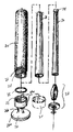
- FIG. 3 is an exploded perspective view of a baton showing the leverage cap of the present invention and a typical known end cap shown in phantom view;
- FIG. 4 is a perspective view of another embodiment of the leverage cap of the present invention.
- FIG. 1 shows a typical baton 10 , which may be similar to a number of batons made by Armament Systems and Procedures, Inc., assignee of the present invention, which batons are described in U.S. Pat. Nos. 5,110,375, 5,149,092, 5,348,297, 5,356,139, 5,645,276 and 5,919,093, and are incorporated herein by reference in their entirety.
- the baton 10 may include three segments, namely an outer segment 20 , a middle segment 28 , and a third or end segment 30 .
- the outer segment 20 has a proximal end 22 having external threads 24 for receiving a leveraged end cap 26 of the present invention.
- the leveraged end cap 26 replaces the known end cap 25 , which is a standard component of commercially available batons.
- the baton 10 further comprises a tip 34 , which is preferably removable, and segment locking means 32 .
- a tip 34 which is preferably removable, and segment locking means 32 .
- a gasket 35 is provided to permit a sealing and well-seated relationship between the baton 10 and the leverage end cap 26 of the present invention.
- FIG. 3 shows assembly of a baton 10 components including details regarding replacement of the known end cap 25 with the leveraged end cap 26 of the present invention. Details of the assembly of baton 10 can be found in the above-cited U.S. patents.
- a baton 10 is shown in a first or retracted position 10 a in phantom lines, and in a second or extended position in solid lines.
- a leverage end cap 26 is attached to the baton 10 by rotatably connecting the internal threads 27 of the end cap to the external threads 24 of the baton.
- the end cap 26 includes a knob portion 26 a , a neck portion 26 b and a connection segment 26 c .
- the knob portion 26 a is generally rounded to provide a comfortable end segment to the baton 10 when gripped by the user. In this way, the user is provided with a smooth end, which is less likely to cause pain or injury if the user accidentally collides therewith. It will be understood that various shapes of the knob 26 a can be adopted without departing from the novel scope of the present invention.
- the knob 26 a may include flattened surface 26 d .
- end cap 36 includes means, such as cut-out or indentation 38 , into which a medallion or seal 40 can be placed for decorative purposes.
- Knob 26 a permits a user's hand 40 to grasp the baton at a location more proximal or lower down along the baton 10 than is possible with batons not utilizing a leverage end cap 26 . As shown in FIG. 2 , the little finger, or pinky, P of the user is placed such that it rests within the double concave or “hour-glass” shaped neck.
- the end cap 26 can be made of the same or similar materials as the baton 10 and/or known cap 25 . Alternatively, it can be formed from other metals, plastics or other materials without departing from the novel scope of the present invention. Further, end cap 26 can be made in a color to match the baton 10 , or can have any color suited to match either uniforms or a preferred color scheme without departing from the novel scope of the present invention.
- the user in operation, the user, after attaching the leveraged end cap 26 , can grasp the baton at a lower position 42 on the outer segment 20 , such that a greater lever arm is created, thus enhancing striking power.
- the user places his little finger, or pinky, P within the hour-glass shaped neck portion 26 b such that a positive grip is established. In this hand position, the user establishes a striking power similar to a longer baton, while maintaining control and having the desirable convenience of using a smaller baton.
- the baton 10 pivots at the location of the little finger P providing f the baton, thus increasing the lever arm of the baton by a length approximately one “hand-width.” Further, as the baton 10 is held such that its proximal end 22 is wrist 44 of the user 40 , a quicker whip like action can be made with the baton, ing power similar to that of a longer baton.
Landscapes
- Engineering & Computer Science (AREA)
- General Engineering & Computer Science (AREA)
- Adornments (AREA)
- Auxiliary Devices For Music (AREA)
Abstract
Description
Claims (4)
Priority Applications (1)
| Application Number | Priority Date | Filing Date | Title |
|---|---|---|---|
| US10/684,970 US7346958B2 (en) | 2003-10-14 | 2003-10-14 | Leveraged baton cap |
Applications Claiming Priority (1)
| Application Number | Priority Date | Filing Date | Title |
|---|---|---|---|
| US10/684,970 US7346958B2 (en) | 2003-10-14 | 2003-10-14 | Leveraged baton cap |
Publications (2)
| Publication Number | Publication Date |
|---|---|
| US20050076473A1 US20050076473A1 (en) | 2005-04-14 |
| US7346958B2 true US7346958B2 (en) | 2008-03-25 |
Family
ID=34423063
Family Applications (1)
| Application Number | Title | Priority Date | Filing Date |
|---|---|---|---|
| US10/684,970 Expired - Lifetime US7346958B2 (en) | 2003-10-14 | 2003-10-14 | Leveraged baton cap |
Country Status (1)
| Country | Link |
|---|---|
| US (1) | US7346958B2 (en) |
Cited By (7)
| Publication number | Priority date | Publication date | Assignee | Title |
|---|---|---|---|---|
| US20110053694A1 (en) * | 2009-08-27 | 2011-03-03 | Wood Robert P | Hand-held anti-assault weapon |
| USD706074S1 (en) * | 2012-07-22 | 2014-06-03 | Allen Chandler Young | Treat maker and pill concealer |
| US8747233B1 (en) | 2012-10-05 | 2014-06-10 | Charles Klein | Grip attachment with LED light for expandable police baton |
| USD710481S1 (en) * | 2013-01-11 | 2014-08-05 | Safariland, Llc | End cap for baton |
| USD763685S1 (en) * | 2015-08-12 | 2016-08-16 | Huitzilo Arriaga | Bottle cap with integrated bottle opener |
| US20170241197A1 (en) * | 2016-02-19 | 2017-08-24 | Hunter Douglas Inc. | Wand for architectural covering |
| US9821936B1 (en) * | 2015-08-12 | 2017-11-21 | Huitzilo Arriaga | Bottle cap with integrated bottle opener |
Citations (31)
| Publication number | Priority date | Publication date | Assignee | Title |
|---|---|---|---|---|
| US83228A (en) * | 1868-10-20 | Improvement in policeman s mace | ||
| US291242A (en) * | 1884-01-01 | John j | ||
| US786040A (en) * | 1904-08-09 | 1905-03-28 | Oscar Liberman | Policeman's mace. |
| US892466A (en) * | 1907-03-19 | 1908-07-07 | Penberthy Injector Co | Closure. |
| US1084969A (en) * | 1913-01-08 | 1914-01-20 | Sargent & Co | Casket-handle. |
| US1496949A (en) * | 1921-11-07 | 1924-06-10 | Ai B Shaw | Stopper for hot-water bottles |
| US2099447A (en) * | 1937-08-20 | 1937-11-16 | Frank A Matsuyama | Police weapon |
| US2266606A (en) * | 1941-04-19 | 1941-12-16 | Frederick D Jones | Patrol stick |
| US2970399A (en) * | 1959-02-26 | 1961-02-07 | Willy O Frohlich | Underwater weapon |
| US3106398A (en) * | 1960-10-18 | 1963-10-08 | Warren Allen Reed | Police weapon |
| US3148406A (en) * | 1962-07-27 | 1964-09-15 | Corning Glass Works | Handle attaching means |
| USD267261S (en) * | 1980-06-19 | 1982-12-14 | Pataluch Casimer J | Exercise bar |
| US4383387A (en) * | 1981-07-30 | 1983-05-17 | Puskar Frank J | Twirling baton |
| US4522398A (en) * | 1983-02-04 | 1985-06-11 | Swartz Franklin J | Police baton |
| USD284553S (en) * | 1984-03-07 | 1986-07-08 | Miles Laboratories, Inc. | Closure for containers |
| US5110375A (en) | 1990-09-20 | 1992-05-05 | Parsons Kevin L | Baton method of heat treating expandable |
| US5149092A (en) | 1991-08-16 | 1992-09-22 | Kevin Parsons | Locking means for extendable baton |
| US5188362A (en) * | 1990-06-20 | 1993-02-23 | Hideyuki Ashihara | Police baton with crosshandle and handguard |
| US5348297A (en) | 1988-10-07 | 1994-09-20 | Parsons Kevin L | Expandable baton with locking joints |
| US5356139A (en) | 1993-01-08 | 1994-10-18 | Armament Systems And Procedures, Inc. | Expandable baton with sections made of dissimilar materials |
| USD351878S (en) * | 1993-02-08 | 1994-10-25 | Globus Karin R | Physical exercise stick |
| US5363285A (en) * | 1993-12-15 | 1994-11-08 | Wideman R Leon | Side handled baton and flashlight assembly |
| US5454565A (en) * | 1994-08-25 | 1995-10-03 | Ramirez; Leonard | Impact weapon structure |
| US5645276A (en) | 1995-03-27 | 1997-07-08 | Armament Systems And Procedures, Inc. | Formed grip for expandable batons |
| US5728003A (en) | 1996-08-27 | 1998-03-17 | Hustad; Gregory B. | Pressure point device |
| US5919093A (en) | 1995-03-27 | 1999-07-06 | Armament Systems & Procedures, Inc. | Formed grip for expandable batons |
| US6135888A (en) | 1998-10-15 | 2000-10-24 | Hindi; Robert C. | Expandable police baton with convenience bulbous handle |
| US6196921B1 (en) * | 1998-12-02 | 2001-03-06 | Randall L. Larson | Interchangeable martial arts weapons system |
| US6261188B1 (en) * | 2000-01-20 | 2001-07-17 | Mark Badura | Expandable baton with handle grip cap |
| USD476568S1 (en) * | 2002-01-23 | 2003-07-01 | Glaxosmithkline Consumer Healthcare | Cap |
| USD503886S1 (en) * | 2003-07-07 | 2005-04-12 | Drug Plastics & Glass Company, Inc. | Bottle cap |
-
2003
- 2003-10-14 US US10/684,970 patent/US7346958B2/en not_active Expired - Lifetime
Patent Citations (31)
| Publication number | Priority date | Publication date | Assignee | Title |
|---|---|---|---|---|
| US83228A (en) * | 1868-10-20 | Improvement in policeman s mace | ||
| US291242A (en) * | 1884-01-01 | John j | ||
| US786040A (en) * | 1904-08-09 | 1905-03-28 | Oscar Liberman | Policeman's mace. |
| US892466A (en) * | 1907-03-19 | 1908-07-07 | Penberthy Injector Co | Closure. |
| US1084969A (en) * | 1913-01-08 | 1914-01-20 | Sargent & Co | Casket-handle. |
| US1496949A (en) * | 1921-11-07 | 1924-06-10 | Ai B Shaw | Stopper for hot-water bottles |
| US2099447A (en) * | 1937-08-20 | 1937-11-16 | Frank A Matsuyama | Police weapon |
| US2266606A (en) * | 1941-04-19 | 1941-12-16 | Frederick D Jones | Patrol stick |
| US2970399A (en) * | 1959-02-26 | 1961-02-07 | Willy O Frohlich | Underwater weapon |
| US3106398A (en) * | 1960-10-18 | 1963-10-08 | Warren Allen Reed | Police weapon |
| US3148406A (en) * | 1962-07-27 | 1964-09-15 | Corning Glass Works | Handle attaching means |
| USD267261S (en) * | 1980-06-19 | 1982-12-14 | Pataluch Casimer J | Exercise bar |
| US4383387A (en) * | 1981-07-30 | 1983-05-17 | Puskar Frank J | Twirling baton |
| US4522398A (en) * | 1983-02-04 | 1985-06-11 | Swartz Franklin J | Police baton |
| USD284553S (en) * | 1984-03-07 | 1986-07-08 | Miles Laboratories, Inc. | Closure for containers |
| US5348297A (en) | 1988-10-07 | 1994-09-20 | Parsons Kevin L | Expandable baton with locking joints |
| US5188362A (en) * | 1990-06-20 | 1993-02-23 | Hideyuki Ashihara | Police baton with crosshandle and handguard |
| US5110375A (en) | 1990-09-20 | 1992-05-05 | Parsons Kevin L | Baton method of heat treating expandable |
| US5149092A (en) | 1991-08-16 | 1992-09-22 | Kevin Parsons | Locking means for extendable baton |
| US5356139A (en) | 1993-01-08 | 1994-10-18 | Armament Systems And Procedures, Inc. | Expandable baton with sections made of dissimilar materials |
| USD351878S (en) * | 1993-02-08 | 1994-10-25 | Globus Karin R | Physical exercise stick |
| US5363285A (en) * | 1993-12-15 | 1994-11-08 | Wideman R Leon | Side handled baton and flashlight assembly |
| US5454565A (en) * | 1994-08-25 | 1995-10-03 | Ramirez; Leonard | Impact weapon structure |
| US5645276A (en) | 1995-03-27 | 1997-07-08 | Armament Systems And Procedures, Inc. | Formed grip for expandable batons |
| US5919093A (en) | 1995-03-27 | 1999-07-06 | Armament Systems & Procedures, Inc. | Formed grip for expandable batons |
| US5728003A (en) | 1996-08-27 | 1998-03-17 | Hustad; Gregory B. | Pressure point device |
| US6135888A (en) | 1998-10-15 | 2000-10-24 | Hindi; Robert C. | Expandable police baton with convenience bulbous handle |
| US6196921B1 (en) * | 1998-12-02 | 2001-03-06 | Randall L. Larson | Interchangeable martial arts weapons system |
| US6261188B1 (en) * | 2000-01-20 | 2001-07-17 | Mark Badura | Expandable baton with handle grip cap |
| USD476568S1 (en) * | 2002-01-23 | 2003-07-01 | Glaxosmithkline Consumer Healthcare | Cap |
| USD503886S1 (en) * | 2003-07-07 | 2005-04-12 | Drug Plastics & Glass Company, Inc. | Bottle cap |
Non-Patent Citations (3)
| Title |
|---|
| Eight (8) pages from http://dtnub.com re Patented Police Products and DTNUB Training dated Feb. 27, 2001 and Mar. 1, 2001. Applicant submits that he was aware of the products shown more than one year prior to the filing of the above-identified patent application. |
| One (1) page (not dated) www. DTNUIB.com advertisement re DTNUB-Stinger / DTNUB = ASPL. Applicant submits that he was aware of the products shown more than one year prior to the filing of the above-identified patent application. |
| One (1) page (not dated) www.DTNIUB.com advertisement re "Less Lethal Force Option That Work!" Applicant submits that he was aware of the products shown more than one year prior to the filing of the above-identified patent application. |
Cited By (8)
| Publication number | Priority date | Publication date | Assignee | Title |
|---|---|---|---|---|
| US20110053694A1 (en) * | 2009-08-27 | 2011-03-03 | Wood Robert P | Hand-held anti-assault weapon |
| USD706074S1 (en) * | 2012-07-22 | 2014-06-03 | Allen Chandler Young | Treat maker and pill concealer |
| US8747233B1 (en) | 2012-10-05 | 2014-06-10 | Charles Klein | Grip attachment with LED light for expandable police baton |
| USD710481S1 (en) * | 2013-01-11 | 2014-08-05 | Safariland, Llc | End cap for baton |
| USD763685S1 (en) * | 2015-08-12 | 2016-08-16 | Huitzilo Arriaga | Bottle cap with integrated bottle opener |
| US9821936B1 (en) * | 2015-08-12 | 2017-11-21 | Huitzilo Arriaga | Bottle cap with integrated bottle opener |
| US20170241197A1 (en) * | 2016-02-19 | 2017-08-24 | Hunter Douglas Inc. | Wand for architectural covering |
| US10538963B2 (en) * | 2016-02-19 | 2020-01-21 | Hunter Douglas Inc | Wand for architectural covering |
Also Published As
| Publication number | Publication date |
|---|---|
| US20050076473A1 (en) | 2005-04-14 |
Similar Documents
| Publication | Publication Date | Title |
|---|---|---|
| US4819137A (en) | Multi-purpose self defense apparatus | |
| US8141547B2 (en) | Crossbow angled grip | |
| US6725545B2 (en) | Kinetic opening folding knife | |
| US4752072A (en) | Telescoping self-defense keychain | |
| US5615662A (en) | Continuous loop wrist strap for bow string release | |
| US8439024B2 (en) | Multi-purpose crossbow cocking device and method | |
| US5188362A (en) | Police baton with crosshandle and handguard | |
| US20020170224A1 (en) | Ergonomic finger grip enhancers for mounting on firearms, sporting implements or hand tools | |
| US7346958B2 (en) | Leveraged baton cap | |
| US4460174A (en) | Self defense weapon | |
| US20050037847A1 (en) | Dual grip walking and defense baton | |
| US3608899A (en) | Hand weapon | |
| JPH04177096A (en) | Grip type body protector | |
| US6761639B2 (en) | Safety baton | |
| US5118108A (en) | Police baton with hand guard and trapping tip | |
| US5728003A (en) | Pressure point device | |
| US5108097A (en) | Multi-functional police baton | |
| US20100077912A1 (en) | Fighting Shield | |
| EP0360005A1 (en) | Crosshandled guard baton (B) | |
| US4498669A (en) | Hand-held defense weapon | |
| US20050083679A1 (en) | Straight handle baton with mushroom cap | |
| US5192075A (en) | Telescoping guard baton with rotatable cross handle | |
| US20050028570A1 (en) | Combination handcuff key and writing instrument | |
| EP0331035B1 (en) | Crosshandled guard baton | |
| EP0378750A1 (en) | Crosshandled guard baton (A) |
Legal Events
| Date | Code | Title | Description |
|---|---|---|---|
| AS | Assignment |
Owner name: ARMAMENT SYSTEMS AND PROCEDURES, INC., WISCONSIN Free format text: ASSIGNMENT OF ASSIGNORS INTEREST;ASSIGNOR:PARSONS, KEVIN L.;REEL/FRAME:015014/0021 Effective date: 20040202 |
|
| STCF | Information on status: patent grant |
Free format text: PATENTED CASE |
|
| AS | Assignment |
Owner name: M&I MARSHALL & ILSLEY BANK, WISCONSIN Free format text: SECURITY AGREEMENT;ASSIGNOR:ARMAMENT SYSTEMS AND PROCEDURES, INC.;REEL/FRAME:021029/0361 Effective date: 20080502 Owner name: M&I MARSHALL & ILSLEY BANK,WISCONSIN Free format text: SECURITY AGREEMENT;ASSIGNOR:ARMAMENT SYSTEMS AND PROCEDURES, INC.;REEL/FRAME:021029/0361 Effective date: 20080502 |
|
| AS | Assignment |
Owner name: EMISSIVE ENERGY CORPORATION, RHODE ISLAND Free format text: SECURITY AGREEMENT;ASSIGNOR:ARMAMENT SYSTEMS AND PROCEDURES, INC.;REEL/FRAME:021064/0057 Effective date: 20080502 Owner name: I.Q. HONG KONG LIMITED, HONG KONG Free format text: SECURITY AGREEMENT;ASSIGNOR:ARMAMENT SYSTEMS AND PROCEDURES, INC.;REEL/FRAME:021064/0057 Effective date: 20080502 Owner name: ZEN DESIGN GROUP LIMITED, MICHIGAN Free format text: SECURITY AGREEMENT;ASSIGNOR:ARMAMENT SYSTEMS AND PROCEDURES, INC.;REEL/FRAME:021064/0057 Effective date: 20080502 Owner name: VECTOR PRODUCTS, INC., FLORIDA Free format text: SECURITY AGREEMENT;ASSIGNOR:ARMAMENT SYSTEMS AND PROCEDURES, INC.;REEL/FRAME:021064/0057 Effective date: 20080502 Owner name: TARGET CORPORATION, MINNESOTA Free format text: SECURITY AGREEMENT;ASSIGNOR:ARMAMENT SYSTEMS AND PROCEDURES, INC.;REEL/FRAME:021064/0057 Effective date: 20080502 Owner name: EMISSIVE ENERGY CORPORATION,RHODE ISLAND Free format text: SECURITY AGREEMENT;ASSIGNOR:ARMAMENT SYSTEMS AND PROCEDURES, INC.;REEL/FRAME:021064/0057 Effective date: 20080502 Owner name: I.Q. HONG KONG LIMITED,HONG KONG Free format text: SECURITY AGREEMENT;ASSIGNOR:ARMAMENT SYSTEMS AND PROCEDURES, INC.;REEL/FRAME:021064/0057 Effective date: 20080502 Owner name: ZEN DESIGN GROUP LIMITED,MICHIGAN Free format text: SECURITY AGREEMENT;ASSIGNOR:ARMAMENT SYSTEMS AND PROCEDURES, INC.;REEL/FRAME:021064/0057 Effective date: 20080502 Owner name: VECTOR PRODUCTS, INC.,FLORIDA Free format text: SECURITY AGREEMENT;ASSIGNOR:ARMAMENT SYSTEMS AND PROCEDURES, INC.;REEL/FRAME:021064/0057 Effective date: 20080502 Owner name: TARGET CORPORATION,MINNESOTA Free format text: SECURITY AGREEMENT;ASSIGNOR:ARMAMENT SYSTEMS AND PROCEDURES, INC.;REEL/FRAME:021064/0057 Effective date: 20080502 |
|
| AS | Assignment |
Owner name: ARMAMENT SYSTEMS AND PROCEDURES, INC., WISCONSIN Free format text: RELEASE BY SECURED PARTY;ASSIGNORS:EMISSIVE ENERGY COPRORATION;I.Q. HONG KONG LIMITED;ZEN DESIGN GROUP LIMITED;AND OTHERS;REEL/FRAME:026877/0699 Effective date: 20110725 |
|
| FPAY | Fee payment |
Year of fee payment: 4 |
|
| FPAY | Fee payment |
Year of fee payment: 8 |
|
| MAFP | Maintenance fee payment |
Free format text: PAYMENT OF MAINTENANCE FEE, 12TH YR, SMALL ENTITY (ORIGINAL EVENT CODE: M2553); ENTITY STATUS OF PATENT OWNER: SMALL ENTITY Year of fee payment: 12 |