US7331069B2 - Water-saving flush toilet - Google Patents
Water-saving flush toilet Download PDFInfo
- Publication number
- US7331069B2 US7331069B2 US10/955,895 US95589504A US7331069B2 US 7331069 B2 US7331069 B2 US 7331069B2 US 95589504 A US95589504 A US 95589504A US 7331069 B2 US7331069 B2 US 7331069B2
- Authority
- US
- United States
- Prior art keywords
- water
- bowl
- flush toilet
- saving flush
- lever
- Prior art date
- Legal status (The legal status is an assumption and is not a legal conclusion. Google has not performed a legal analysis and makes no representation as to the accuracy of the status listed.)
- Expired - Fee Related, expires
Links
- XLYOFNOQVPJJNP-UHFFFAOYSA-N water Substances O XLYOFNOQVPJJNP-UHFFFAOYSA-N 0.000 claims abstract description 62
- 239000010865 sewage Substances 0.000 claims abstract description 21
- 238000007789 sealing Methods 0.000 claims description 2
- 239000004033 plastic Substances 0.000 abstract description 4
- 238000007599 discharging Methods 0.000 description 12
- 238000011010 flushing procedure Methods 0.000 description 8
- 239000007789 gas Substances 0.000 description 4
- 239000002699 waste material Substances 0.000 description 3
- XLYOFNOQVPJJNP-ZSJDYOACSA-N Heavy water Chemical compound [2H]O[2H] XLYOFNOQVPJJNP-ZSJDYOACSA-N 0.000 description 2
- 230000002950 deficient Effects 0.000 description 2
- 210000003608 fece Anatomy 0.000 description 2
- NLYAJNPCOHFWQQ-UHFFFAOYSA-N kaolin Chemical compound O.O.O=[Al]O[Si](=O)O[Si](=O)O[Al]=O NLYAJNPCOHFWQQ-UHFFFAOYSA-N 0.000 description 2
- 239000003595 mist Substances 0.000 description 2
- 230000000903 blocking effect Effects 0.000 description 1
- 238000004140 cleaning Methods 0.000 description 1
- 230000007797 corrosion Effects 0.000 description 1
- 238000005260 corrosion Methods 0.000 description 1
- 201000010099 disease Diseases 0.000 description 1
- 208000037265 diseases, disorders, signs and symptoms Diseases 0.000 description 1
- 230000007613 environmental effect Effects 0.000 description 1
- 238000009434 installation Methods 0.000 description 1
- 238000012423 maintenance Methods 0.000 description 1
- 239000007769 metal material Substances 0.000 description 1
- 238000005381 potential energy Methods 0.000 description 1
- 239000011347 resin Substances 0.000 description 1
- 229920005989 resin Polymers 0.000 description 1
- 238000005507 spraying Methods 0.000 description 1
- 238000005406 washing Methods 0.000 description 1
Images


Classifications
-
- E—FIXED CONSTRUCTIONS
- E03—WATER SUPPLY; SEWERAGE
- E03D—WATER-CLOSETS OR URINALS WITH FLUSHING DEVICES; FLUSHING VALVES THEREFOR
- E03D11/00—Other component parts of water-closets, e.g. noise-reducing means in the flushing system, flushing pipes mounted in the bowl, seals for the bowl outlet, devices preventing overflow of the bowl contents; devices forming a water seal in the bowl after flushing, devices eliminating obstructions in the bowl outlet or preventing backflow of water and excrements from the waterpipe
- E03D11/02—Water-closet bowls ; Bowls with a double odour seal optionally with provisions for a good siphonic action; siphons as part of the bowl
- E03D11/10—Bowls with closure elements provided between bottom or outlet and the outlet pipe; Bowls with pivotally supported inserts
Definitions
- the present invention is related to a sanitary installation, specifically to a water-saving flush toilet.
- the current flush toilet always uses a siphon pipe to suck/discharge a sewage and to isolate the smell gas.
- water is firstly filled into the water tank to replenish as a level to the top of the siphon pipe.
- discharging a large amount of water to expel the air in a water discharging pipe of the siphon pipe in order to form vacuum such that a pressure difference is produced between both ends.
- sewage together with water is discharged into a sewage-discharging pipe by the atmosphere pressure.
- the sewage in the flush toilet bowl is sucked into the sewage-discharging pipe and discharged by the sewage-discharging pipe.
- Another function of the siphon pipe is to retain water below a level of the top of the siphon pipe to isolate the smell gases flowing into a room so as to keep the flesh and clean of the air in said room.
- the current siphon pipe type flush toilet must be provided with a water tank to store a large amount of water to be flush out in a short period so as to generate vacuum in the siphon pipe. If there is no water tank, it still is possible to form vacuum in the discharging end of the siphon pipe for the high-pressure water source, but does not work for a low-pressure water source. That is, the amount of flushing water is not enough to expel all air in the discharging pipe. In the other words, the replenishing water is not as fast as the discharging water. For the high-pressure water source, although it is possible to provide a large amount of water to form the vacuum in the siphon pipe, the discharged water should be deemed as waste.
- the object of the present invention is to provide an improved water-saving flush toilet to solve the problem of heavy water consumption and the waste of water resource for the current siphon of the pipe flush toilet.
- a water-saving flush toilet comprising a bowl having a seat and a sewage discharge port, characterized in that a siphon pipe is omitted at the rear of a sewage discharge pipe of the bowl, a discharge seal valve is arranged at the sewage discharge port, the discharge seal valve together with a valve cover are arranged at a valve seat, a water tap handle at the lower of the bowl is provided with a lever, a cord is connected between a handle of the valve cover and a joint of the bowl, said cord is connected to hang a weight via another joint of the bowl while another end of the lever is connected to another cord and also connected to said weight via said two joints; the upper of the bowl is arranged with a water channel and a sprinkler head, an open of said water channel connected to the water tap at the lower of the bowl via a connecting plastic tube, water pipes are arranged respectively at the upper and the lower of the bowl without any water tank.
- Water-saving flush toilet of the present invention is adapted to a motor or foot-operated flush toilet to avoid or eliminate disease spreading via touching by hand. If it is motorized, the flushing is automated finished once by pressing a button. Said button can be installed on the top of the storage bin or just on the ground. Said motor is suitable to be operated at a 20V for safety reason.
- a water tank is omitted in this present invention and the cost is lowered as well as increasing the space of the cleaning room. Moreover, it can be replaced by a pleasing design storage bin for sanitary accessories to be used conveniently.
- the filling time of water tank in a traditional flush toilet is generally takes for 1 to 5 minutes, while the flushing time for the present water-saving flush toilet is only 2 seconds without the filling of water tank, which obviously saves time in flushing and water used.
- the present invention can be used in water-deficient areas, an auxiliary used water tank can be connected to the water inlet so as to fully utilize used water such as water from cloth-washing or cleansing.
- metal material should be avoided to be used as the parts in the present invention for preventing corrosion that the working life could be improved.
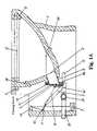
- FIG. 1 is a schematic structure view of a water-saving flush toilet with a storage bin
- FIG. 1A is a schematic structure view of a water-saving flush toilet with a closing cover
- FIG. 2A illustrates the routing of a cable connecting a lever with a weight
- FIG. 2B illustrates the routing of a cable connecting a lever with a valve cover.
- the present invention is a water-saving flush toilet that is a bowl 1 having a seat and a sewage discharge port 2 .
- the bowl 1 is made of resin porcelain clay or porcelain clay.
- a siphon pipe is omitted at the rear of a sewage discharge pipe of the bowl.
- a discharge seal valve 3 is arranged at the sewage discharge port 2 .
- the discharge seal valve 3 may be arranged at the front end or rear end of the lower portion of the bowl 1 .
- the sewage discharge port 2 would be out of sight if the discharge seal valve 3 is arranged at the bottom end of the lower portion of the bowl 1 , so that it is pleasing and generous in sight.
- the discharge seal valve 3 together with a valve cover 31 are arranged at a valve seat 4 .
- a handle of a water tap 10 at the lower of the bowl is provided with a lever 5 .
- a cord 61 is connected between a handle 32 of the valve cover 31 and a joint 11 of the bowl, said cord 61 is connected to lever 5 .
- Lever 5 is connected to another cord 62 that is also connected to weight 7 via two joints 11 , 12 .
- a magnetic attaching device 33 and a rubber seal ring 34 are provided on the valve cover 31 of the discharge seal valve 3 . During the use, the magnetic attaching device 33 and/or the weight 7 is to ensure the rubber seal ring 34 to trap water and the valve cover 31 to be closed tightly. In this way, a certain level of water is maintained inside the flush toilet to isolate two ends. No smell gas can be given off from the sewage discharge pipe into the indoor, so flushing and smell blocking is guaranteed.
- the upper of the bowl 1 is arranged with a water channel 13 and a sprinkler head 8 , an open of said water channel is connected to the water tap 10 at the lower of the bowl via a connecting plastic tube 9 .
- the sprinkler head 8 is a sector-shaped sprinkler head for flushing feces.
- Water pipes are arranged respectively at the upper and the lower of the bowl without any water tank. Water pipes of diameter 1.2 inch ( ⁇ 12.7 mm) can be used.
- a lower water pipe 21 has one end connected to water supply pip and another end connected to the water tap 10 via a tee joint 22 .
- the lower portion inside the bowl 1 is also provided with another sprinkler head 23 .
- Said sprinkler head 23 may be a cylindrical sprinkler head for flushing feces, too.
- the upper portion of the bowl 1 is provided with a sprinkler head or mist head 24 for spraying human body. Said sprinkler head or mist head 24 can be redirected in two dimension of 100 degree.
- a closing cover shown in FIG. 1A and/or a storage bin shown in FIG. 1 can be mounted at the upper end of the bowl 1 for facilitating in maintenance.
- the weight can also be hanged on the valve cover 31 of the discharge seal valve so that the rubber seal ring be tightly pressed to prevent smell gas flowing out.
Landscapes
- Health & Medical Sciences (AREA)
- Life Sciences & Earth Sciences (AREA)
- Engineering & Computer Science (AREA)
- Hydrology & Water Resources (AREA)
- Public Health (AREA)
- Water Supply & Treatment (AREA)
- Sanitary Device For Flush Toilet (AREA)
Abstract
A water-saving flush toilet is disclosed. A discharge seal valve is arranged at a sewage discharge port, a discharge seal valve together with a valve cover are arranged at a valve seat. A water tap handle at the lower of the bowl is provided with a lever, a cord is connected between a handle of the valve cover and the lever via a joint of the bowl. The lever is also connected to another cord that is connected to a weight via said two joints. The upper of the bowl is arranged with a water channel and a sprinkler head, an open of said water channel connected to the water tap at the lower of the bowl via a connecting plastic tube, water pipes are arranged respectively at the upper and the lower of the bowl without any water tank.
Description
The present invention is related to a sanitary installation, specifically to a water-saving flush toilet.
The current flush toilet always uses a siphon pipe to suck/discharge a sewage and to isolate the smell gas. During the discharging, water is firstly filled into the water tank to replenish as a level to the top of the siphon pipe. When discharging a large amount of water to expel the air in a water discharging pipe of the siphon pipe in order to form vacuum such that a pressure difference is produced between both ends. Finally, sewage together with water is discharged into a sewage-discharging pipe by the atmosphere pressure. In regard to the sewage-discharging pipe, the sewage in the flush toilet bowl is sucked into the sewage-discharging pipe and discharged by the sewage-discharging pipe.
The higher the top of the siphon pipe in the water tank, the larger the diameters of sewage discharging pipe, then the more water needed in generating the vacuum. Since the water needed is to generate the vacuum only, water is a “pro-waste” for this single purpose on discharging sewage. It is a disadvantage in the environmental protection and in the full utilization of water resource. Especially, it should be fonder of water in water-deficient areas. Another function of the siphon pipe is to retain water below a level of the top of the siphon pipe to isolate the smell gases flowing into a room so as to keep the flesh and clean of the air in said room.
The current siphon pipe type flush toilet must be provided with a water tank to store a large amount of water to be flush out in a short period so as to generate vacuum in the siphon pipe. If there is no water tank, it still is possible to form vacuum in the discharging end of the siphon pipe for the high-pressure water source, but does not work for a low-pressure water source. That is, the amount of flushing water is not enough to expel all air in the discharging pipe. In the other words, the replenishing water is not as fast as the discharging water. For the high-pressure water source, although it is possible to provide a large amount of water to form the vacuum in the siphon pipe, the discharged water should be deemed as waste.
The object of the present invention is to provide an improved water-saving flush toilet to solve the problem of heavy water consumption and the waste of water resource for the current siphon of the pipe flush toilet.
The technical solution of the present invention as follows:
It is to provide a water-saving flush toilet, comprising a bowl having a seat and a sewage discharge port, characterized in that a siphon pipe is omitted at the rear of a sewage discharge pipe of the bowl, a discharge seal valve is arranged at the sewage discharge port, the discharge seal valve together with a valve cover are arranged at a valve seat, a water tap handle at the lower of the bowl is provided with a lever, a cord is connected between a handle of the valve cover and a joint of the bowl, said cord is connected to hang a weight via another joint of the bowl while another end of the lever is connected to another cord and also connected to said weight via said two joints; the upper of the bowl is arranged with a water channel and a sprinkler head, an open of said water channel connected to the water tap at the lower of the bowl via a connecting plastic tube, water pipes are arranged respectively at the upper and the lower of the bowl without any water tank.
Water-saving flush toilet of the present invention is adapted to a motor or foot-operated flush toilet to avoid or eliminate disease spreading via touching by hand. If it is motorized, the flushing is automated finished once by pressing a button. Said button can be installed on the top of the storage bin or just on the ground. Said motor is suitable to be operated at a 20V for safety reason.
A water tank is omitted in this present invention and the cost is lowered as well as increasing the space of the cleaning room. Moreover, it can be replaced by a pleasing design storage bin for sanitary accessories to be used conveniently. The filling time of water tank in a traditional flush toilet is generally takes for 1 to 5 minutes, while the flushing time for the present water-saving flush toilet is only 2 seconds without the filling of water tank, which obviously saves time in flushing and water used.
The present invention can be used in water-deficient areas, an auxiliary used water tank can be connected to the water inlet so as to fully utilize used water such as water from cloth-washing or cleansing.
If it is possible, metal material should be avoided to be used as the parts in the present invention for preventing corrosion that the working life could be improved.
With reference to FIG. 1 , the present invention is a water-saving flush toilet that is a bowl 1 having a seat and a sewage discharge port 2. The bowl 1 is made of resin porcelain clay or porcelain clay. A siphon pipe is omitted at the rear of a sewage discharge pipe of the bowl. A discharge seal valve 3 is arranged at the sewage discharge port 2. The discharge seal valve 3 may be arranged at the front end or rear end of the lower portion of the bowl 1. The sewage discharge port 2 would be out of sight if the discharge seal valve 3 is arranged at the bottom end of the lower portion of the bowl 1, so that it is pleasing and generous in sight.
The discharge seal valve 3 together with a valve cover 31 are arranged at a valve seat 4. A handle of a water tap 10 at the lower of the bowl is provided with a lever 5. A cord 61 is connected between a handle 32 of the valve cover 31 and a joint 11 of the bowl, said cord 61 is connected to lever 5. Lever 5 is connected to another cord 62 that is also connected to weight 7 via two joints 11, 12. A magnetic attaching device 33 and a rubber seal ring 34 are provided on the valve cover 31 of the discharge seal valve 3. During the use, the magnetic attaching device 33 and/or the weight 7 is to ensure the rubber seal ring 34 to trap water and the valve cover 31 to be closed tightly. In this way, a certain level of water is maintained inside the flush toilet to isolate two ends. No smell gas can be given off from the sewage discharge pipe into the indoor, so flushing and smell blocking is guaranteed.
The upper of the bowl 1 is arranged with a water channel 13 and a sprinkler head 8, an open of said water channel is connected to the water tap 10 at the lower of the bowl via a connecting plastic tube 9. The sprinkler head 8 is a sector-shaped sprinkler head for flushing feces. Water pipes are arranged respectively at the upper and the lower of the bowl without any water tank. Water pipes of diameter 1.2 inch (˜12.7 mm) can be used. A lower water pipe 21 has one end connected to water supply pip and another end connected to the water tap 10 via a tee joint 22.
The lower portion inside the bowl 1 is also provided with another sprinkler head 23. Said sprinkler head 23 may be a cylindrical sprinkler head for flushing feces, too. The upper portion of the bowl 1 is provided with a sprinkler head or mist head 24 for spraying human body. Said sprinkler head or mist head 24 can be redirected in two dimension of 100 degree.
A closing cover shown in FIG. 1A and/or a storage bin shown in FIG. 1 can be mounted at the upper end of the bowl 1 for facilitating in maintenance.
In use of the present invention for flushing sewage, water is trapped when the discharge seal valve is closed, and water is flushed when the discharge seal valve is open. When the handle of a water tap is pressed by foot, water is passing water pipes of diameter 1.2 inch (˜12.7 mm) and the connecting plastic tube into the water channel of the bowl. Dirt is washed out by one or two sprinkler heads into the sewage discharge port and sewage discharge main pipe. In that time, the lever of the handle is connected with the two cords, one is to open the discharge seal valve, another is to raise the weight to have potential energy. After water is completely flushed, the weight will be descending to close the water tap via the lever. The valve cover will be closed automatically and is finally closed tightly under the action of magnetic attaching device to be water sealing.
In the present invention, the weight can also be hanged on the valve cover 31 of the discharge seal valve so that the rubber seal ring be tightly pressed to prevent smell gas flowing out.
Claims (9)
1. A water-saving flush toilet, comprising:
a bowl having a seat and a sewage discharge port;
a discharge seal valve having a valve cover arranged at the sewage discharge port;
a water tap handle having a lever;
a first cord connecting the valve cover and the lever, the first cord passing through a first joint; and
a second cord connecting the lever and a weight, the second cord passing through the first joint and a second joint.
2. The water-saving flush toilet of claim 1 , further comprising a first sprinkler arranged in the lower portion of the bowl.
3. The water-saving flush toilet of claim 1 , further comprising a second sprinkler arranged in the upper portion of the bowl.
4. The water-saving flush toilet of claim 1 further comprising a magnetic attaching device for providing sealing between the sewage discharge port and the discharge seal valve.
5. The water-saving flush toilet of claim 1 further comprising a rubber seal between the sewage discharge port and the discharge seal valve.
6. The water-saving flush toilet of claim 1 further comprising a closing cover.
7. The water-saving flush toilet of claim 1 further comprising a storage bin.
8. The water-saving flush toilet of claim 1 further comprising a water channel arranged in the rim of the bowl.
9. The water-saving flush toilet of claim 8 , wherein the water channel is connected to a water tap.
Applications Claiming Priority (2)
| Application Number | Priority Date | Filing Date | Title |
|---|---|---|---|
| CNU2004200197863U CN2672179Y (en) | 2004-01-21 | 2004-01-21 | Water saving type flushing toilet |
| CN200420019786.3 | 2004-01-21 |
Publications (2)
| Publication Number | Publication Date |
|---|---|
| US20050155143A1 US20050155143A1 (en) | 2005-07-21 |
| US7331069B2 true US7331069B2 (en) | 2008-02-19 |
Family
ID=34483209
Family Applications (1)
| Application Number | Title | Priority Date | Filing Date |
|---|---|---|---|
| US10/955,895 Expired - Fee Related US7331069B2 (en) | 2004-01-21 | 2004-09-30 | Water-saving flush toilet |
Country Status (2)
| Country | Link |
|---|---|
| US (1) | US7331069B2 (en) |
| CN (1) | CN2672179Y (en) |
Cited By (2)
| Publication number | Priority date | Publication date | Assignee | Title |
|---|---|---|---|---|
| US20070245475A1 (en) * | 2006-04-19 | 2007-10-25 | Lucent Technologies Inc. | Toilet Tank Flush Valve with Magnetically Assisted Closure |
| US20100319117A1 (en) * | 2006-10-24 | 2010-12-23 | Nir Abadi | Toilet flushing without using a toilet tank |
Families Citing this family (11)
| Publication number | Priority date | Publication date | Assignee | Title |
|---|---|---|---|---|
| US20080276362A1 (en) * | 2007-05-10 | 2008-11-13 | O'malley Conor | Mechanically sealable rapid opening stagger-flush residential toilet |
| GB0722735D0 (en) * | 2007-11-20 | 2008-01-02 | Straight Flush Ltd | Water conserving toilet |
| US8555428B2 (en) * | 2009-11-17 | 2013-10-15 | Kohler Co. | Plumbing fixture with flush valve actuator and methods of calibrating same |
| CN103104019A (en) * | 2011-11-10 | 2013-05-15 | 郭志刚 | Strong suction tube |
| CN102704560B (en) * | 2012-07-03 | 2013-12-25 | 吴明科 | Organ pipe straight-way type spray-proof energy-saving toilet |
| CN104018568A (en) * | 2014-05-07 | 2014-09-03 | 徐长秋 | Silicone, rubber, excretion valve and eccentric water tank and toilet |
| CN104264761A (en) * | 2014-08-21 | 2015-01-07 | 陈绪强 | Non-blocking washdown water-saving toilet |
| CN106836425B (en) * | 2017-02-21 | 2022-07-05 | 臧铁钢 | Double-door micro-sound micro-water-volume spiral torrent closed type sewage discharge sanitary flush toilet |
| CN108316428A (en) * | 2017-08-30 | 2018-07-24 | 吴小再 | User can be improved to go to the toilet the squatting pan of experience |
| CN108118766A (en) * | 2017-12-15 | 2018-06-05 | 广州市首试科技有限公司 | Anti-suck-back structure of intelligent toilet lid |
| CN114568926B (en) * | 2022-03-07 | 2023-11-24 | 海信家电集团股份有限公司 | Steaming and baking equipment and control method thereof |
Citations (6)
| Publication number | Priority date | Publication date | Assignee | Title |
|---|---|---|---|---|
| US116086A (en) * | 1871-06-20 | Improvement in water-supply attachments to wash-basins | ||
| US196721A (en) * | 1877-10-30 | Improvement in water-closets | ||
| US251813A (en) * | 1882-01-03 | Water-closet | ||
| US280017A (en) * | 1883-06-26 | button | ||
| US418580A (en) * | 1889-12-31 | William s | ||
| US3798681A (en) * | 1972-01-10 | 1974-03-26 | O Johansen | Device in water closets |
-
2004
- 2004-01-21 CN CNU2004200197863U patent/CN2672179Y/en not_active Expired - Fee Related
- 2004-09-30 US US10/955,895 patent/US7331069B2/en not_active Expired - Fee Related
Patent Citations (6)
| Publication number | Priority date | Publication date | Assignee | Title |
|---|---|---|---|---|
| US116086A (en) * | 1871-06-20 | Improvement in water-supply attachments to wash-basins | ||
| US196721A (en) * | 1877-10-30 | Improvement in water-closets | ||
| US251813A (en) * | 1882-01-03 | Water-closet | ||
| US280017A (en) * | 1883-06-26 | button | ||
| US418580A (en) * | 1889-12-31 | William s | ||
| US3798681A (en) * | 1972-01-10 | 1974-03-26 | O Johansen | Device in water closets |
Cited By (3)
| Publication number | Priority date | Publication date | Assignee | Title |
|---|---|---|---|---|
| US20070245475A1 (en) * | 2006-04-19 | 2007-10-25 | Lucent Technologies Inc. | Toilet Tank Flush Valve with Magnetically Assisted Closure |
| US20100319117A1 (en) * | 2006-10-24 | 2010-12-23 | Nir Abadi | Toilet flushing without using a toilet tank |
| US8307470B2 (en) * | 2006-10-24 | 2012-11-13 | Oved Abadi | Toilet flushing without using a toilet tank |
Also Published As
| Publication number | Publication date |
|---|---|
| US20050155143A1 (en) | 2005-07-21 |
| CN2672179Y (en) | 2005-01-19 |
Similar Documents
| Publication | Publication Date | Title |
|---|---|---|
| US7331069B2 (en) | Water-saving flush toilet | |
| KR101163357B1 (en) | Water-saving toilet | |
| US8082605B2 (en) | Low flow hygienic apparatus and methods | |
| US20070113331A1 (en) | Method of operating a multi-phase, high energy flushing system for optimal waste removal and bowl cleaning within a prescribed water consumption range | |
| CN102864830A (en) | Water-saving, uneasily blocked and automatic high pressure flush closet | |
| US7103925B2 (en) | Odor eliminating system for a toilet, toilet including the odor eliminating system, and toilet seat assembly | |
| US12435500B2 (en) | Flushing method for toilet, and flushing toilet | |
| US20190242104A1 (en) | High-pressure water-saving closestool | |
| CN105696668A (en) | Electronic toilet based on separately electronic and manual control | |
| CN116876622B (en) | Multifunctional water-saving closestool | |
| CN101205733B (en) | Non-tank water-saving toilet seat | |
| KR102626578B1 (en) | Apparatus removing stink in toilet bowl of straight buried water supply type | |
| CN203741967U (en) | Water and air linkage squatting pan | |
| CN104929219B (en) | Water gas linkage squatting pan | |
| CN201679064U (en) | Odorless water-saving toilet bowl | |
| CN207436154U (en) | A kind of intellectual water closet with water pump | |
| KR101985189B1 (en) | Vacuum Absorbing Type Toilet Stool | |
| KR20160115600A (en) | Exterior fan type deodorizing Toilet Seat Features a Flush using excrete trap | |
| CN202248193U (en) | Squatting pan with antisticking base wad | |
| CN2892995Y (en) | A household cleaning water reuse device | |
| CN203412074U (en) | Anti-blocking water closet | |
| CN201554102U (en) | Tankless intelligent water-saving toilet | |
| CN111877488B (en) | Intelligent closestool | |
| CN2732862Y (en) | Water-saving flushing device for closet | |
| CN2488969Y (en) | Water saving device for domestic toilet |
Legal Events
| Date | Code | Title | Description |
|---|---|---|---|
| REMI | Maintenance fee reminder mailed | ||
| LAPS | Lapse for failure to pay maintenance fees | ||
| STCH | Information on status: patent discontinuation |
Free format text: PATENT EXPIRED DUE TO NONPAYMENT OF MAINTENANCE FEES UNDER 37 CFR 1.362 |
|
| FP | Expired due to failure to pay maintenance fee |
Effective date: 20120219 |