US73180A - In straw-cutters - Google Patents
In straw-cutters Download PDFInfo
- Publication number
- US73180A US73180A US73180DA US73180A US 73180 A US73180 A US 73180A US 73180D A US73180D A US 73180DA US 73180 A US73180 A US 73180A
- Authority
- US
- United States
- Prior art keywords
- frame
- sliding
- attached
- knife
- feed
- Prior art date
- Legal status (The legal status is an assumption and is not a legal conclusion. Google has not performed a legal analysis and makes no representation as to the accuracy of the status listed.)
- Expired - Lifetime
Links
- 239000010902 straw Substances 0.000 description 2
- 238000010276 construction Methods 0.000 description 1
Images
Classifications
-
- B—PERFORMING OPERATIONS; TRANSPORTING
- B23—MACHINE TOOLS; METAL-WORKING NOT OTHERWISE PROVIDED FOR
- B23D—PLANING; SLOTTING; SHEARING; BROACHING; SAWING; FILING; SCRAPING; LIKE OPERATIONS FOR WORKING METAL BY REMOVING MATERIAL, NOT OTHERWISE PROVIDED FOR
- B23D31/00—Shearing machines or shearing devices covered by none or more than one of the groups B23D15/00 - B23D29/00; Combinations of shearing machines
- B23D31/002—Breaking machines, i.e. pre-cutting and subsequent breaking
-
- B—PERFORMING OPERATIONS; TRANSPORTING
- B26—HAND CUTTING TOOLS; CUTTING; SEVERING
- B26D—CUTTING; DETAILS COMMON TO MACHINES FOR PERFORATING, PUNCHING, CUTTING-OUT, STAMPING-OUT OR SEVERING
- B26D3/00—Cutting work characterised by the nature of the cut made; Apparatus therefor
- B26D3/003—Cutting work characterised by the nature of the cut made; Apparatus therefor specially adapted for cutting rubber
- B26D3/005—Cutting work characterised by the nature of the cut made; Apparatus therefor specially adapted for cutting rubber for cutting used tyres
Definitions
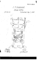
- Figure l is aside view of my improved machine.
- Figure 2 isfront view of the same.
- Figure 3 is a. vertical'longitudinal section of the same, taken throughthe line a: x, iig. 2.
- Figure 4 is a" vertical cross-section of the same, taken through the line y y, fig. 1.
- My invontion has for its object to furnish an improved hay-cutter, ,which shall be self-feeding and doubloacting, and which will do itswork quicker and betterithan the hay-cutters now in general use and it consists in the combination and arrangement of the bevelled knives with the sliding frame and feedbox, and inM the combina.- tion. of the slotted arms or levers, sliding frame, and sliding rake-head, with each other and with thefeed-boi and sliding knife-frame; the whole being constructed and arranged as hereinafter morofnlly described. j
- .A is the foundation-frame of thejmachine.
- B is a vertical'frame, to which theforward end'ofthe feed-box C is attached, and within which the knife-frameD slides up and down.
- To the centre. of the upper end of the sliding knife-frame D is pivoted the lower end of the connecting-rod E, the upper end-of which is pivoted tothe crank'formed upon the shaft F,whieh revolves in bearings in the upper end of th frame B.
- 'To oneiend'of the shaft-E is attacheda fly-wheel, G, and to its other end c small bevel-gear wheel, H, th e teetliiof which mesh into the teeth ofthe larger gear-wheel I attached to the shaft J.
- the shaftJ revolves in bearings'attached vto the frameB, and to its end, orto the geur-wheel I, is attached the crank K, by which the machineis operated.
- -L is a knife attached to the-rear' side of the central part of'the frame D, and both the upper and' lower edges of which are bevelled, as shown in iig. 2, and have cuttingedges formed upon them.
- l M and are ,knives attached tothe forward end or mouth 'of the fe-edboi'r C or to the vertical frame B.
- the lower edge of the knife M andthe upper edge of the knifeN are bevelled to correspond with the' knife L, so that a cut may be made upon the upward as well as upon the'downwad movementl of the knife-frame D".
- S are rakefheads, sliding verticallyin grooves in the sliding frames O, the Ateeth of which pass through and work inslots in the top and bottom ofthe feed-box C.
- To the inner sides of the vertical arms of the rake-heads-S are attached pins, which enter slots .in the levers or arms T, by means of which the rake-headsare withdrawn from or forced forward into the feed-.box C.
- the lever-armsT are pivoted to supports attached to the cross-bars b of vthe frame B, and their endsproject forward, so as to b e struck and operated to raise and lower the rake-heads at the proper time by the catches or stops U pivoted to the sliding knife-frame D.
- the rake-heads S, vertical frames Q, lever-arms R'and T, stop and spring-stops or catches U V, are sc arranged that the onel rake-headis withdrawn-from the feed-box and moved back, while the-other is thrust into the said feed-box andis feeding'the hay or straw forward to the knives.y I I I claimfasvnew, and desire to secure by Letters Patent-- 1.
Landscapes
- Engineering & Computer Science (AREA)
- Mechanical Engineering (AREA)
- Life Sciences & Earth Sciences (AREA)
- Forests & Forestry (AREA)
- Harvester Elements (AREA)
Description
@with 'uiteten 'atrnt @ffice J. F. HAMMOND, OF SUDBURY, .MASSACHUSETTS.iV
Letters Patent No. 73,180,d atcd January. 7, 1868.
T0 ALL WHOM IT'MAY CONCERN:
Be it known that I, J. F. YHAMMOND, of VNorth Sudbury, in thc'county of Middlesex, and State of Massachusetts, have invented n new and improvedSelf-Feeding Double-Action-BevclledKnife Hay-Cutter; and I do hereby declare that the following is a'full, clear, and exact description thereof, which lwill enable others 'skilledin the art to make and use the same, reference being had to the accompanying drawings, forming partof lthis specification.
Figure l is aside view of my improved machine.
Figure 2 isfront view of the same.
Figure 3 is a. vertical'longitudinal section of the same, taken throughthe line a: x, iig. 2.
Figure 4 is a" vertical cross-section of the same, taken through the line y y, fig. 1.
Similar letters ofreferen'ce indicate corresponding parts.
.My invontion has for its object to furnish an improved hay-cutter, ,which shall be self-feeding and doubloacting, and which will do itswork quicker and betterithan the hay-cutters now in general use and it consists in the combination and arrangement of the bevelled knives with the sliding frame and feedbox, and inM the combina.- tion. of the slotted arms or levers, sliding frame, and sliding rake-head, with each other and with thefeed-boi and sliding knife-frame; the whole being constructed and arranged as hereinafter morofnlly described. j
.Ais the foundation-frame of thejmachine. B is a vertical'frame, to which theforward end'ofthe feed-box C is attached, and within which the knife-frameD slides up and down. To the centre. of the upper end of the sliding knife-frame D is pivoted the lower end of the connecting-rod E, the upper end-of which is pivoted tothe crank'formed upon the shaft F,whieh revolves in bearings in the upper end of th frame B. 'To oneiend'of the shaft-E is attacheda fly-wheel, G, and to its other end c small bevel-gear wheel, H, th e teetliiof which mesh into the teeth ofthe larger gear-wheel I attached to the shaft J. The shaftJ revolves in bearings'attached vto the frameB, and to its end, orto the geur-wheel I, is attached the crank K, by which the machineis operated.
-L is a knife attached to the-rear' side of the central part of'the frame D, and both the upper and' lower edges of which are bevelled, as shown in iig. 2, and have cuttingedges formed upon them.l M and are ,knives attached tothe forward end or mouth 'of the fe-edboi'r C or to the vertical frame B. The lower edge of the knife M andthe upper edge of the knifeN are bevelled to correspond with the' knife L, so that a cut may be made upon the upward as well as upon the'downwad movementl of the knife-frame D". Oare vertical frames sliding upon the guide-rods P, secured to supports `attached to the top'and bottom of the forward partof'tho feed-box C, as shown in'figs. 1, 3, and 4. '.lo the ends of the frames O are'attached pins, which enter `slots in ,the arms" R, by which the said frames are moved back and forth. The slotted lever-arms R are pivotcd to the inner sides of the frame B, and their ends project forward, so as to be struck and'operated, at the proper time to move the said framesO, by stop-pins attached to the sliding knife-frame D. S are rakefheads, sliding verticallyin grooves in the sliding frames O, the Ateeth of which pass through and work inslots in the top and bottom ofthe feed-box C. To the inner sides of the vertical arms of the rake-heads-S are attached pins, which enter slots .in the levers or arms T, by means of which the rake-headsare withdrawn from or forced forward into the feed-.box C. The lever-armsT are pivoted to supports attached to the cross-bars b of vthe frame B, and their endsproject forward, so as to b e struck and operated to raise and lower the rake-heads at the proper time by the catches or stops U pivoted to the sliding knife-frame D. 'V are springs passing around'the forward ends of thejcatchcs', with their free/ endsresting-against pins, as shown in g. 3, said pin'sal'so limitii'g'the movement' of the said Ystops or catches; This construction of the stops U V' enables-them to hold thc'ralie-heads s ot of the feed-box C while beiugmoved back to again feed thehayor straw forward to the knives. .The rake-heads S, vertical frames Q, lever-arms R'and T, stop and spring-stops or catches U V, are sc arranged that the onel rake-headis withdrawn-from the feed-box and moved back, while the-other is thrust into the said feed-box andis feeding'the hay or straw forward to the knives.y I I I claimfasvnew, and desire to secure by Letters Patent-- 1. The combinatiu and arrangement of the b evelled knives L, M, N, 'with each other und 'with the sliding' frame D and feed-box C, substantially as herein shown and described, and for the purpose set forth.
2. The combinatians of the slctted'lever-arins RA T, sliding frames 0, and sliding rake-heads S, one set or both, with each other,.with'the feed-box C, frame B, and knife-frame D, substantially 'as'herein shown and describe`d,'and for the purpose -set forth.
' J. F. HAMMOND Witnesses:
GEO. W. BARTON, Gro. H. RICE.
Publications (1)
| Publication Number | Publication Date |
|---|---|
| US73180A true US73180A (en) | 1868-01-07 |
Family
ID=2142690
Family Applications (1)
| Application Number | Title | Priority Date | Filing Date |
|---|---|---|---|
| US73180D Expired - Lifetime US73180A (en) | In straw-cutters |
Country Status (1)
| Country | Link |
|---|---|
| US (1) | US73180A (en) |
-
0
- US US73180D patent/US73180A/en not_active Expired - Lifetime
Similar Documents
| Publication | Publication Date | Title |
|---|---|---|
| US73180A (en) | In straw-cutters | |
| US4024A (en) | Cutting and crushing corn-fodder | |
| US86045A (en) | Improved peach-cotter | |
| US85993A (en) | Charles h | |
| US327864A (en) | collins | |
| US74987A (en) | John henry butler | |
| US30067A (en) | Straw-cutter | |
| US46149A (en) | Improvement in machines for cutting staves | |
| US77762A (en) | riley | |
| US94145A (en) | Improvement in combined straw-cutter, corn-sheller, and grinding-mill | |
| US27453A (en) | Sole-cutting machine | |
| US1197550A (en) | Vine-cutter. | |
| US75437A (en) | Improvement in steaw-cutters | |
| US76529A (en) | f mar en go | |
| US7386A (en) | Attachment to mills for preparing corn in the cob for grinding | |
| US26062A (en) | Straw-cutter | |
| US58778A (en) | Improvement in straw-cutters | |
| US82741A (en) | Improved feeding and cooling-device for grain-mills | |
| US65303A (en) | Improvement in wood-splitting machines | |
| US30163A (en) | Improvement in cotton-cultivators | |
| US288170A (en) | Hali-eck floyd | |
| US7711A (en) | Joseph w | |
| US1952A (en) | Method of constructing corn-shellers where a disk is used by adapting | |
| US32941A (en) | Device fob | |
| US173620A (en) | Improvement in grinding-mills |