US7317983B2 - Fuel injection controlling apparatus for internal combustion engine - Google Patents
Fuel injection controlling apparatus for internal combustion engine Download PDFInfo
- Publication number
- US7317983B2 US7317983B2 US11/455,702 US45570206A US7317983B2 US 7317983 B2 US7317983 B2 US 7317983B2 US 45570206 A US45570206 A US 45570206A US 7317983 B2 US7317983 B2 US 7317983B2
- Authority
- US
- United States
- Prior art keywords
- fuel injection
- cylinder
- current torque
- value corresponding
- controlling apparatus
- Prior art date
- Legal status (The legal status is an assumption and is not a legal conclusion. Google has not performed a legal analysis and makes no representation as to the accuracy of the status listed.)
- Active, expires
Links
- 238000002485 combustion reaction Methods 0.000 title claims abstract description 98
- 239000000446 fuel Substances 0.000 title claims description 130
- 238000002347 injection Methods 0.000 title claims description 125
- 239000007924 injection Substances 0.000 title claims description 125
- 239000006185 dispersion Substances 0.000 claims description 40
- 238000000034 method Methods 0.000 claims description 25
- 238000012937 correction Methods 0.000 claims description 11
- 230000007423 decrease Effects 0.000 claims description 11
- 238000001914 filtration Methods 0.000 claims description 8
- 238000012935 Averaging Methods 0.000 claims description 5
- 230000004044 response Effects 0.000 claims description 5
- 230000006870 function Effects 0.000 claims description 3
- 238000012546 transfer Methods 0.000 claims description 3
- 230000008569 process Effects 0.000 description 14
- 230000010354 integration Effects 0.000 description 3
- 230000006399 behavior Effects 0.000 description 2
- 239000002826 coolant Substances 0.000 description 2
- 238000005070 sampling Methods 0.000 description 2
- 230000007704 transition Effects 0.000 description 2
- 230000001133 acceleration Effects 0.000 description 1
- 230000032683 aging Effects 0.000 description 1
- 230000005540 biological transmission Effects 0.000 description 1
- 238000001514 detection method Methods 0.000 description 1
- 230000000694 effects Effects 0.000 description 1
- 230000007613 environmental effect Effects 0.000 description 1
- 239000002828 fuel tank Substances 0.000 description 1
- 239000003502 gasoline Substances 0.000 description 1
- 238000012986 modification Methods 0.000 description 1
- 230000004048 modification Effects 0.000 description 1
Images


Classifications
-
- F—MECHANICAL ENGINEERING; LIGHTING; HEATING; WEAPONS; BLASTING
- F02—COMBUSTION ENGINES; HOT-GAS OR COMBUSTION-PRODUCT ENGINE PLANTS
- F02D—CONTROLLING COMBUSTION ENGINES
- F02D41/00—Electrical control of supply of combustible mixture or its constituents
- F02D41/30—Controlling fuel injection
-
- F—MECHANICAL ENGINEERING; LIGHTING; HEATING; WEAPONS; BLASTING
- F02—COMBUSTION ENGINES; HOT-GAS OR COMBUSTION-PRODUCT ENGINE PLANTS
- F02D—CONTROLLING COMBUSTION ENGINES
- F02D41/00—Electrical control of supply of combustible mixture or its constituents
- F02D41/008—Controlling each cylinder individually
-
- F—MECHANICAL ENGINEERING; LIGHTING; HEATING; WEAPONS; BLASTING
- F02—COMBUSTION ENGINES; HOT-GAS OR COMBUSTION-PRODUCT ENGINE PLANTS
- F02D—CONTROLLING COMBUSTION ENGINES
- F02D41/00—Electrical control of supply of combustible mixture or its constituents
- F02D41/02—Circuit arrangements for generating control signals
- F02D41/04—Introducing corrections for particular operating conditions
- F02D41/10—Introducing corrections for particular operating conditions for acceleration
-
- F—MECHANICAL ENGINEERING; LIGHTING; HEATING; WEAPONS; BLASTING
- F02—COMBUSTION ENGINES; HOT-GAS OR COMBUSTION-PRODUCT ENGINE PLANTS
- F02D—CONTROLLING COMBUSTION ENGINES
- F02D41/00—Electrical control of supply of combustible mixture or its constituents
- F02D41/02—Circuit arrangements for generating control signals
- F02D41/14—Introducing closed-loop corrections
- F02D41/1497—With detection of the mechanical response of the engine
-
- F—MECHANICAL ENGINEERING; LIGHTING; HEATING; WEAPONS; BLASTING
- F02—COMBUSTION ENGINES; HOT-GAS OR COMBUSTION-PRODUCT ENGINE PLANTS
- F02D—CONTROLLING COMBUSTION ENGINES
- F02D41/00—Electrical control of supply of combustible mixture or its constituents
- F02D41/02—Circuit arrangements for generating control signals
- F02D41/14—Introducing closed-loop corrections
- F02D41/1401—Introducing closed-loop corrections characterised by the control or regulation method
- F02D2041/1413—Controller structures or design
- F02D2041/1432—Controller structures or design the system including a filter, e.g. a low pass or high pass filter
-
- F—MECHANICAL ENGINEERING; LIGHTING; HEATING; WEAPONS; BLASTING
- F02—COMBUSTION ENGINES; HOT-GAS OR COMBUSTION-PRODUCT ENGINE PLANTS
- F02D—CONTROLLING COMBUSTION ENGINES
- F02D2200/00—Input parameters for engine control
- F02D2200/02—Input parameters for engine control the parameters being related to the engine
- F02D2200/10—Parameters related to the engine output, e.g. engine torque or engine speed
- F02D2200/1002—Output torque
- F02D2200/1004—Estimation of the output torque
-
- F—MECHANICAL ENGINEERING; LIGHTING; HEATING; WEAPONS; BLASTING
- F02—COMBUSTION ENGINES; HOT-GAS OR COMBUSTION-PRODUCT ENGINE PLANTS
- F02D—CONTROLLING COMBUSTION ENGINES
- F02D41/00—Electrical control of supply of combustible mixture or its constituents
- F02D41/30—Controlling fuel injection
- F02D41/38—Controlling fuel injection of the high pressure type
- F02D41/3809—Common rail control systems
Definitions
- the present invention relates to a fuel injection controlling apparatus for an internal combustion engine. Especially, the apparatus performs a control in which dispersion in rotation speed of crankshaft between cylinders is restricted.
- JP-6-50077B shows the fuel injection amount is corrected in order to average the rotation speed of each cylinder by detecting the variation in rotation speed (a rotation angle speed).
- this correction of the fuel injection amount is conducted only while the engine is stable, such as at idle. That is, while the engine is running at various speed, the dispersion in rotation speed between cylinders can not be corrected, so that the emission may increases and the drivability may be deteriorated.
- JP-8-218924A shows that two filters filter the rotation speed signal in different frequencies. At least two stable operation values, and target stable operation values which inherently depend on the frequencies, and a control deviation of a natural frequency are detected. Specifically, a band-pass filter (BPF) of which center frequency is a camshaft frequency, a crankshaft frequency, and one-half of ignition frequency is used. The rotation speed signal is inputted into the band-pass filter. Based on the filter output, the control deviations are totalized and the engine output is controlled based on the totalized value. When the dispersion in the crankshaft speed is arisen between cylinders, this dispersion is calculated as a control deviation to determine whether the crankshaft speed tends to be high or low in relative view of every cylinder.
- BPF band-pass filter
- the fuel injection amount is adjusted to reduce the dispersion in crankshaft speed between cylinders.
- the absolute deviation relative to the ideal value cannot be obtained.
- the combustion condition in each cylinder is not appropriately controlled. For example, when the crankshaft speed with respect to every cylinder deviates from the ideal speed in the same direction, the appropriate control is hardly performed.
- the present invention is made in view of the foregoing matter and it is an object of the present invention to provide a fuel injection controlling apparatus capable of correcting a dispersion of the rotation speed of crankshaft between cylinders in all driving region of the internal combustion engine.
- a fuel injection controlling apparatus for a multicylinder internal combustion engine includes a calculator calculating a rotation speed of a crankshaft of the engine, a filter filtering the rotation speed by a frequency which is defined based on a combustion frequency of the engine in order to obtain a value corresponding to a current torque, and a controller controlling a characteristic of each cylinder of the engine based on the value corresponding to the current torque.
- FIG. 1 is a schematic view showing an engine control system
- FIGS. 2A and 2B are time charts showing a transition of a rotation speed of each cylinder
- FIG. 3 is a block chart showing a control block for calculating a workload of each cylinder
- FIG. 4 is a time chart showing a rotation speed, a value corresponding to a current torque, and a workload of each cylinder;
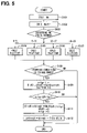
- FIG. 5 is a flow chart showing a calculating process of a learning value of each cylinder
- FIG. 6 is a flow chart showing a fuel injection control process
- FIG. 7 is a time chart showing a transition of a value corresponding to a current torque with a combustion in a specific cylinder
- FIG. 8 is a flowchart showing a fuel injection start timing estimating process
- FIG. 9 is a flowchart showing a calculation process of the combustion workload of each cylinder.
- FIGS. 10A-10E are time charts showing a rotation speed, a combustion torque, an inertia torque, a load torque, and a value corresponding to a current torque;
- FIG. 11 is a flowchart showing a process for correcting a dispersion in fuel injection amount between cylinders
- FIG. 12 is a block chart showing a control block for correcting a dispersion between cylinders
- FIG. 13 is a chart showing a waveform of a current rotation speed of each cylinder
- FIG. 14 is a graph showing a dispersion in fuel injection amount between cylinders
- FIG. 15 is a data map having coordinate axes of an engine rotation speed and a fuel injection amount
- FIG. 16 is a data map having coordinate axes of a common rail pressure and a fuel injection amount.
- FIG. 1 is a schematic view of a common rail fuel injection system.
- a multi-cylinder diesel engine 10 is provided with an electromagnetic fuel injector 11 for each cylinder, which communicates with a common rail 12 .
- a high-pressure pump 13 supplies high-pressure fuel to the common rail 12 .
- the common rail 12 accumulates high-pressure fuel of which pressure corresponds to injection pressure.
- the engine 10 drives the high-pressure pump 13 .
- the high-pressure pump 13 is provided with a suction control valve 13 a .
- a feed pump 14 pumps up fuel in a fuel tank 15 .
- the suction control valve 13 a is electromagnetically driven to adjust an amount of the fuel that is supplied to the high-pressure pump 13 .
- the common rail 12 is provided with a common rail pressure sensor 16 which detects fuel pressure in the common rail 12 .
- the common rail 12 is also provided with a relief valve (not shown) which relieves an excess pressure in the common rail 12 .
- a speed sensor 18 is provided at a vicinity of a crankshaft 17 of the engine 10 in order to detect a rotation speed of the crankshaft 17 .
- the speed sensosr 18 is, for example, an electromagnetic pick-up senor which generates pulse signals (NE pulse) representative of the rotation speed of the crank shaft 17 .
- NE pulse pulse signals
- an angle interval of the NE pulse is 30° CA so that the rotation speed can be detected every 30° CA.
- An ECU 20 includes a microcomputer which is comprised of CPU, ROM, RAM, EEPROM.
- the ECU 20 receives signals detected by the common rail pressure sensor 16 and the speed sensor 18 and other signals representative of an accelerator position and a vehicle speed.
- the ECU 20 determines a fuel injection quantity and fuel injection timing, and outputs a control signal to the injector 11 .
- FIG. 2A is a graph showing a crankshaft rotation speed behavior in detail.
- the combustion is conducted in a first cylinder (# 1 ), a third cylinder (# 3 ), a fourth cylinder (# 4 ), and a second cylinder (# 2 ) in this order.
- the fuel injection is performed every 180° CA.
- An increase and a decrease in the rotation speed are repeated in each stroke.
- the combustion in the cylinder increases the rotation speed, and then a load applied to the crankshaft decreases the rotation speed.
- a workload can be estimated with respect to each cylinder based on the rotation speed behavior.
- the workload of the subject cylinder can be calculated based on the rotation speed at the time when the combustion period of the cylinder is terminated. As shown in FIG. 2B , the workload of the first cylinder is calculated at a time of t 1 in which the combustion period terminates. The workload of the third cylinder is calculated at a time of t 2 .
- the detected signals (NE pulse) indicative of the rotation speed include noise and detection errors. Hence, the detected rotation speed indicated by a solid line deviates from the actual rotation speed indicated by a dashed line. The accurate workload cannot be calculated at the time of t 1 and t 2 .
- the rotation speed Ne is inputted into a filer M 1 to calculate a value corresponding to a current torque.
- This value corresponding to current torque is referred to as a current torque correspondent Neflt hereinafter.
- the filter M 1 calculates the current torque correspondent Neflt by extracting components of the rotation speed variation.
- the rotation speed Ne is detected in the output period of the NE pulse (30° CA).
- the filter M 1 is comprised of a band-pass filter (BPF) to eliminate high-frequency components and low-frequency components.
- BPF band-pass filter
- Neflt ( i ) k 1 *Ne ( i )+ k 2 *Ne ( i ⁇ 2)+ k 3* Neflt ( i ⁇ 1)+ k 4 *Neflt ( i ⁇ 2) (1)
- Ne(i) represents a present sampling value of the rotation speed
- Ne(i ⁇ 2) represent a sampling value of rotation speed at a time before previous time
- Neflt(i ⁇ 1) is a previous current torque correspondence
- Neflt(i ⁇ 2) is a current torque correspondence at a time before previous time
- k 1 to k 4 are constants. Every when the rotation speed Ne is inputted into the filter M 1 , the current torque correspondence Neflt (i) is calculated.
- Equation (1) is a discrete equation of a transfer function G(s) expressed by the following equation (2).
- ⁇ represents an attenuation coefficient
- ⁇ is a response frequency
- the response frequency ⁇ is defined by a combustion frequency of the engine 10 , and the constants k 1 -k 4 are determined based on the response frequency ⁇ .
- the combustion frequency is an angle frequency indicative of the number of combustion every unit angle. In a case of a four-cylinder engine, the combustion period (combustion angle period) is 180° CA, and the combustion frequency is an inverse of the combustion period.
- An integrating means M 2 shown in FIG. 3 integrates the current torque correspondent Neflt in a constant range every combustion period of each cylinder in order to obtain cylinder workloads Sneflt # 1 -Sneflt # 4 respectively.
- the NE pulses outputted every 30° CA are numbered with NE pulse numbers 0 - 23 .
- the NE pulse numbers 0 - 5 are given to the combustion period of the first cylinder
- the NE pulse numbers 6 - 11 are given to the combustion period of the third cylinder
- the NE pulse numbers 12 - 17 are given to the fourth cylinder
- the NE pulse numbers 18 - 23 are given to the second cylinder.
- the cylinder workloads Sneflt# 1 -Sneflt # 4 of the first to the fourth cylinder are respectively calculated based on the following equation (3).
- Sneflt ⁇ #1 ⁇ Neflt ⁇ ( 0 ) + Neflt ⁇ ( 1 ) + Neflt ⁇ ( 2 ) + ⁇ Neflt ⁇ ( 3 ) + Neflt ⁇ ( 4 ) + Neflt ⁇ ( 5 )
- Sneflt ⁇ #2
- the number of the cylinder will be expressed by #i, and the cylinder workloads Sneflt# 1 -Sneflt# 4 are expressed by Sneflt#i, hereinafter.
- FIG. 4 is a time chart showing the rotation speed Ne, the current torque correspondent Neflt, and the cylinder workloads Sneflt#i.
- the current torque correspondent Neflt periodically increases and decrease with respect to a reference reveal Ref.
- the cylinder workload Sneflt#i is obtained by integrating the current torque correspondent Neflt in the combustion period of each cylinder.
- the integrated value of the positive current torque correspondent Neflt corresponds to the combustion torque
- the integrated value of the negative current torque correspondent Neflt corresponds to the load torque.
- the reference level Ref is determined based on the average rotation speed between cylinders.
- the cylinder workload Sneflt#i has some variation. For example, in the first cylinder # 1 , the cylinder workload Sneflt# 1 is larger than zero, and in the second cylinder # 2 , the cylinder workload Sneflt# 2 is less than zero.
- the cylinder workload Sneflt#i shows differences of workloads between cylinders with respect to the theoretical value.
- FIG. 5 is a flowchart showing a calculating process of the learning value of each cylinder. This process is conducted by the ECU 20 when the NE pulse rises.
- step S 101 a time interval of NE pulse is calculated based on the present NE pulse timing and the previous NE pulse timing in order to calculate a present rotation speed Ne (current rotation speed).
- step S 102 the current torque correspondent Neflt(i) is calculated based on the above equation (1).
- step S 103 the present NE pulse number is determined.
- steps S 104 -S 107 the cylinder workload Snflt#i is calculated with respect to each cylinder # 1 -# 4 . That is, when the NE pulse number is 0 - 5 , the cylinder workload Sneflt# 1 of the first cylinder # 1 is calculated in step 104 . When the NE pulse number is 6 - 11 , the cylinder workload Sneflt# 3 of the third cylinder # 3 is calculated in step S 105 . When the NE pulse number is 12 - 17 , the cylinder workload Sneflt# 4 of the fourth cylinder # 4 is calculated in step S 106 . When the NE pulse number is 18 - 23 , the cylinder workload Sneflt# 2 of the second cylinder # 2 is calculated in step S 107 .
- step S 108 it is determined whether a learning condition of the cylinder workload is established.
- the learning condition is satisfied when the cylinder workloads of all cylinders have been calculated, a power transmission apparatus of a vehicle has been in a predetermined condition (a clutch is completely engaged), and an environmental condition has been predetermined situation (temperature of the engine coolant is higher than a predetermined temperature).
- step S 108 When the answer is NO in step S 108 , the procedure ends.
- step S 109 the number of integration times nitgr is incremented by 1, and a workload learning value Qlp#i is calculated based on a following equation (4).
- the cylinder workload Sneflt#i is made zero.
- Qlp#i Qlp#i+Ka*Sneflt#i (4)
- step S 110 it is determined whether the number of integration times nitgr has reached a predetermined number of times kitgr. When the number nitgr is lager than or equal to the number kitgr, the procedure proceeds to step S 111 .
- the workload learning value Qlp#i is averaged every integrating times to update the final learning value of workload Qlrn#i. By averaging the workload learning value Qlp#i, the error of the workload learning value Qlp#i can be canceled.
- step S 112 a differential learning value ⁇ Qlrn#i between cylinders is calculated based on the following equation (6).
- ⁇ Qlrn#i Qlrn#i ⁇ Qlrn#i/ 4 (6)
- a dispersion of the final learning value of workload Qlrn#i is calculated with respect to the average ( ⁇ Qlrn#i/4) of the final learning value of workload Qlrn#i.
- the final learning value of workload Qlrn#i and the differential learning value ⁇ Qlrn#i are stored in a memory, such as an EEPROM or a stand-by RAM. Multiple driving regions are defined based on the fuel injection amount and the rotation speed as parameters. The values Qlrn#i and AQlrn#i are stored every driving regions.
- step S 201 parameters indicative of the engine driving condition, such as rotation speed (an average rotation speed) or an accelerator position, are read.
- step S 202 a basic fuel injection amount is calculated based on the engine driving condition. The basic fuel injection amount may be corrected on the basis of the temperature of the engine coolant and a common rail pressure.
- step S 203 the learning value (the final learning value of workload Qlrn#i, or the differential learning value ⁇ Qlrn#i) is read with respect to the subject cylinder.
- step S 204 a command fuel injection amount (target fuel injection amount) is calculated by correcting the basic fuel injection amount.
- the fuel injection amount can be corrected by canceling an absolute characteristics error in each cylinder.
- a deviation between the target workload and the final learning value of workload Qlrn#i is calculated.
- the correction amount of the fuel injection amount is calculated based on the deviation to correct the basic fuel injection amount.
- the fuel injection amount can be corrected by canceling the dispersion of characteristics between cylinders.
- the correction amount of fuel injection is calculated based on the differential learning value ⁇ Qlrn#i with respect to every cylinders.
- the basic fuel injection amount is corrected based on the correction amount.
- step S 205 a fuel injection period is calculated based on the rotation speed and the command fuel injection amount.
- the fuel is injected into a combustion chamber (not shown) through the injector 11 during the fuel injection period.
- a fuel injection start timing, an ignition timing, a fuel injection terminating timing, and deviations (dispersions) of each timing can be estimated.
- FIG. 7 is a time chart showing the current torque correspondent of a specific cylinder.
- t 11 , t 12 , t 13 , and t 14 represent output timings of NE pulse.
- the current torque correspondent Neflt is calculated in these timings.
- the rotation speed increases.
- the time of t 11 is the output timing of No. 23 pulse
- the time of t 12 is the output timing of No. 0 pulse.
- the rotation speed decreases.
- the time of t 13 is the output timing of No. 5 pulse
- the timing of t 14 is the output timing of No. 6 pulse.
- a reference time instance Tc 0 is predetermined.
- the time instance Tc is compared with the reference time instance Tc 0 to calculate the deviation time ⁇ Tc of fuel injection starting timing and the ignition timing.
- ⁇ Tc K 1*( Tc ⁇ Tc 0) (8)
- the calculated fuel injection starting timing or the calculated ignition timing are compared with each other between respective cylinders.
- This difference between respective cylinders can be derived by calculating the average and obtaining a difference between the average and calculated value.
- a reference time instance Tf 0 is predetermined.
- the time instance Tf is compared with the reference time instance Tf 0 to calculate the deviation time ⁇ Tc of fuel injection stop timing.
- ⁇ Tf K 2*( Tf ⁇ Tf 0) (10)
- the calculated fuel injection stop timings are compared with each other between respective cylinders.
- This difference between respective cylinders can be derived by calculating the average and obtaining a difference between the average and calculated value.
- FIG. 8 is a flowchart showing a fuel injection start timing estimating process.
- step S 301 it is determined whether NE pulse number is a predetermined pulse number “n”. For example, in the first cylinder # 1 , “n” is 23.
- the present time instance is stored as Ta in step S 302 .
- step S 303 the present current torque correspondent Neflt is stored as Ya.
- step S 304 it is determined whether the NE pulse number is “n+1”. For example, in the first cylinder # 1 , “n” is 0. When the NE pulse number is “n+1”, the present time instance is stored as Tb in step S 305 . In step S 306 , the present current torque correspondent Neflt is stored as Yb.
- step S 307 the time instance Tc in which the current torque correspondent Neflt is the threshold Yc is calculated to estimate the fuel injection starting timing.
- step S 308 a deviation of the fuel injection starting timing is estimated based on the above equation (8).
- the command fuel injection period is corrected based on the estimated value.
- the ignition timing and the fuel injection stop timing are calculated according to the process shown in FIG. 8 by use of the equations (7)-(10).
- the current torque correspondent Neflt can be obtained appropriately based on the fuel injection condition and the combustion condition. Furthermore, the current torque correspondent Neflt is integrated within the specific range with respect to each cylinder so that the cylinder workload Sneflt#i is calculated.
- the fuel injection amount is adjusted cylinder-by-cylinder based on the cylinder workload Sneflt#i of each cylinder (actually, the final learning value of workload Qlrn#i, or the differential learning value ⁇ Qlrn#i), so that the characteristics of each cylinder can be desirably controlled. Hence, the emission is restricted and the drivability is enhanced.
- the absolute dispersion of characteristics of each cylinder can be detected as well as the relative dispersion between cylinders, so that various controls can be performed cylinder by cylinder.
- the band-pass filter (BPF) is utilized as a filtering means, the varying components of low frequency due to acceleration or deceleration and the varying components of high frequency of noise can be eliminated from the rotation speed signal in order to extract only torque varying components. Thereby, the current torque correspondent Neflt can be accurately calculated to reduce the dispersion of characteristics between cylinders.
- the fuel injection timing, the ignition timing, and the fuel injection stop timing can be estimated based on the current torque correspondent Neflt, the dispersion of fuel injection timing, the ignition timing, and the fuel injection stop timing can be restricted.
- the command fuel injection amount is calculated by correcting the fuel injection amount based on the learning values.
- the command furl injection period can be corrected based on the learning values.
- the cylinder workload Sneflt#i is calculated by integrating the current torque correspondent Neflt in a combustion period.
- the workload due to the combustion and the workload due to the load can be respectively calculated.
- the current torque correspondent Neflt is integrated in a specific range in which the rotation speed increases in order to obtain the workload due to the combustion.
- the current torque correspondent Neflt is integrated in a specific range in which the rotation speed decreases in order to obtain the workload due to the load.
- the fuel injection amount is controlled based on each workload.
- the current torque correspondent Neflt varies according to the stroke of the piston and a rotational angle position of the crankshaft. This variation depends on the combustion torque, an inertia torque, and the load torque.
- FIG. 10A-10E respectively show the rotation speed, the combustion torque, the inertia torque, the load torque, and the current torque correspondent.
- an area denoted by “D 1 ” corresponds to the workload due to the combustion
- an area denoted by “D 2 ” corresponds to the workload due to the load.
- the cylinder workload Sneflt#i is calculated at the time when combustion is occurred and at the time when the combustion is not occurred. A difference between these cylinder workloads is calculated to obtain the workload due to combustion. When the combustion is not occurred, the fuel injection is not conducted, so that the cylinder workload Sneflt#i does not includes the workload corresponding to the combustion torque.
- the current torque correspondent Neflt is a sum of the combustion torque, the inertia torque, and the load torque.
- the current torque correspondent Neflt is a sum of the inertia torque and the load torque. That is, the current torque correspondent is different between the combustion period and the non-combustion period.
- step S 401 it is determined whether it is a fuel-cut period.
- the procedure proceeds to step S 402 in which the cylinder workload Sneflt#i at the time of combustion is calculated.
- the procedure proceeds to step S 403 in which the cylinder workload Sneflt#i at the time of non-combustion is calculated.
- step S 404 it is determined whether the cylinder workload Sneflt#i has been calculated at both situations.
- step S 405 the procedure proceeds to step S 405 in which the cylinder workload Sneflt#i is calculated by subtracting the cylinder workload at the fuel-cut period from the cylinder workload at the combustion period.
- the combustion torque of each cylinder can be calculated based on a difference between the current torque correspondent Neflt which is obtained during combustion period and the current torque correspondent Neflt which is obtained during non-combustion period.
- the differential combustion torque between cylinders can be calculated by comparing the combustion torque of each cylinder.
- the rotation speed Ne starts to increase at the time of “A 1 ”, “A 2 ”, and “A 3 ” in a cylinder.
- An angle between “A 1 ” and “A 2 ” and an angle between “A 2 ” and “A 3 ” correspond to combustion angle periods.
- the combustion torque starts to increase at a time of stating of combustion, and starts to decrease at a time of terminating of combustion.
- the inertia torque varies according to a rotational inertia torque of a flywheel (not shown).
- FIG. 10C when the rotation speed increases, the inertia torque generally becomes negative values, and when the rotation speed decreases, the inertial torque generally becomes positive values.
- the load torque is always negative value and varies in a small range. The sum of the combustion torque, the inertia torque, and the load torque corresponds to the current torque correspondent.
- each cylinder has different current torque correspondent Neflt.
- the current torque correspondent Neflt (C 1 , C 2 ) corresponds to the characteristics of each cylinder. Peak values and bottom values of the current torque correspondent Neflt are different between cylinders.
- the current torque correspondent Neflt is calculated at the same rotational angle position with respect to each cylinder, and then the characteristics of each cylinder can be estimated based on the current torque correspondent. Alternatively, the difference in characteristics between the cylinders can be estimated by comparing the current torque correspondent Neflt between the cylinders. In a structure that the NE pulse has the pulse number, the current torque correspondent Neflt can be calculated with respect to the NE pulse having the same pulse number. Multiple rotational angle positions are provided to calculate the current torque correspondent Neflt. These multiple angle positions are substantially equal to each other.
- the peak value or the bottom value of the current torque correspondent Neflt is obtained to estimate the characteristics of each cylinder.
- the difference in characteristics between cylinders can be estimated by comparing at least one of the peak value and the bottom value between cylinders.
- the characteristics of each cylinder can be evaluated based on the peak value of the current torque correspondent, the bottom value of the current torque correspondent, or the difference between the peak value and the bottom value.
- a low-pass filter (LPF) or a high-pass-filter (HPF) can be used instead of the band-pass filter (BPF).
- the combustion frequency is a response frequency co of the transfer function which defines the LPH or the HPF, whereby the current torque correspondent can be calculated.
- a resolver can be used to detect the rotational position of the crankshaft linearly.
- the current torque correspondent Neflt can be calculated at arbitrary timing.
- the current torque correspondent Neflt is continuously calculated to estimate the fuel injection start timing, the ignition timing, or fuel injection stop timing.
- the time instance is measured.
- the fuel injection start timing, the ignition timing, or the fuel injection stop timing can be directly estimated from the measured time instance.
- FIG. 11 is a flowchart showing a process for correcting a dispersion in fuel injection amount between cylinders.
- step S 10 a current rotation speed shown in FIG. 13 is measured. Specifically, the current rotation speed is derived from a pulse interval between a first rotational angle (ATDC 42°) and a second rotational angel (ATDC 72°).
- step S 20 it is determined whether the present value and the previous value are in the same region. For example, as shown in FIG.
- step S 6 it is determined whether the present measured data (the current rotation speed) and the previous measured data are in the same region with respect to multiple regions which are defined in data map “A” having coordinate axes of the rotation speed and the fuel injection amount.
- the procedure proceeds to step S 30 .
- the procedure goes back to step S 10 .
- a data map “B” having coordinate axes of the common rail pressure and the fuel injection amount.
- the data map “B” is shown in FIG. 16 .
- step S 10 The measured data in step S 10 is inputted into a low-pass filter M 10 shown in FIG. 12 to extract low-frequency components.
- step S 40 the extracted data is stored in the corresponding region defined by the data map “A” or data map “B”. The stored data of each cylinder is integrated respectively. In this embodiment, since the diesel engine has four cylinders, four integrated data are generated by low-pass filter M 10 .
- step S 50 it is determined whether the number of data stored in the specific region has reached a predetermined number. When the answer is YES in step S 50 , the procedure proceeds to step S 60 . When the answer is No, the procedure goes back to step S 10 .
- step S 60 the data is averaged by an averaging means M 20 shown in FIG. 12 , whereby the dispersion in fuel injection amount cylinders is extracted as shown in FIG. 14 .
- FIG. 14 shows dispersion in fuel injection amount due to the individual difference between injectors. The magnitude of the dispersion dQ in the fuel injection amount is expressed by a numeral “0” to “5”. The dispersion of the speed between cylinders # 1 to # 4 is illustrated in FIG. 14 . With respect to cylinders # 1 , and # 4 , the dispersion dQ in fuel injection amount is the positive value. With respect to cylinders # 3 , and # 2 , the dispersion dQ is the negative value.
- FIG. 14 shows dispersion in fuel injection amount due to the individual difference between injectors.
- the magnitude of the dispersion dQ in the fuel injection amount is expressed by a numeral “0” to “5”.
- the dispersion of the speed between cylinders # 1 to # 4 is illustrated
- the filter output 14 shows the averaged value of the filter output with respect to the crank angel.
- the filter output is added by the amount of 2 mm 3 /stroke relative to the averaged amount with respect to the cylinders # 1 , and # 4 in order to average the filtered output.
- the filter output is subtracted by the amount of 2 mm 3 /stroke relative to the averaged amount with respect to the cylinders # 3 , and # 2 in order to average the filtered output.
- the data is obtained between the first rotational angel (ATDC 42°) and the second rotational angel (ATDC 72°).
- the averaged process value of the filter output between the first rotational angel and the second rotational angel shown in FIG. 14 is obtained in step S 60 .
- step S 60 The averaging process in step S 60 is described in detail hereinafter.
- the integrated data obtained in step S 40 is divided by the predetermined value to calculate the average of the integrated data with respect to each cylinder.
- Four averages are obtained. These four averages are integrated and divided by the number of cylinder (four, in this embodiment) to calculate the whole average.
- the deviation of each cylinder is calculated by subtracting the individual average of each cylinder from the whole average of every cylinder. This deviation is converted into a value to the fuel injection amount to calculate the fuel injection correction amount “q”.
- step S 70 the fuel injection amount is corrected in such a manner as to reduce the dispersion in fuel injection amount between the cylinders.
- the corrected command fuel injection amount Qf is calculated by adding the correction amount “q” on the command fuel injection amount Q.
- the fuel injector 11 is controlled based on the corrected command fuel injection amount Qf.
- the current rotation speed of each cylinder is filtered by low-pass filter M 10 to obtain the low-frequency components, so that the high-frequency noise is eliminated to accurately detect the rotational variation between cylinders.
- the predetermined piece of data is integrated and is averaged, so that only the dispersion of the fuel injection between the cylinders can be detected.
- the fuel injection amount is corrected in such a manner as to reduce the dispersion between cylinders, so that the dispersion in the rotation speed between cylinders can be restricted.
- the above-described control can be applied to whole driving rage of engine.
- the dispersion of the rotation speed between cylinders can be corrected even when the engine is running in a normal speed as well as idling speed in order to reduce the emission and enhance the drivability.
- the data filtered by the low-pass filter M 10 is stored in the data map “A” or the data map “B”, and the predetermined piece of data is integrated and averaged in every region. Thereby, the fuel injection correction amount can be derived every regions whish are defined in the data map “A” or “B”.
- the fuel injection correction amount learned in the low-load and low-speed region is not used in the high-load and high-speed region, so that the appropriate correction can be performed in a whole driving range of the engine.
- the present embodiment can be applied to a gasoline engine as well as the diesel engine.
Landscapes
- Engineering & Computer Science (AREA)
- Chemical & Material Sciences (AREA)
- Combustion & Propulsion (AREA)
- Mechanical Engineering (AREA)
- General Engineering & Computer Science (AREA)
- Combined Controls Of Internal Combustion Engines (AREA)
- Electrical Control Of Air Or Fuel Supplied To Internal-Combustion Engine (AREA)
Abstract
Description
Neflt(i)=k1*Ne(i)+k2*Ne(i−2)+k3*Neflt(i−1)+k4*Neflt (i−2) (1)
Qlp#i=Qlp#i+Ka*Sneflt#i (4)
Qlrn#i=Qlrn#i+Kb*Qlp#i/kitgr (5)
ΔQlrn#i=Qlrn#i−ΣQlrn#i/4 (6)
Tc=(Tb−Ta)*(Yc−Ya)/(Yb−Ya)+Ta (7)
ΔTc=K1*(Tc−Tc0) (8)
Tf=(Te−Td)*(Yf−Yd)/(Ye−Yd)+Td (9)
ΔTf=K2*(Tf−Tf0) (10)
Claims (23)
Applications Claiming Priority (6)
| Application Number | Priority Date | Filing Date | Title |
|---|---|---|---|
| JP2005-182117 | 2005-06-22 | ||
| JP2005182117 | 2005-06-22 | ||
| JP2005221476A JP4400526B2 (en) | 2005-07-29 | 2005-07-29 | Control device for internal combustion engine |
| JP2005-221476 | 2005-07-29 | ||
| JP2006133801A JP2007032557A (en) | 2005-06-22 | 2006-05-12 | Fuel injection control device |
| JP2006-133801 | 2006-05-12 |
Publications (2)
| Publication Number | Publication Date |
|---|---|
| US20060293828A1 US20060293828A1 (en) | 2006-12-28 |
| US7317983B2 true US7317983B2 (en) | 2008-01-08 |
Family
ID=36763779
Family Applications (1)
| Application Number | Title | Priority Date | Filing Date |
|---|---|---|---|
| US11/455,702 Active 2026-07-08 US7317983B2 (en) | 2005-06-22 | 2006-06-20 | Fuel injection controlling apparatus for internal combustion engine |
Country Status (4)
| Country | Link |
|---|---|
| US (1) | US7317983B2 (en) |
| EP (1) | EP1736659B1 (en) |
| KR (1) | KR100791163B1 (en) |
| ES (1) | ES2621134T3 (en) |
Cited By (10)
| Publication number | Priority date | Publication date | Assignee | Title |
|---|---|---|---|---|
| US20070250249A1 (en) * | 2006-04-24 | 2007-10-25 | Honda Motor Co., Ltd. | Workload calculation apparatus and method for internal combustion engine, and engine control unit |
| US20080009999A1 (en) * | 2006-06-06 | 2008-01-10 | Denso Corporation | Fuel injection controller |
| US20080114525A1 (en) * | 2006-11-10 | 2008-05-15 | Hitoki Sugimoto | Internal combustion engine apparatus, vehicle and control method of internal combustion engine apparatus |
| US20080120013A1 (en) * | 2006-11-17 | 2008-05-22 | Honda Motor Co., Ltd. | Control system for internal combustion engine |
| US20080319637A1 (en) * | 2007-06-20 | 2008-12-25 | Denso Corporation | Injection quantity control unit and fuel injection system having the unit |
| US20090112444A1 (en) * | 2007-10-24 | 2009-04-30 | Denso Corporation | Control device and control system of internal combustion engine |
| US20100116247A1 (en) * | 2007-05-18 | 2010-05-13 | Honda Motor Co., Ltd. | Control system for internal combustion engine |
| US20110185798A1 (en) * | 2010-11-19 | 2011-08-04 | Ford Global Technologies, Llc | Method for diagnosing fuel injectors |
| US20130160536A1 (en) * | 2011-12-26 | 2013-06-27 | Denso Corporation | Abnormality diagnosis apparatus for engine control system |
| US20140156168A1 (en) * | 2011-06-10 | 2014-06-05 | Mtu Friedrichshafen Gmbh | Method for controlling rail pressure |
Families Citing this family (11)
| Publication number | Priority date | Publication date | Assignee | Title |
|---|---|---|---|---|
| JP4353220B2 (en) * | 2006-08-29 | 2009-10-28 | 株式会社デンソー | Fuel injection control device for internal combustion engine |
| JP4861921B2 (en) * | 2007-07-26 | 2012-01-25 | ヤンマー株式会社 | Engine with fuel injection correction function |
| DE102007037037B3 (en) | 2007-08-06 | 2009-02-12 | Mtu Friedrichshafen Gmbh | Method for controlling an internal combustion engine |
| JP4442670B2 (en) * | 2007-09-19 | 2010-03-31 | 株式会社デンソー | Fuel injection control device for internal combustion engine |
| WO2010013773A1 (en) * | 2008-07-31 | 2010-02-04 | 株式会社フチノ | Device and method for measuring engine torque, and control program |
| JP2010275989A (en) * | 2009-06-01 | 2010-12-09 | Denso Corp | Fuel injection control device for internal combustion engine |
| JP5103459B2 (en) * | 2009-10-30 | 2012-12-19 | 日立オートモティブシステムズ株式会社 | Engine control device |
| JP5168336B2 (en) | 2010-10-05 | 2013-03-21 | 株式会社デンソー | Control device for internal combustion engine |
| DE102019219541B4 (en) * | 2019-12-13 | 2021-08-05 | Vitesco Technologies GmbH | Method and engine control for multiple injection with quantity correction for an internal combustion engine |
| JP7425923B2 (en) * | 2021-03-10 | 2024-01-31 | 日立Astemo株式会社 | Electronic control device and combustion state detection system |
| JP7101841B1 (en) * | 2021-04-16 | 2022-07-15 | 三菱電機株式会社 | Internal combustion engine control device and control method |
Citations (5)
| Publication number | Priority date | Publication date | Assignee | Title |
|---|---|---|---|---|
| US4715339A (en) * | 1984-09-01 | 1987-12-29 | Kawasaki Jukogyo Kabushiki Kaisha | Governor for internal combustion engine |
| JPH0650077A (en) | 1992-07-24 | 1994-02-22 | Maeda Seikan Kk | Earth-moving device of earth auger |
| DE19527218A1 (en) | 1994-12-23 | 1996-06-27 | Bosch Gmbh Robert | Running control for automobile i.c. engine |
| JPH08218924A (en) | 1994-12-23 | 1996-08-27 | Robert Bosch Gmbh | Method and apparatus for controlling internal combustion engine to stable operation |
| US6678605B2 (en) * | 2001-05-25 | 2004-01-13 | Mazda Motor Corporation | Control system for internal combustion engine |
Family Cites Families (6)
| Publication number | Priority date | Publication date | Assignee | Title |
|---|---|---|---|---|
| US4532592A (en) * | 1982-12-22 | 1985-07-30 | Purdue Research Foundation | Engine-performance monitor and control system |
| US4697561A (en) * | 1985-04-15 | 1987-10-06 | Purdue Research Foundation | On-line engine torque and torque fluctuation measurement for engine control utilizing crankshaft speed fluctuations |
| JPS62197657A (en) | 1986-02-26 | 1987-09-01 | Hitachi Ltd | Control device of internal combustion engine |
| JP2793729B2 (en) * | 1991-10-09 | 1998-09-03 | 株式会社日立製作所 | Engine fuel injection amount control device |
| JP3393626B2 (en) * | 1994-09-19 | 2003-04-07 | 株式会社日立ユニシアオートモティブ | Ignition timing control device for internal combustion engine |
| DE19633066C2 (en) * | 1996-08-16 | 1998-09-03 | Telefunken Microelectron | Method for the cylinder-selective control of a self-igniting internal combustion engine |
-
2006
- 2006-06-20 US US11/455,702 patent/US7317983B2/en active Active
- 2006-06-21 ES ES06115820.0T patent/ES2621134T3/en active Active
- 2006-06-21 EP EP06115820.0A patent/EP1736659B1/en not_active Not-in-force
- 2006-06-21 KR KR1020060055897A patent/KR100791163B1/en not_active Expired - Fee Related
Patent Citations (5)
| Publication number | Priority date | Publication date | Assignee | Title |
|---|---|---|---|---|
| US4715339A (en) * | 1984-09-01 | 1987-12-29 | Kawasaki Jukogyo Kabushiki Kaisha | Governor for internal combustion engine |
| JPH0650077A (en) | 1992-07-24 | 1994-02-22 | Maeda Seikan Kk | Earth-moving device of earth auger |
| DE19527218A1 (en) | 1994-12-23 | 1996-06-27 | Bosch Gmbh Robert | Running control for automobile i.c. engine |
| JPH08218924A (en) | 1994-12-23 | 1996-08-27 | Robert Bosch Gmbh | Method and apparatus for controlling internal combustion engine to stable operation |
| US6678605B2 (en) * | 2001-05-25 | 2004-01-13 | Mazda Motor Corporation | Control system for internal combustion engine |
Non-Patent Citations (2)
| Title |
|---|
| Korean Examination Report issued Jul. 26, 2007 in Application No. 10-2006-0055897 with English translation. |
| Korean Office Action issued Mar. 28, 2007, and an English translation, issued in corresponding Korean Application No. 10-2006-0055897. |
Cited By (23)
| Publication number | Priority date | Publication date | Assignee | Title |
|---|---|---|---|---|
| US7467041B2 (en) * | 2006-04-24 | 2008-12-16 | Honda Motor Co., Ltd. | Workload calculation apparatus and method for internal combustion engine, and engine control unit |
| US20070250249A1 (en) * | 2006-04-24 | 2007-10-25 | Honda Motor Co., Ltd. | Workload calculation apparatus and method for internal combustion engine, and engine control unit |
| US20080009999A1 (en) * | 2006-06-06 | 2008-01-10 | Denso Corporation | Fuel injection controller |
| US7474952B2 (en) * | 2006-06-06 | 2009-01-06 | Denso Corporation | Fuel injection controller |
| US20080114525A1 (en) * | 2006-11-10 | 2008-05-15 | Hitoki Sugimoto | Internal combustion engine apparatus, vehicle and control method of internal combustion engine apparatus |
| US7845333B2 (en) * | 2006-11-10 | 2010-12-07 | Toyota Jidosha Kabushiki Kaisha | Internal combustion engine apparatus, vehicle and control method of internal combustion engine apparatus |
| US20080120013A1 (en) * | 2006-11-17 | 2008-05-22 | Honda Motor Co., Ltd. | Control system for internal combustion engine |
| US7480557B2 (en) * | 2006-11-17 | 2009-01-20 | Honda Motor Co., Ltd. | Control system for internal combustion engine |
| US20100116247A1 (en) * | 2007-05-18 | 2010-05-13 | Honda Motor Co., Ltd. | Control system for internal combustion engine |
| US8272367B2 (en) * | 2007-05-18 | 2012-09-25 | Honda Motor Co., Ltd. | Control system for internal combustion engine |
| US20080319637A1 (en) * | 2007-06-20 | 2008-12-25 | Denso Corporation | Injection quantity control unit and fuel injection system having the unit |
| US7599783B2 (en) | 2007-06-20 | 2009-10-06 | Denso Corporation | Injection quantity control unit and fuel injection system having the unit |
| US8150600B2 (en) | 2007-10-24 | 2012-04-03 | Denso Corporation | Control device and control system of internal combustion engine |
| US20090112444A1 (en) * | 2007-10-24 | 2009-04-30 | Denso Corporation | Control device and control system of internal combustion engine |
| US20110185798A1 (en) * | 2010-11-19 | 2011-08-04 | Ford Global Technologies, Llc | Method for diagnosing fuel injectors |
| US8051704B2 (en) | 2010-11-19 | 2011-11-08 | Ford Global Technologies, Llc | Method for diagnosing fuel injectors |
| DE102011086531A1 (en) | 2010-11-19 | 2012-05-24 | Ford Global Technologies, Llc | Method for diagnosing fuel injectors |
| US8459105B2 (en) | 2010-11-19 | 2013-06-11 | Ford Global Technologies, Llc | Method for diagnosing fuel injectors |
| DE102011086531B4 (en) | 2010-11-19 | 2023-09-21 | Ford Global Technologies, Llc | Method for diagnosing fuel injectors |
| US20140156168A1 (en) * | 2011-06-10 | 2014-06-05 | Mtu Friedrichshafen Gmbh | Method for controlling rail pressure |
| US9657669B2 (en) * | 2011-06-10 | 2017-05-23 | Mtu Friedrichshafen Gmbh | Method for controlling rail pressure |
| US20130160536A1 (en) * | 2011-12-26 | 2013-06-27 | Denso Corporation | Abnormality diagnosis apparatus for engine control system |
| US8756984B2 (en) * | 2011-12-26 | 2014-06-24 | Denso Corporation | Abnormality diagnosis apparatus for engine control system |
Also Published As
| Publication number | Publication date |
|---|---|
| US20060293828A1 (en) | 2006-12-28 |
| EP1736659A2 (en) | 2006-12-27 |
| KR20060134828A (en) | 2006-12-28 |
| ES2621134T3 (en) | 2017-07-03 |
| EP1736659A3 (en) | 2011-11-30 |
| EP1736659B1 (en) | 2017-01-11 |
| KR100791163B1 (en) | 2008-01-02 |
Similar Documents
| Publication | Publication Date | Title |
|---|---|---|
| US7317983B2 (en) | Fuel injection controlling apparatus for internal combustion engine | |
| JP4678397B2 (en) | Fuel injection state detection device | |
| US7647160B2 (en) | Fuel injection system with injection quantity learning function | |
| EP1491751B1 (en) | Injection quantity control device of diesel engine | |
| JP4428427B2 (en) | Fuel injection characteristic detecting device and fuel injection command correcting device | |
| US7474952B2 (en) | Fuel injection controller | |
| EP0651150A2 (en) | Fuel injection apparatus for engine | |
| EP1363006A1 (en) | Method of calculating engine torque | |
| JPH09256897A (en) | Fuel injection control device for internal combustion engine | |
| US8977471B2 (en) | Controller for internal combustion engine | |
| JP2005307747A (en) | Fuel supply device for internal combustion engine | |
| US7725242B2 (en) | Controller of internal combustion engine | |
| US7343240B2 (en) | Fuel injection controller | |
| US6102000A (en) | Fuel injection apparatus for engine | |
| JP5482532B2 (en) | Fuel injection control device | |
| US20030131823A1 (en) | Fuel injection system | |
| CN100432406C (en) | Fuel injection control apparatus for internal combustion engine | |
| JP4893851B2 (en) | Fuel injection state detection device | |
| JP4400526B2 (en) | Control device for internal combustion engine | |
| JP4424380B2 (en) | Injection amount control device and fuel injection system using the same | |
| JP4513895B2 (en) | Fuel injection system control device | |
| EP2037104B1 (en) | Fuel volatility recognition method during the postcranking step of an internal combustion engine | |
| JP2005163559A (en) | Accumulated fuel injection system | |
| JP2002089344A (en) | Time change determination device for fuel injection device | |
| JP4610407B2 (en) | Fuel injection device for internal combustion engine |
Legal Events
| Date | Code | Title | Description |
|---|---|---|---|
| AS | Assignment |
Owner name: DENSO CORPORATION, JAPAN Free format text: ASSIGNMENT OF ASSIGNORS INTEREST;ASSIGNORS:ISHIZUKA, KOJI;NAKATA, KENICHIRO;KAWAMURA, JUN;REEL/FRAME:017997/0528 Effective date: 20060605 |
|
| STCF | Information on status: patent grant |
Free format text: PATENTED CASE |
|
| FPAY | Fee payment |
Year of fee payment: 4 |
|
| FPAY | Fee payment |
Year of fee payment: 8 |
|
| MAFP | Maintenance fee payment |
Free format text: PAYMENT OF MAINTENANCE FEE, 12TH YEAR, LARGE ENTITY (ORIGINAL EVENT CODE: M1553); ENTITY STATUS OF PATENT OWNER: LARGE ENTITY Year of fee payment: 12 |