US7299769B2 - Condensing gas fired water heater - Google Patents
Condensing gas fired water heater Download PDFInfo
- Publication number
- US7299769B2 US7299769B2 US11/323,436 US32343605A US7299769B2 US 7299769 B2 US7299769 B2 US 7299769B2 US 32343605 A US32343605 A US 32343605A US 7299769 B2 US7299769 B2 US 7299769B2
- Authority
- US
- United States
- Prior art keywords
- tank
- water heater
- combustion chamber
- flue
- closed
- Prior art date
- Legal status (The legal status is an assumption and is not a legal conclusion. Google has not performed a legal analysis and makes no representation as to the accuracy of the status listed.)
- Expired - Fee Related, expires
Links
Images


Classifications
-
- F—MECHANICAL ENGINEERING; LIGHTING; HEATING; WEAPONS; BLASTING
- F24—HEATING; RANGES; VENTILATING
- F24H—FLUID HEATERS, e.g. WATER OR AIR HEATERS, HAVING HEAT-GENERATING MEANS, e.g. HEAT PUMPS, IN GENERAL
- F24H1/00—Water heaters, e.g. boilers, continuous-flow heaters or water-storage heaters
- F24H1/18—Water-storage heaters
- F24H1/20—Water-storage heaters with immersed heating elements, e.g. electric elements or furnace tubes
- F24H1/205—Water-storage heaters with immersed heating elements, e.g. electric elements or furnace tubes with furnace tubes
- F24H1/206—Water-storage heaters with immersed heating elements, e.g. electric elements or furnace tubes with furnace tubes with submerged combustion chamber
-
- F—MECHANICAL ENGINEERING; LIGHTING; HEATING; WEAPONS; BLASTING
- F24—HEATING; RANGES; VENTILATING
- F24H—FLUID HEATERS, e.g. WATER OR AIR HEATERS, HAVING HEAT-GENERATING MEANS, e.g. HEAT PUMPS, IN GENERAL
- F24H9/00—Details
- F24H9/18—Arrangement or mounting of grates or heating means
- F24H9/1809—Arrangement or mounting of grates or heating means for water heaters
- F24H9/1832—Arrangement or mounting of combustion heating means, e.g. grates or burners
- F24H9/1836—Arrangement or mounting of combustion heating means, e.g. grates or burners using fluid fuel
Definitions
- the present invention relates generally to a fire tube water heater/heating boiler having a pressurized, submerged combustion chamber and curved, submerged fire tubes, the flue products produced within the fire tubes being cooled below their dew point, causing water vapor normally entrained in combustion gases to condense to a liquid on the heating surfaces of the fire tubes.
- Typical prior art gas/oil fired water heaters featured non-pressurized external combustion chambers.
- the location of the combustion chamber on the exterior of the water heater resulted in lost heat and lower combustion efficiency.
- the tubes and support plates were not easily accessible and required disassembly of the entire tank for maintenance and replacement.
- the gas fired water heater of the invention includes a normally closed tank containing water under pressure, the tank having a top wall, depending cylindrical sidewalls and a bottom opening, a water inlet and a water outlet.
- a combustion chamber assembly having a submerged, pressurized combustion chamber with multiple external heating surfaces extends through the bottom opening of the closed tank so that all of the heating surfaces are submerged in the water under pressure.
- a a forced draft burner assembly is mounted on the bottom opening of the closed tank and communicates with the combustion chamber for causing combustion to take place within the submerged, pressurized combustion chamber.
- a rotomolded jacket encloses the normally closed tank.
- a support stand has upwardly extending legs located on either of two sides of the closed and jacketed tank, the support stand being attached to the closed tank at a pivot point, whereby the tank is rotatable about the pivot point between a vertical position and a horizontal position.
- the preferred combustion chamber comprises a substantially cylindrical body portion having an open end located adjacent the closed tank bottom opening and an opposite closed end.
- the multiple external heating surfaces preferably comprise a plurality curved fire tubes, the fires tubes each having a short leg joined to the closed end of the combustion chamber and a long leg which curves downwardly and exits the closed tank adjacent the bottom opening thereof.
- a flue collector is mounted on the exterior of the closed tank adjacent the bottom opening thereof, the flue collector having an annular chamber surrounding the exterior mounted blower and separated therefrom.
- the annular chamber communicates with each long leg of each of the fire tubes for collecting flue gases and condensate formed therein.
- the flue collector is preferably formed as a seamless lower portion with upturned walls so as to facilitate a leak free area without seams where an acidic condensate might collect.
- the water inlet of the closed tank is located on the tank sidewalls at a point proximate the exit point of the long legs of the curved fire tubes from the closed tank into the flue collector to facilitate heat transfer.
- At least selected ones of the curved fire tubes are provided with baffles to increase flue velocity and increase impingement of flue gases on an inner wall surface of the fire tubes.
- the fire tube interiors are divided into a condensing region and a non-condensing region and non-metallic plastic baffles may be located in the condensing region of the fire tube interiors.
- the baffles are corkscrew in shape and may have cylindrical plastic rods placed in a condensing region of the fire tube interiors.
- the preferred normally closed water storage tank is provided with a bottom mounting flange.
- a circular, flat metal sheet is used as a lower closure for the normally closed tank as well as for mounting the forced draft burner assembly, the flat metal sheet being gasketed and bolted to the bottom mounting flange of the tank.
- the burner may be equipped with a variable orifice arrangement for controlling the intake of combustion air to the combustion chamber.
- An electrical control panel is mounted on the rotomolded jacket by means of a floating mounting stud on the closed tank exterior cylindrical sidewalls in cooperation with a positive attachment to a flange surface molded into the rotomolded plastic jacket.
- the control panel can be equipped with a special hinged door arrangement which provides a positive attachment mechanism for mounting the door on the panel.
- FIG. 1 is a front perspective view of the water heater of the invention.
- FIG. 2 is a side view of the water heater of FIG. 1 .
- FIG. 3 is a front view of the upper portion of the rotomolded jacket of the water heater of FIG. 1 showing the electrical control panel located thereon.
- FIG. 4 is a side view of the water heater of FIG. 3 illustrating the installation of the control panel in exploded fashion.
- FIG. 5 is a side view of one version of the isolated control panel showing the attachment of the hinged door panels.
- FIG. 6 is a front view of the front panel components of the control panel of FIG. 5 .
- FIG. 7 is a side view of the water heater of FIG. 1 showing the support stand which allows the water heater to be rotated ninety degrees about its normally vertical axis for transport, maintenance or repair operations.
- FIG. 8 is a partial, cross sectional view of the assembled water heater of FIG. 1 also showing certain of the internal components thereof.
- FIG. 9 is a view similar to FIG. 6 , but with the burner and blower assemblies being shown in exploded fashion.
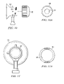
- FIG. 10 is a side view of the rear portion of the burner of the water heater of the invention showing the burner air intake orifice fitted with a plastic orifice cap.
- FIG. 10A is an end view of the plastic orifice cap of FIG. 10 .
- FIG. 11 is an alternative burner construction showing the burner orifice opening thereof.
- FIG. 11A is an end view of the steel orifice ring which is used with the burner orifice of FIG. 11 .
- FIG. 12 is an isolated view of the burner and blower assembly showing the assembly of the flue collector thereon.
- FIG. 13 is an isolated, side view of the flue collector of FIG. 12 .
- FIG. 14 is a detail view of the sidewall construction of the flue collector of FIG. 13 .
- FIG. 15 is a top view of the flue collector of FIG. 13 .
- FIG. 1 shows the water heater of the present invention designated generally as 11 .
- the term “water heater”, as used in this discussion, will be understood to encompass a heating boiler, depending upon the sizing and capacities of the various components to be described.
- the water heater 11 includes a rotomolded outer jacket 8 formed from a synthetic, non-conductive material and a support stand 10 for supporting the water heater in a normal vertical operating position.
- the jacket is provided as a one-piece upper section 12 and a two-piece “clam shell” lower enclosure 14 .
- the rotomolded outer jacket could also be comprised of several large connectible vertical segments that can be connected together to form various diameter outer enclosures.
- the rotomolded jacket design could also be comprised of two or more interlocking rotomolded rings which can be connected together to form various length outer enclosures for the water heater.
- the rotomolded jacket design could also comprise a clam shell upper section in conjunction with other alternate jacket elements to facilitate access to the interior of the apparatus and to thereby facilitate field service.
- Rotomolding will be familiar to those skilled in the relevant arts. Basically in rotational molding, the product is formed inside a closed mold or cavity where the mold is rotated biaxially in a heating chamber. To obtain the mold rotation in two planes perpendicular to each other, a spindle is rotated on a primary axis, while the mold is rotated on a secondary axis. In the loading stage, either liquid or powdered plastic is charged into a hollow mold. The mold halves are then clamped shut and moved into an oven where the loaded mold spins biaxially.
- the oven heat penetrates the mold causing the plastic, if it is in the powder form, to become tacky and stick to the mold surface, or if it is in the liquid form, to start to gel.
- the heating is done by air or by liquid of high specific heat, such as molten salt. Since the mold continues to rotate while the heating is going on, the plastic will gradually become distributed evenly on the mold cavity walls through gravitational force. As the cycle continues, the synthetic material melts completely and forms a homogeneous layer of molten plastic.
- the mold When the parts have been formed, the mold is moved to a cooling chamber where cooling is accomplished by either a cold spray of water and/or forced air or liquid circulation inside the mold. The mold continues to be rotated during the cooling cycle. Additional details on rotational molding can be found in the Plastics Engineering Handbook of the Society of Plastics, Inc., 4th Edition, Ed. J. Frados, Nostrand-Reinhold Publishers, and similar references.
- the rotomolded jacket 8 encloses a water tank 13 of the type having a water inlet 15 , a water outlet 17 , and a bottom opening (generally at 19 in FIG. 9 ).
- Tank 13 can be of the conventional flanged and dish design formed of steel or other suitable metal. In one preferred form of the invention, the tank 13 is formed of 439 stainless steel.
- the tank will typically be provided with Applicant's proprietary Nickelshield® plating treatments followed by the application of a Polyshield® tank lining.
- the Nickelshield® plating is applied by an electroless, auto-catalytic submersion chemical plating process.
- the non-ferrous, electroless nickel plating is deposited evenly over all the vessel surfaces.
- the Polyshield® tank lining is a continuous coverage, thermoplastic polymer formulated with anti-oxidants and thermal stabilizers.
- the lining is applied in multiple, individually oven-cured coats after complete tank fabrication.
- the tank which forms a normally closed tank containing water under pressure has a top wall or dome 21 and cylindrical sidewalls 23 which define an interior 25 of tank 13 .
- the tank interior forms a water chamber for circulation of water passing into water inlet 15 and out of water outlet 17 .
- the tank may also have applied thereto Applicant's proprietary Scaleguard® ceramic fiber refractory board insulation and be equipped with bolt-on flanges as described in Applicant's issued U.S. Pat. No. 4,968,066, issued Nov. 6, 1990, and assigned to the assignee of the present invention.
- a combustion chamber assembly has a submerged chamber portion 27 which is adapted to be received within opening 19 in tank 13 .
- the submerged chamber portion 27 comprises a cylindrical elongated member having an initially open end ( 29 in FIG. 9 ) and having an opposite closed end 31 .
- the combustion chamber is protected by a three-step corrosion barrier. First, the steel combustion chamber is blasted down to white metal. Next, a robot precisely applies a non-ferrous copper matrix to the blasted steel. Finally, the matrix is sealed by an oven-cured PTFE polymer overcoat.
- the combustion chamber assembly also includes a mounting portion for detachably engaging the tank opening 19 for mounting the assembly within the tank.
- the mounting portion can conveniently comprise a tube mounting flange 33 located adjacent and connected to the combustion chamber open end 35 as shown in FIG.
- the tube mounting flange 33 is a ring like body having an opening in the central part thereof which opening coincides with the opening in open end 29 of the submerged chamber portion 27 .
- Flange 33 is securely affixed to chamber 33 as by welding or the like.
- the combustion chamber assembly also includes a plurality of curved fire tubes 35 each of which has an end 37 which communicates with combustion chamber portion 27 through closed end 31 (see FIG. 9 ) and which has an opposite end 39 which extends through the opening 19 when in place on tank 13 .
- Each of curved tubes 35 is characterized in that at least a portion of the length thereof is generally U-shaped.
- the submerged combustion chamber portion 27 of the combustion chamber assembly extends along a portion of the length of the curved fire tubes 35 creating a long leg 41 running along the exterior of the combustion chamber portion 27 and separated by U-shaped portion 43 from a short leg 45 ( FIG. 9 ) which joins and extends through closed end 31 .
- the length of combustion chamber submerged portion 27 can be varied such as by increasing the length of the chamber, thereby shortening the length of leg 45 of tubes 35 .
- the ends 39 of curved tubes 35 preferably extend to the tube mounting flange 33 and communicate through flange 33 by means of openings with the tank exterior when the assembly 27 is received within the opening 19 .
- the tube ends 39 are fixedly secured to flange 33 as by brazing the tube ends on the front and back sides of flange 33 .
- a small number of curved tubes 35 are shown in FIGS. 8 and 9 for simplicity, a greater number of tubes and openings can be used in practice.
- solid-copper is the preferred metal for use in constructing the curved tubes 35
- other acceptable materials include, for example, steel, 90-10 copper-nickel alloy, titanium, and stainless steel.
- the combustion chamber assembly 27 can be mounted on the tank 13 by providing a tank mounting flange 47 comprising a cylindrical ring which is fixedly connected to the tank exterior so as to circumscribe the opening 19 in tank 13 and to extend outwardly therefrom generally normal to the vertical sidewalls of tank 13 .
- the tank mounting flange 47 can be provided with a plurality of bores which are suitably spaced and alignable with matching bores provided in tube flange 33 , whereby the combustion chamber assembly can be bolted to the tank mounting flange 47 . In this way, the combustion chamber assembly 27 is removable from the water tank 13 by detaching the tube mounting flange 33 and sliding the assembly out of the opening 19 .
- the combustion chamber assembly 27 is mounted in a vertical, up-firing position with the longitudinal axis ( 26 in FIG. 9 ) of the assembly 27 being perpendicular to the plane of the support area ( 49 in FIG. 7 ) of the water heater.
- the water inlet 15 of the tank 13 is located on the tank sidewalls at a point proximate the exit point of the long legs 41 of the curved fire tubes from the tank interior.
- At least selected ones of the fire tubes 35 can be provided with baffles 51 to increase flue velocity and increase impingement of flue gases on an inner wall surface (such as surface 53 in FIG. 9 ).
- the particular baffles shown in FIG. 9 are corkscrew in shape.
- the fire tube interiors are divided into a condensing region (generally at 55 in FIG. 9 ), an intermediate region 56 , and a non-condensing region 57 .
- Non-metallic baffles can be utilized in the “condensing regions” of the fire tubes.
- condensing region is meant that the arrangement of the short and long legs 45 , 41 of the fire tubes 35 present a region in which the amount of heating surface relative to the Btu/hr input is higher than would be present in a conventional water heater design.
- flue products inside the water heater 13 are cooled below their dew point, causing water vapor normally entrained in combustion gases to condense to liquid on the heating surfaces. This phase change releases latent energy that is captured in the water heater and raises thermal efficiency to as high as 95%.
- cylindrical plastic rods 59 are inserted into at least selected ones of the baffles located inside the fire tube interiors.
- the plastic rods 59 extend for a part of their length from the fire tube outer extents 60 and for about 1 ⁇ 4 of the length of the corkscrew shaped baffles 51 in the embodiment of the invention shown in FIG. 9 .
- the plastic rods 59 force the heat containing flue gases to increase velocity and to move into close proximity of the inner wall heat transfer surfaces of the fire tubes 35 , thereby improving heat transfer.
- the water heater 13 has a blower/burner assembly 61 including a blower 63 mounted exterior to the bottom opening 19 of the closed tank and a companion burner 65 mounted at least partly within the combustion chamber submerged portion 27 in an up-firing position for causing combustion to take place within the submerged, pressurized combustion chamber.
- Heat from the burner/blower assembly 61 passes through the combustion chamber 27 , through the fire tubes 35 and into the associated flue/condensate collector 67 to create products of combustion.
- the location of the cold water inlet 15 for the closed tank is selected to be proximate the exit point of the long legs 41 of the curved fire tubes 35 from the closed tank into the flue/condensate collector so that cold water to be heated is introduced at a point proximate the exit location of the curved fire tubes for maximum heat transfer.
- Blower/burner assemblies of this general type are described, for example, in U.S. Pat. No. 4,465,024, issued Aug. 14, 1984, to Adams, and assigned to the assignee of the present invention.
- the particular burner/blower assembly 61 shown in the drawings is commercially available from PVI Industries, LLC, Fort Worth, Tex. 76111, and features a fan-assisted, pre-mix stainless steel ported burner that is lit by a hot surface igniter 69 .
- An electronic flame safeguard continuously monitors combustion.
- the flue/condensate collector 67 is mounted on the exterior of the closed tank adjacent the bottom opening 19 thereof.
- the flue/condensate collector 67 has an annular chamber 71 (see FIGS. 9 , 12 and 13 ) surrounding the exterior mounted blower and separated therefrom. As can be seem in FIG. 9 , the annular chamber 71 communicates with each long leg 41 of each of the fire tubes 35 for collecting condensate formed therein as well as the other products of combustion from the chamber 27 .
- the flue/condensate collector 67 is mounted on the tank by means of a circular, flat metal sheet ( 73 in FIG. 12 ) which is also used as a lower closure for the normally closed tank as well as for mounting the forced draft burner assembly.
- the flat metal sheet 73 is gasketed and bolted to the water storage tank bottom mounting flange by means of bolts ( 75 in FIG. 9 ).
- the metal sheet 73 has a refractory blanket lining 77 .
- the use of multiple density refractory provides the benefits of high density refractory in the combustion chamber area, while providing the improved benefit of lower density in the sealing areas adjacent the combustion area.
- the gasketed design allows easy removability for access to the inner tank surfaces, for example, to apply a verifiable, holiday-free water side tank lining.
- the flue/condensate collector 67 is formed as a seamless lower portion with upturned walls so as to facilitate a leak free area without seams where an acidic condensate might collect.
- a stainless steel disk is processed to draw flanges on all edges upward from the plane of the disk.
- the flue/condensate collector walls With welds only on the vertical walls, thus preserving the liquid tight integrity of the seamless lower pan.
- the upturned and welded wall area 79 is shown in greater detail in FIG. 14 .
- the flue/condensate collector is formed of rotomolded plastic able to maintain its mechanical and physical properties in the low flue gas temperatures of a condensing appliance.
- This flue/condensate collector design may also be formed of reinforced fiberglass or injection molded plastic. If the plastic flue/condensate collector requires additional mechanical strength for attachment to the flue outlet or for attachment of items to the flue/condensate collector, threaded members or reinforcing metal plates may be molded into the plastic used to form the flue/condensate collector.
- the 15 shows the off-center opening 81 provided in the flue/condensate collector pan for receiving the barrel of the burner 65 , as well as the opening 83 provided for the igniter and the circumferentially arranged bolt-hole openings 85 used to attached the flue/condensate collector to the tank mounting flange.
- FIGS. 10-11A illustrate another feature of the burner/blower assembly of the invention.
- the blower portion 63 of the assembly 61 has a blower air inlet (generally at 87 in FIG. 11 ) for admitting combustion air.
- the blower air inlet 87 is provided with a plastic end cap 89 having an end opening 91 which is of a predetermined orifice size, based upon the combustion air demands of the water heater.
- the plastic cap 89 shown in FIG. 10 is internally threaded to mate with the external threads 93 provided on the blower.
- the blower air inlet opening 87 is fitted with a press fit metal disk ( 95 in FIG. 11A ) with small points on the perimeter to secure the disk inside the blower air inlet 87 in press-fit fashion.
- the metal disk 95 has an orifice opening 97 of the desired size.
- the water heater of the invention includes a support stand 10 with oppositely arranged, upwardly extending legs 99 , 101 on either of two sides of the closed and jacketed tank 13 .
- the stand is attached to the tank 13 at a pivot point 103 ( FIG. 7 ).
- This allows the tank 13 to be rotatable about the pivot point 103 between a normal vertical position when in use ( FIG. 1 ), and a horizontal position (shown in FIG. 7 ).
- the rotatable nature of the tank provides the ability to lower the overall height of the unit and attached components to clear obstructions such as low doorways, low pipes, low ceilings, etc. during installation of the unit.
- the preferred assembly features a combustion chamber and heat transfer tube assembly which is bolted to the lower flange of the tank shell, removal of the assembly is greatly facilitated by rotating the tank to the horizontal position, thereby allowing easy access to the mounting bolts and heat exchanger assembly.
- the actual attachment points can be attachment bolts (shown as 105 in FIG. 4 ).
- the bolt heads are received in mating holes provided in the legs of the stand to allow the tank to pivot about the point 103 in FIG. 7 .
- the pivot bolts 105 can be replaced with eye bolts to provide attachment points for additional seismic attachment.
- the leg 99 is provided with a cut-out for routing and exposing the tank utilities, i.e., gas supply line, condensate drain, electrical supply and control power, etc., for servicing.
- the rotomolded jacket 8 has an opening 109 for receiving a control panel 111 .
- the electrical control panel 111 is preferably mounted on the rotomolded jacket by means of a mounting stud ( 113 in FIG. 4 ) on the closed tank exterior cylindrical sidewalls 115 in cooperation with the positive attachment to a flange surface 117 provided on the control panel.
- the mounting stud 113 extends outwardly form the tank cylindrical sidewalls generally perpendicular thereto and is capable of being moved up and down vertically and then being fixed (as by tightening screws) in a desired vertical location of the tank exterior.
- the mating mounting flange surface 117 is lined up and the mounting stud is tightened down.
- control panel 111 is positively attached to the tank sidewalls 115 , rather than merely to the rotomolded jacket, thereby meeting the existing electrical code requirements.
- the use of a floating mounting stud 113 , together with the mating attachment flange 117 solves the problem of mounting an electrical enclosure to a flexible and imprecisely located plastic jacket to obtain a secure and cosmetically pleasing fit and finish, while not relying upon the plastic jacket to maintain the mechanical integrity of the electrical enclosure's attachment to the appliance.
- FIGS. 5 and 6 illustrate one preferred form of the door arrangement for the electrical control panel 111 .
- the door or cover for the panel 111 is divided into a top, middle and bottom sections, 119 , 121 , 123 , respectively.
- the opposing edges 125 , 127 of the top and bottom sections 119 , 123 are each provided with a bent metal tang or tab 129 , 131 , respectively.
- Each bent tang 129 , 131 is received within a mating slot 133 , 135 provided in the fixed mid portion 121 of the door.
- the tangs 129 , 131 are designed to be of sufficient length to allow some vertical travel within the slots 133 , 135 . This allows the door sections 119 , 123 to be pivoted between the closed vertical position shown in FIG. 3 , and a horizontal position to allow access to the wiring behind the doors.
- the rotatable tank body on its accompanying stand facilitates access to the tank internal components and allows services to be accessed through a suitable leg opening.
- the rotomolded outer jacket presents a pleasing esthetic appearance for the appliance.
- the synthetic outer jacket provides several advantages.
- the jacket can be formed in colored plastic which is resistant to dents and which has the same color throughout the material thickness so that scratching does not change the color.
- the rotomolded jacket allows the use of metallic and pearlescent additions to the selected color. Labels and decals, accents and styling elements can be molded into the jacket design. Areas can also be left untextured to facilitate label attachment. Areas can be molded flat to improve readability of attached labels.
- Indexing marks guides can also be formed into the jacket for centering holes or cutouts.
- bossed or debossed writing can be formed-in.
- Formed-in bosses or debosses can also be provided to clear tank obstructions or to facilitate attachment to the tank.
- Formed horizontal, vertical or otherwise angled ribs, members or embossed or debossed impressions can be used to strengthen or reinforce the strength and stability of the plastic jacket, thus allowing the use of thinner jacket materials.
- the synthetic jacket is corrosion resistant and make an excellent enclosure for electrical components and wiring because of its non-conductive nature. Raceways can be provided in the molded jacket for wiring, sensing and control connections in addition to such things as fitting escutcheons, tubes and flanges. The risk of standby loss is reduced due to the insulating properties of plastic versus metal enclosure materials.
- the segmented jacket dramatically reduces assembly time and can be provided at a lower cost than traditional jacketing methods.
- the rotomolded jacket can be provided at a lower cost when enclosing areas requiring odd shapes or those without a simple frame to which to attach other enclosing materials.
- the synthetic nature of the jacket provides increased ease of cutting enclosure openings, particularly the ability to cut odd shaped openings through the use of inexpensive tooling and hot knives, saws, routers and other plastic cutting tools.
- the plastic material is also easy to repair, as by plastic welding, and the use of matching plastic filler helps to eliminate the need to paint or refinish the jacket surface.
- the present water heater has a submerged combustion chamber assembly which can be easily removed for repair or replacement. Efficiency is dramatically improved by inserting and sealing the combustion chamber assembly into the water filled tank with the cold water to be heated being introduced near the lowest available point which is therefore at the approximate exit point for all of the heat exchanger tubes. Special baffling in the fire tubes increases flue gas velocity and further increases efficiency. The improved flue/condensate collector with its seamless leak free design resists corrosion due to acid condensate and other factors.
- the mounting assembly for the burner/blower assembly allows easy removability for access to the inner tank surfaces.
- the control panel mounting stud arrangement provides an esthetically pleasing fit and finish for the panel while not relying on the plastic jacket to maintain the electrical integrity of the electrical enclosure's attachment to the appliance.
Abstract
Description
Claims (23)
Priority Applications (3)
| Application Number | Priority Date | Filing Date | Title |
|---|---|---|---|
| US11/323,436 US7299769B2 (en) | 2005-11-22 | 2005-12-30 | Condensing gas fired water heater |
| CA002542572A CA2542572C (en) | 2005-11-22 | 2006-04-10 | Condensing gas fired water heater |
| MXPA06013376A MXPA06013376A (en) | 2005-11-22 | 2006-11-17 | Condensing gas fired water heater . |
Applications Claiming Priority (2)
| Application Number | Priority Date | Filing Date | Title |
|---|---|---|---|
| US73881505P | 2005-11-22 | 2005-11-22 | |
| US11/323,436 US7299769B2 (en) | 2005-11-22 | 2005-12-30 | Condensing gas fired water heater |
Publications (2)
| Publication Number | Publication Date |
|---|---|
| US20070125318A1 US20070125318A1 (en) | 2007-06-07 |
| US7299769B2 true US7299769B2 (en) | 2007-11-27 |
Family
ID=38066742
Family Applications (1)
| Application Number | Title | Priority Date | Filing Date |
|---|---|---|---|
| US11/323,436 Expired - Fee Related US7299769B2 (en) | 2005-11-22 | 2005-12-30 | Condensing gas fired water heater |
Country Status (3)
| Country | Link |
|---|---|
| US (1) | US7299769B2 (en) |
| CA (1) | CA2542572C (en) |
| MX (1) | MXPA06013376A (en) |
Cited By (1)
| Publication number | Priority date | Publication date | Assignee | Title |
|---|---|---|---|---|
| US20100236649A1 (en) * | 2006-06-21 | 2010-09-23 | Shmuel Ben-Ishai | Adaptor for hot water storage tank and method of use thereof |
Families Citing this family (7)
| Publication number | Priority date | Publication date | Assignee | Title |
|---|---|---|---|---|
| AU2008271930B2 (en) * | 2007-07-04 | 2012-03-22 | Astral Pool Australia Pty Ltd | Water heating apparatus, especially for pools |
| CN101571315B (en) * | 2009-06-16 | 2012-05-16 | 艾欧史密斯(中国)热水器有限公司 | Volumetric gas water heater |
| CN102353140A (en) * | 2011-08-22 | 2012-02-15 | 重庆三温暖电气有限公司 | Condensed efficient gas water heater |
| WO2014116943A2 (en) * | 2013-01-25 | 2014-07-31 | Spx Corporation | Companion water heater |
| CN104515123A (en) * | 2013-09-26 | 2015-04-15 | 无锡海峰科技有限公司 | Fire tube type energy-saving fuel gas steam generator |
| CN103940075B (en) * | 2014-04-23 | 2017-01-25 | 李红军 | Floor type fuel gas heating furnace |
| WO2020223760A1 (en) * | 2019-05-09 | 2020-11-12 | Rheem Australia Pty Limited | Improvements in or relating to liquid heating and storage apparatus |
Citations (6)
| Publication number | Priority date | Publication date | Assignee | Title |
|---|---|---|---|---|
| US4465024A (en) | 1982-04-16 | 1984-08-14 | Pvi Industries Incorporated | Water heater |
| US4875465A (en) * | 1988-05-16 | 1989-10-24 | A. O. Smith Corporation | High efficiency submersible chamber water heater |
| US5313914A (en) * | 1991-10-30 | 1994-05-24 | Woollen Donald E | Potable hot water storage vessel and direct-fired heat exchanger |
| US5365887A (en) * | 1992-04-27 | 1994-11-22 | Frontier, Inc. | Ultra-high efficiency on-demand water heater and heat exchanger |
| US5970923A (en) * | 1997-08-29 | 1999-10-26 | Toyotomi Co., Ltd. | Tank structure for hot-water supply unit |
| US6223698B1 (en) * | 1997-07-24 | 2001-05-01 | Institut Francais Du Petrole | Device for producing hot water |
-
2005
- 2005-12-30 US US11/323,436 patent/US7299769B2/en not_active Expired - Fee Related
-
2006
- 2006-04-10 CA CA002542572A patent/CA2542572C/en not_active Expired - Fee Related
- 2006-11-17 MX MXPA06013376A patent/MXPA06013376A/en active IP Right Grant
Patent Citations (6)
| Publication number | Priority date | Publication date | Assignee | Title |
|---|---|---|---|---|
| US4465024A (en) | 1982-04-16 | 1984-08-14 | Pvi Industries Incorporated | Water heater |
| US4875465A (en) * | 1988-05-16 | 1989-10-24 | A. O. Smith Corporation | High efficiency submersible chamber water heater |
| US5313914A (en) * | 1991-10-30 | 1994-05-24 | Woollen Donald E | Potable hot water storage vessel and direct-fired heat exchanger |
| US5365887A (en) * | 1992-04-27 | 1994-11-22 | Frontier, Inc. | Ultra-high efficiency on-demand water heater and heat exchanger |
| US6223698B1 (en) * | 1997-07-24 | 2001-05-01 | Institut Francais Du Petrole | Device for producing hot water |
| US5970923A (en) * | 1997-08-29 | 1999-10-26 | Toyotomi Co., Ltd. | Tank structure for hot-water supply unit |
Non-Patent Citations (1)
| Title |
|---|
| US 5,816,596, 10/1998, Kovacs (withdrawn) * |
Cited By (1)
| Publication number | Priority date | Publication date | Assignee | Title |
|---|---|---|---|---|
| US20100236649A1 (en) * | 2006-06-21 | 2010-09-23 | Shmuel Ben-Ishai | Adaptor for hot water storage tank and method of use thereof |
Also Published As
| Publication number | Publication date |
|---|---|
| US20070125318A1 (en) | 2007-06-07 |
| MXPA06013376A (en) | 2008-10-15 |
| CA2542572C (en) | 2009-08-25 |
| CA2542572A1 (en) | 2007-05-22 |
Similar Documents
| Publication | Publication Date | Title |
|---|---|---|
| US7299769B2 (en) | Condensing gas fired water heater | |
| CA2009273C (en) | Potable hot water storage vessel and method of manufacture | |
| US4545329A (en) | Water heater | |
| US4465024A (en) | Water heater | |
| JPH0210092A (en) | Vessel treating heated substance and cooling method thereof | |
| NL8003271A (en) | COATED METAL RESERVOIR WITH HEAT SHIELD AND METHOD OF MANUFACTURE THEREOF. | |
| WO2009077966A2 (en) | Heater tank | |
| AU626663B2 (en) | Reactor vessel | |
| CN1042229A (en) | The heating gas refrigerating unit that coal gas generation equipment is used | |
| US5313914A (en) | Potable hot water storage vessel and direct-fired heat exchanger | |
| US4869208A (en) | Compact modular fluid storage and heating system | |
| US4714050A (en) | Pre-heater | |
| EP0080161A2 (en) | Heat exchanger | |
| EP0947573B1 (en) | Recycling apparatus for obtaining oil from plastic waste | |
| US5951826A (en) | Recycling apparatus for obtaining oil from plastic waste | |
| EP0591090B1 (en) | Tanks with internal jacket made out of polymer material | |
| CA1198328A (en) | Water heater | |
| CN208671756U (en) | The control system of phase transformation waste-heat recovery device | |
| CN216635089U (en) | Heating device for deep cavity position of rotational molding die | |
| CN217685866U (en) | Boiler heating system | |
| RU209688U1 (en) | TANK CONTAINER | |
| CN211290084U (en) | Water cooling device of waste liquid incineration boiler | |
| CN1157581C (en) | Cover and insulation element for water heater | |
| CN217952247U (en) | Boiler convenient to installation is dismantled | |
| KR200339246Y1 (en) | Warm water tank made with fiber-glass reinforced plastic |
Legal Events
| Date | Code | Title | Description |
|---|---|---|---|
| AS | Assignment |
Owner name: PVI INDUSTRIES, LLC, TEXAS Free format text: ASSIGNMENT OF ASSIGNORS INTEREST;ASSIGNORS:HUBBARD, MICHAEL JAMES;FERGUSON, MARK ALLEN;MYERS, FRANK AUSTIN;AND OTHERS;REEL/FRAME:017272/0265;SIGNING DATES FROM 20060224 TO 20060303 |
|
| AS | Assignment |
Owner name: PVI INDUSTRIES, LLC, TEXAS Free format text: CORRECTIVE ASSIGNMENT TO CORRECT THE PVI INDUSTRIES, LLC A TEXAS LIMITED LIABILITY CORPORATION PREVIOUSLY RECORDED ON REEL 017272 FRAME 0265;ASSIGNORS:HUBBARD, MICHAEL JAMES;FERGUSON, MARK ALLEN;MYERS, FRANK AUSTIN;AND OTHERS;REEL/FRAME:019765/0557;SIGNING DATES FROM 20060224 TO 20060303 |
|
| AS | Assignment |
Owner name: FIRST AMERICAN BANK, ILLINOIS Free format text: SECURITY AGREEMENT;ASSIGNORS:ALDEN INDUSTRIES, INC.;PVI INDUSTRIES, LLC;RIVERSIDE HYDRONICS, LLC;AND OTHERS;REEL/FRAME:021127/0283 Effective date: 20080609 |
|
| AS | Assignment |
Owner name: MERIT MEZZANINE FUND IV, L.P., ILLINOIS Free format text: SECURITY AGREEMENT;ASSIGNOR:PVI INDUSTRIES, LLC;REEL/FRAME:021158/0345 Effective date: 20080609 |
|
| FPAY | Fee payment |
Year of fee payment: 4 |
|
| AS | Assignment |
Owner name: PVI INDUSTRIES, LLC, TEXAS Free format text: CHANGE OF NAME;ASSIGNOR:PVI INTERIM, LLC;REEL/FRAME:033085/0764 Effective date: 20140414 Owner name: MCCOY PVI HOLDINGS, LLC, FLORIDA Free format text: ASSIGNMENT OF ASSIGNORS INTEREST;ASSIGNOR:PVI INDUSTRIES, LLC;REEL/FRAME:033030/0001 Effective date: 20140401 Owner name: MERIT PVI HOLDINGS, LLC, ILLINOIS Free format text: ASSIGNMENT OF ASSIGNORS INTEREST;ASSIGNOR:PVI INDUSTRIES, LLC;REEL/FRAME:033030/0001 Effective date: 20140401 Owner name: PVI INTERIM, LLC, TEXAS Free format text: ASSIGNMENT OF ASSIGNORS INTEREST;ASSIGNOR:PVI RIVERSIDE HOLDINGS, INC.;REEL/FRAME:033030/0040 Effective date: 20140401 Owner name: PVI RIVERSIDE HOLDINGS, INC., TEXAS Free format text: ASSIGNMENT OF ASSIGNORS INTEREST;ASSIGNORS:MERIT PVI HOLDINGS, LLC;MERIT PARALLEL PVI HOLDINGS, LLC;MCCOY PVI HOLDINGS, LLC;REEL/FRAME:033030/0045 Effective date: 20140401 Owner name: MERIT PARALLEL PVI HOLDINGS, LLC, ILLINOIS Free format text: ASSIGNMENT OF ASSIGNORS INTEREST;ASSIGNOR:PVI INDUSTRIES, LLC;REEL/FRAME:033030/0001 Effective date: 20140401 |
|
| AS | Assignment |
Owner name: MORTARA INSTRUMENT, INC., WISCONSIN Free format text: ASSIGNMENT OF ASSIGNORS INTEREST;ASSIGNOR:MORTARA INSTRUMENT BV;REEL/FRAME:034182/0883 Effective date: 20140924 |
|
| REMI | Maintenance fee reminder mailed | ||
| LAPS | Lapse for failure to pay maintenance fees | ||
| STCH | Information on status: patent discontinuation |
Free format text: PATENT EXPIRED DUE TO NONPAYMENT OF MAINTENANCE FEES UNDER 37 CFR 1.362 |
|
| FP | Lapsed due to failure to pay maintenance fee |
Effective date: 20151127 |
|
| AS | Assignment |
Owner name: FIRST AMERICAN BANK, ILLINOIS Free format text: RELEASE BY SECURED PARTY;ASSIGNORS:ALDEN INDUSTRIES, INC.;PVI INDUSTRIES, LLC;RIVERSIDE HYDRONICS, LLC;AND OTHERS;REEL/FRAME:040310/0246 Effective date: 20161102 |