US7277575B2 - System and method for effectively performing an image data transformation procedure - Google Patents
System and method for effectively performing an image data transformation procedure Download PDFInfo
- Publication number
- US7277575B2 US7277575B2 US10/721,628 US72162803A US7277575B2 US 7277575 B2 US7277575 B2 US 7277575B2 US 72162803 A US72162803 A US 72162803A US 7277575 B2 US7277575 B2 US 7277575B2
- Authority
- US
- United States
- Prior art keywords
- image data
- transformation
- parameter
- parameters
- utilizing
- Prior art date
- Legal status (The legal status is an assumption and is not a legal conclusion. Google has not performed a legal analysis and makes no representation as to the accuracy of the status listed.)
- Active, expires
Links
- 238000000034 method Methods 0.000 title claims abstract description 75
- 238000013501 data transformation Methods 0.000 title claims abstract description 35
- 230000009466 transformation Effects 0.000 claims abstract description 171
- 238000005457 optimization Methods 0.000 claims abstract description 29
- 239000011159 matrix material Substances 0.000 description 12
- 238000010586 diagram Methods 0.000 description 8
- 230000008569 process Effects 0.000 description 6
- 238000003860 storage Methods 0.000 description 5
- 238000012545 processing Methods 0.000 description 4
- 230000006870 function Effects 0.000 description 3
- 230000008901 benefit Effects 0.000 description 2
- 238000013461 design Methods 0.000 description 2
- 238000005516 engineering process Methods 0.000 description 2
- 238000013459 approach Methods 0.000 description 1
- 238000003491 array Methods 0.000 description 1
- 230000007175 bidirectional communication Effects 0.000 description 1
- 238000006243 chemical reaction Methods 0.000 description 1
- 238000009795 derivation Methods 0.000 description 1
- 230000001627 detrimental effect Effects 0.000 description 1
- 230000003116 impacting effect Effects 0.000 description 1
- 230000006872 improvement Effects 0.000 description 1
- 238000007726 management method Methods 0.000 description 1
- 238000004519 manufacturing process Methods 0.000 description 1
- 238000012986 modification Methods 0.000 description 1
- 230000004048 modification Effects 0.000 description 1
- 230000003287 optical effect Effects 0.000 description 1
Images


Classifications
-
- H—ELECTRICITY
- H04—ELECTRIC COMMUNICATION TECHNIQUE
- H04N—PICTORIAL COMMUNICATION, e.g. TELEVISION
- H04N23/00—Cameras or camera modules comprising electronic image sensors; Control thereof
- H04N23/70—Circuitry for compensating brightness variation in the scene
- H04N23/76—Circuitry for compensating brightness variation in the scene by influencing the image signals
-
- H—ELECTRICITY
- H04—ELECTRIC COMMUNICATION TECHNIQUE
- H04N—PICTORIAL COMMUNICATION, e.g. TELEVISION
- H04N1/00—Scanning, transmission or reproduction of documents or the like, e.g. facsimile transmission; Details thereof
- H04N1/46—Colour picture communication systems
- H04N1/56—Processing of colour picture signals
- H04N1/58—Edge or detail enhancement; Noise or error suppression, e.g. colour misregistration correction
-
- H—ELECTRICITY
- H04—ELECTRIC COMMUNICATION TECHNIQUE
- H04N—PICTORIAL COMMUNICATION, e.g. TELEVISION
- H04N23/00—Cameras or camera modules comprising electronic image sensors; Control thereof
- H04N23/40—Circuit details for pick-up tubes
-
- H—ELECTRICITY
- H04—ELECTRIC COMMUNICATION TECHNIQUE
- H04N—PICTORIAL COMMUNICATION, e.g. TELEVISION
- H04N1/00—Scanning, transmission or reproduction of documents or the like, e.g. facsimile transmission; Details thereof
- H04N1/46—Colour picture communication systems
- H04N1/56—Processing of colour picture signals
- H04N1/60—Colour correction or control
- H04N1/6083—Colour correction or control controlled by factors external to the apparatus
- H04N1/6086—Colour correction or control controlled by factors external to the apparatus by scene illuminant, i.e. conditions at the time of picture capture, e.g. flash, optical filter used, evening, cloud, daylight, artificial lighting, white point measurement, colour temperature
-
- H—ELECTRICITY
- H04—ELECTRIC COMMUNICATION TECHNIQUE
- H04N—PICTORIAL COMMUNICATION, e.g. TELEVISION
- H04N17/00—Diagnosis, testing or measuring for television systems or their details
- H04N17/002—Diagnosis, testing or measuring for television systems or their details for television cameras
-
- H—ELECTRICITY
- H04—ELECTRIC COMMUNICATION TECHNIQUE
- H04N—PICTORIAL COMMUNICATION, e.g. TELEVISION
- H04N23/00—Cameras or camera modules comprising electronic image sensors; Control thereof
- H04N23/80—Camera processing pipelines; Components thereof
- H04N23/81—Camera processing pipelines; Components thereof for suppressing or minimising disturbance in the image signal generation
-
- H—ELECTRICITY
- H04—ELECTRIC COMMUNICATION TECHNIQUE
- H04N—PICTORIAL COMMUNICATION, e.g. TELEVISION
- H04N23/00—Cameras or camera modules comprising electronic image sensors; Control thereof
- H04N23/80—Camera processing pipelines; Components thereof
- H04N23/84—Camera processing pipelines; Components thereof for processing colour signals
- H04N23/843—Demosaicing, e.g. interpolating colour pixel values
-
- H—ELECTRICITY
- H04—ELECTRIC COMMUNICATION TECHNIQUE
- H04N—PICTORIAL COMMUNICATION, e.g. TELEVISION
- H04N23/00—Cameras or camera modules comprising electronic image sensors; Control thereof
- H04N23/80—Camera processing pipelines; Components thereof
- H04N23/84—Camera processing pipelines; Components thereof for processing colour signals
- H04N23/85—Camera processing pipelines; Components thereof for processing colour signals for matrixing
-
- H—ELECTRICITY
- H04—ELECTRIC COMMUNICATION TECHNIQUE
- H04N—PICTORIAL COMMUNICATION, e.g. TELEVISION
- H04N25/00—Circuitry of solid-state image sensors [SSIS]; Control thereof
- H04N25/10—Circuitry of solid-state image sensors [SSIS]; Control thereof for transforming different wavelengths into image signals
- H04N25/17—Colour separation based on photon absorption depth, e.g. full colour resolution obtained simultaneously at each pixel location
-
- H—ELECTRICITY
- H04—ELECTRIC COMMUNICATION TECHNIQUE
- H04N—PICTORIAL COMMUNICATION, e.g. TELEVISION
- H04N9/00—Details of colour television systems
- H04N9/64—Circuits for processing colour signals
- H04N9/67—Circuits for processing colour signals for matrixing
Definitions
- This invention relates generally to techniques for manipulating data, and relates more particularly to a system and method for effectively performing an image data transformation procedure.
- enhanced device capability to perform various advanced operations may provide additional benefits to a system user, but may also place increased demands on the control and management of various device components.
- an enhanced electronic device that efficiently captures and manipulates digital image data may benefit from an efficient implementation because of the large amount and complexity of the digital data involved.
- transformation parameter limits may be defined to specify desired ranges for optimized transformation parameters to perform the foregoing image data transformation procedure.
- an optimization metric may be defined for evaluating a representative patch set of color patches for noise characteristics under various conditions.
- a current illuminant of the representative patch set may be measured and recorded.
- each of the color patches from the representative patch set may be measured to determine various desired color and brightness characteristics.
- the optimized transformation parameters may be carefully selected to minimize the optimization metric which thereby minimizes the amount of noise in the corresponding image data.
- the foregoing process may be repeated to select additional optimized transformation parameters for each desired illuminant at various camera gains.
- parameter lookup tables may be created to store the optimized transformation parameters in the electronic camera device.
- an appropriate camera gain may initially be determined and stored by the electronic camera device, depending upon current lighting conditions of a desired photographic target. Then, the electronic camera device may estimate and store a current illuminant of the photographic target.
- a transformation manager of the electronic camera device may access one or more of the foregoing parameter lookup tables containing optimized transformation parameters for performing the image data transformation procedure.
- the transformation manager may utilize the parameter lookup tables to interpolate optimized transformation parameters that are closest to the current camera gain and current illuminant of the photographic target.
- the transformation manager may load camera registers of the electronic camera device with the appropriate optimized transformation parameters, and may utilize the optimized transformation parameters to perform one or more image data transformation procedures, in accordance with the present invention.
- the present invention thus provides an improved system and method for effectively performing an image data transformation procedure.
- FIG. 1 is a block diagram for one embodiment of a camera device, in accordance with the present invention.
- FIG. 2 is a block diagram for one embodiment of the memory of FIG. 1 , in accordance with the present invention.
- FIG. 3 is a diagram for one embodiment of a transformation matrix, in accordance with the present invention.
- FIG. 4 is a graph illustrating one embodiment for determining a standard noise deviation, in accordance with the present invention.
- FIG. 5 is a diagram for one embodiment of a parameter lookup table, in accordance with the present invention.
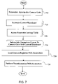
- FIG. 6 is a flowchart of method steps for performing an off-line procedure for determining optimized transformation parameters, in accordance with one embodiment of the present invention.
- FIG. 7 is a flowchart of method steps for performing an on-line procedure for utilizing optimized transformation parameters, in accordance with one embodiment of the present invention.
- the present invention relates to an improvement in data manipulation techniques.
- the following description is presented to enable one of ordinary skill in the art to make and use the invention and is provided in the context of a patent application and its requirements.
- Various modifications to the disclosed embodiments will be readily apparent to those skilled in the art, and the generic principles herein may be applied to other embodiments.
- the present invention is not intended to be limited to the embodiments shown, but is to be accorded the widest scope consistent with the principles and features described herein.
- the present invention comprises a system and method for effectively performing an image data transformation procedure, and may include an electronic camera device that is implemented to capture primary image data corresponding to a photographic target.
- a transformation manager in the electronic camera device may be configured to convert the primary image data into secondary image data by utilizing selectable transformation parameters that are optimized by utilizing an optimization metric to thereby minimize noise characteristics in the secondary image data.
- the transformation parameters may be stored in parameter lookup tables in the electronic camera device for use by the transformation manager in performing the image data transformation procedure.
- camera device 110 may include, but is not limited to, a capture subsystem 118 , a system bus 138 , and a control module 114 .
- capture subsystem 118 may be optically coupled to a target object, and may also be electrically coupled via system bus 138 to control module 114 .
- camera device 110 may readily include various other components in addition to, or instead of, those components discussed in conjunction with the FIG. 4 embodiment.
- the present invention may alternately be embodied in any appropriate type of electronic device other than the camera device 110 of FIG. 1 .
- camera device 110 may readily be implemented as a scanner device or a video camera device.
- control module 114 may preferably instruct capture subsystem 118 via system bus 138 to capture image data representing the target object.
- the captured image data may then be transferred over system bus 138 to control module 114 , which may responsively perform various processes and functions with the image data.
- System bus 138 may also bi-directionally pass various status and control signals between capture subsystem 118 and control module 114 .
- camera device 110 may include illuminant estimation means for determining an illuminant of the current target object.
- camera device 110 may estimate a current illuminant to be any appropriate lighting source, such as a particular color temperature of daylight, fluorescent light, or incandescent light.
- camera device 110 may include camera gain adjustment means for varying a camera gain of camera device 110 to compensate for brightness conditions on the current target object. For example, camera device 110 may increase the camera gain to compensate for dark lighting conditions of the target object, and may also decrease the camera gain to compensate for bright lighting conditions of the target object.
- capture subsystem 118 may include, but is not limited to, an image sensor that captures image data corresponding to the target object via reflected light impacting the image sensor along an optical path.
- the image sensor which may preferably include a charge-coupled device (CCD), may responsively generate a set of image data representing the target object.
- the image data may then be routed over system bus 138 to control module 114 for appropriate processing and storage.
- Other types of image capture sensors such as CMOS or linear arrays are also contemplated for capturing image data in conjunction with the present invention.
- the image capture sensors may include three or more primary color channels (for example, Red/Green/Blue (RGB), or Cyan/Magenta/Yellow/Green (C/M/Y/G) may be contemplated).
- control module 114 preferably includes, but is not limited to, a viewfinder 134 , a central processing unit (CPU) 122 , a memory 126 , and one or more input/output interface(s) (I/O) 130 .
- Viewfinder 134 , CPU 122 , memory 126 , and I/O 130 preferably are each coupled to, and communicate, via common system bus 138 that also communicates with capture subsystem 118 .
- control module 114 may readily include various other components in addition to, or instead of, those components discussed in conjunction with the FIG. 1 embodiment.
- CPU 122 may preferably be implemented to include any appropriate microprocessor device. Alternately, CPU 122 may be implemented using any other appropriate technology. For example, CPU 122 may be implemented to include certain application-specific integrated circuits (ASICs) or other appropriate electronic devices.
- Memory 126 may preferably be implemented as one or more appropriate storage devices, including, but not limited to, read-only memory, random-access memory, and various types of non-volatile memory, such as floppy disc devices, hard disc devices, or flash memory.
- I/O 130 preferably may provide one or more effective interfaces for facilitating bi-directional communications between camera device 110 and any external entity, including a system user or another electronic device. I/O 130 may be implemented using any appropriate input and/or output devices. The functionality and utilization of camera device 110 is further discussed below in conjunction with FIGS. 2-7 .
- memory 126 may preferably include, but is not limited to, a camera application 212 , an operating system 214 , a transformation manager 216 , RGB image data 218 , YCbCr image data 220 , compressed image data 222 , temporary storage 224 , and miscellaneous information 226 .
- memory 126 may readily include various other components in addition to, or instead of, those components discussed in conjunction with the FIG. 2 embodiment.
- camera application 212 may include program instructions that are preferably executed by CPU 122 ( FIG. 1 ) to perform various functions and operations for camera device 110 .
- the particular nature and functionality of camera application 212 preferably varies depending upon factors such as the type and particular use of the corresponding camera device 110 .
- operating system 214 preferably controls and coordinates low-level functionality of camera device 110 .
- transformation manager 216 may preferably control and coordinate one or more image data transformation procedures for image data captured by camera device 110 . The functionality of transformation manager 216 is further discussed below in conjunction with FIGS. 3-7 .
- RGB image data 218 , YCbCr image data 220 , and compressed image data 222 may include various formats of image data originally captured by camera device 110 .
- Temporary storage 224 may provide storage locations on a temporary basis for any appropriate type of information or data.
- Miscellaneous information 226 may include any desired software instructions, data, or other information for facilitating various functions performed by camera device 110 .
- transformation manager 216 may readily utilize various techniques that are different from those discussed in conjunction with the FIG. 3 embodiment.
- transformation manager 216 may utilize transformation parameters from transformation matrix 310 to convert RGB image data 218 (or other appropriate primary color image data) into corresponding YCbCr image data 220 .
- transformation manager 216 may similarly utilize transformation matrix 310 to convert primary color image data into appropriate formats other than YCbCr image data 220 .
- transformation matrix 310 may include a first row 314 of luminance transformation parameters, a second row 330 of Cb transformation parameters, and a third row 334 of Cr transformation parameters.
- the foregoing first row 314 of luminance transformation parameters may include a first luminance transformation parameter “a” ( 318 ), a second luminance transformation parameter “b” ( 322 ), and a third luminance transformation parameter “c” ( 326 ).
- transformation matrix 310 may utilize transformation matrix 310 to perform an image data transformation procedure to convert RGB image data 218 into YCbCr image data 220 to thereby facilitate a subsequent conversion of the YCbCr image data 220 into an appropriate type of compressed image data 222 , such as MPEG image data.
- the YCbCr format is a standard color space that is utilized the television industry.
- the foregoing image data transformation procedure may utilize conventional transformation parameters from a well-known “Recommendation 601 ” standard for calculating “Cb” with the second row 330 of Cb transformation parameters.
- Recommendation 601 is more formally known as Recommendation ITU-R (formerly CCIR) BT.601-4, “Encoding Parameters Of Digital Television For Studios” (Geneva: ITU, 1990).
- the foregoing image data transformation procedure may utilize conventional transformation parameters from the known “Recommendation 601 ” standard for calculating “Cr” with the third row 330 of Cr transformation parameters.
- the first row 314 of luminance transformation parameters may also be expressed alternately to represent the luminance transformation parameters.
- the first luminance transformation parameter “a” ( 318 ) may alternately be expressed as “k1”
- the second luminance transformation parameter “b” ( 322 ) may be expressed as “k2”.
- the present invention may also utilize a second luminance value “Y2” that may be combined with the foregoing first luminance value “Y1” in accordance with a combination transformation parameter “k3” to thereby produce a final luminance value “Y” for the YCbCr image data 220 .
- the second luminance value “Y2” may be a relatively unprocessed luminance value that may be determined in various appropriate manners.
- the second luminance value “Y2” may simply be a sum or an average of selected primary color values from the initially captured image data (for example, RGB image data or CMYG image data.
- the present invention may place certain transformation parameter limits upon the foregoing transformation parameters.
- “k1” may be limited according to the following formula: 0 ⁇ k1 ⁇ 1.
- “k2” may be limited according to the following formula: 0 ⁇ k2 ⁇ 1.
- third luminance transformation parameter “c” ( 326 ) may be limited according the following formula: 0 ⁇ (1 ⁇ k1 ⁇ k2) ⁇ 1, where the third luminance transformation parameter “c” ( 326 ) equals (1 ⁇ k1 ⁇ k2).
- the foregoing combination transformation parameter “k3” may be limited according to the following formula: 0 ⁇ k3 ⁇ 2.
- the luminance transformation parameters of “k1”, “k2”, and “k3” may advantageously be optimally selected to minimize various types of noise characteristics in the YCbCr image data 220 (and consequently in the corresponding final displayed images).
- the luminance transformation parameters of “k1”, “k2”, and “k3” may also be selected to minimize various types of color shift characteristics in the YCbCr image data 220 . The derivation and utilization of the foregoing transformation parameters is further discussed below in conjunction with FIGS. 4-7 .
- FIG. 4 a graph 410 illustrating one embodiment for determining a standard noise deviation is shown, in accordance with the present invention.
- the present invention may readily utilize various techniques that are different from those discussed in conjunction with the FIG. 4 embodiment.
- the luminance transformation parameters of “k1”, “k2”, and “k3” may advantageously be optimally selected to minimize various types of noise characteristics in the YCbCr image data 220 .
- an optimization metric must be derived to evaluate noise characteristics in the YCbCr image data 220 .
- the present invention may utilize any appropriate and effective techniques to derive one or more optimization metrics.
- an optimization metric may be derived by utilizing a patch set of representative color patches.
- a patch set of representative color patches For example, a standard MacBeth Color Checker chart of twenty-four different representative color patches may be utilized to derive an effective optimization metric.
- Each color patch from the patch set may be measured for a given camera gain, illuminant, and transformation parameters “k1”, “k2”, and “k3”.
- a noise variance value may then be calculated for each color patch in an appropriate color space (such as a standard L*a*b* color space).
- the foregoing optimization metric may then be calculated to be the average of all of the foregoing noise variance values for each of the color patches.
- graph 410 shows L* values from the L*a*b* color space on vertical axis 414 , and shows pixels across a given color patch on horizontal axis 418 .
- Graph 410 also shows an average L* value 422 .
- the color patches may initially be measured in a nonlinear YCbCr format which may then be converted into a linear L*a*b* format for deriving the optimization metric.
- a standard noise deviation 428 of noise around average L* value 422 is shown as being bounded by line 432 above average L* value 422 , and by line 436 below average L* value 422 .
- Standard noise deviation 428 may thus be determined by measuring noise values above and below average L* value 422 .
- an optimization metric may also include information from other measured values from the color patches. For example, an optimization metric may include information from a* values and/or b* values from the L*a*b* color space.
- the foregoing optimization metric may be utilized to optimize the selection of transformation parameters “k1”, “k2”, “k3” to advantageously minimize noise characteristics in YCbCr image data 220 . More specifically, a minimum value of the optimization metric may be sought by altering transformation parameters “k1”, “k2”, “k3” for various camera gains and illuminants. The foregoing minimum value of the optimization metric may be determined in any effective manner. For example, a simple trial-and-error approach may be utilized, or a more intelligent “path of steepest descent” technique may be iteratively applied to locate the minimum value for the optimization metric.
- a parameter lookup table may be implemented for accessing or interpolating appropriate optimized transformation parameters “k1”, “k2”, “k3” for use in performing an image data transformation procedure by camera device 110 .
- a parameter lookup table is discussed below in conjunction with FIG. 5 .
- parameter lookup table 510 a diagram for one embodiment of a parameter lookup table 510 is shown, in accordance with the present invention.
- the parameter lookup table 510 of FIG. 5 is presented for purposes of illustration, and in alternate embodiments of the present invention, parameter lookup table 510 may readily include other elements and components in various configurations that are different from that discussed in conjunction with the FIG. 5 embodiment.
- a first column 534 shows a series of k1 values for various illuminants A through E that are shown in corresponding rows 514 through 530 .
- a second column 538 shows a series of k2 values for illuminants A through E in rows 514 through 530 .
- a third column 542 also shows a series of k3 values for illuminants A through E in rows 514 through 530 .
- the FIG. 5 parameter lookup table 510 shows only five illuminants. However, in alternate embodiments, any desired number or types of illuminants may be included.
- the FIG. 5 lookup table 510 provides optimized transformation parameters for a camera gain of one (unity).
- additional parameter lookup tables 510 may readily be implemented for any desired number of other camera gains.
- parameter lookup tables 510 may advantageously be implemented in a minimized format that includes a relatively smaller number of entries.
- transformation manager 216 may then utilize various effective interpolation techniques to interpolate additional optimized transformation parameters for gains or illuminants that are not specifically listed in lookup tables 510 .
- transformation manager 216 may also derive additional optimized transformation parameters by utilizing one or more mathematical formulas or algorithms that describe characteristics or relationships of the transformation parameters in lookup tables 510 .
- FIG. 6 a flowchart of method steps for performing an off-line design procedure to determine optimized transformation parameters is shown, in accordance with one embodiment of the present invention.
- the FIG. 6 embodiment is presented for purposes of illustration, and in alternate embodiments, the present invention may readily utilize various other steps and sequences than those discussed in conjunction with the FIG. 6 embodiment.
- step 612 parameter limits may be defined to specify desired ranges for the optimized transformation parameters to perform image data transformation procedures.
- an optimization metric may be defined for evaluating a representative patch set of color patches.
- step 620 a current illuminant of the representative patch set may be measured and recorded.
- step 624 each of the color patches from the representative patch set may be measured to determine various desired color and brightness characteristics.
- step 628 in accordance with the present invention, the various optimized transformation parameters may be carefully selected to minimize the optimization metric which thereby minimizes noise characteristics in the corresponding image data.
- step 632 if optimized transformation parameters remain to be selected for additional illuminants, then the FIG. 6 process may return to step 620 through 632 to repeatedly select additional optimized transformation parameters for each additional illuminant.
- step 636 when optimized transformation parameters have been selected for each illuminant, then a parameter lookup table 510 may be created for the current camera gain.
- the FIG. 6 process may then terminate. However, in accordance with the present invention, the FIG. 6 process may typically be repeated for any desired number of camera gains to thereby produce a complete set of parameter lookup tables 510 for utilization by camera device 110 in performing image data transformation procedures.
- One embodiments for utilizing parameter lookup tables 510 is discussed below in conjunction with FIG. 7 .
- FIG. 7 a flowchart of method steps for performing an on-line procedure to utilize optimized transformation parameters is shown, in accordance with one embodiment of the present invention.
- the FIG. 7 embodiment is presented for purposes of illustration, and in alternate embodiments, the present invention may readily utilize various other steps and sequences than those discussed in conjunction with the FIG. 7 embodiment.
- an appropriate camera gain may initially be determined and stored by camera device 110 , depending upon current lighting conditions of a desired photographic target. Then, in step 716 , camera device 110 may estimate a current illuminant of the photographic target. In step 720 , transformation manager 216 of camera device 110 may access one or more parameter lookup tables 510 containing optimized transformation parameters for performing an image data transformation procedure.
- transformation manager 216 may utilize the parameter lookup tables 510 to interpolate optimized transformation parameters that are closest to the current camera gain and current illuminant of the photographic target.
- transformation manager 216 may load camera registers of camera device 110 with the appropriate optimized transformation parameters obtained in foregoing step 724 .
- transformation manager 216 may utilize the optimized transformation parameters to perform one or more image data transformation procedures, in accordance with the present invention. The FIG. 7 process may then terminate.
Landscapes
- Engineering & Computer Science (AREA)
- Multimedia (AREA)
- Signal Processing (AREA)
- Health & Medical Sciences (AREA)
- Biomedical Technology (AREA)
- General Health & Medical Sciences (AREA)
- Image Processing (AREA)
- Facsimile Image Signal Circuits (AREA)
- Processing Of Color Television Signals (AREA)
- Color Image Communication Systems (AREA)
- Picture Signal Circuits (AREA)
Priority Applications (6)
| Application Number | Priority Date | Filing Date | Title |
|---|---|---|---|
| US10/721,628 US7277575B2 (en) | 2003-11-25 | 2003-11-25 | System and method for effectively performing an image data transformation procedure |
| CN2004800345321A CN101019131B (zh) | 2003-11-25 | 2004-11-18 | 有效完成图像数据变换过程的系统和方法 |
| EP04811468.0A EP1687689B1 (en) | 2003-11-25 | 2004-11-18 | System and method for effectively performing an image data transformation procedure |
| PCT/US2004/038756 WO2005052741A2 (en) | 2003-11-25 | 2004-11-18 | System and method for effectively performing an image data transformation procedure |
| JP2006541382A JP2007515876A (ja) | 2003-11-25 | 2004-11-18 | 画像データ変換処理を効果的に実行する画像データ変換処理システム及び画像データ変換処理方法 |
| KR1020067010089A KR101137611B1 (ko) | 2003-11-25 | 2004-11-18 | 이미지 데이터 변환 절차를 효과적으로 수행하는 시스템 및 방법 |
Applications Claiming Priority (1)
| Application Number | Priority Date | Filing Date | Title |
|---|---|---|---|
| US10/721,628 US7277575B2 (en) | 2003-11-25 | 2003-11-25 | System and method for effectively performing an image data transformation procedure |
Publications (2)
| Publication Number | Publication Date |
|---|---|
| US20050110876A1 US20050110876A1 (en) | 2005-05-26 |
| US7277575B2 true US7277575B2 (en) | 2007-10-02 |
Family
ID=34591844
Family Applications (1)
| Application Number | Title | Priority Date | Filing Date |
|---|---|---|---|
| US10/721,628 Active 2025-03-06 US7277575B2 (en) | 2003-11-25 | 2003-11-25 | System and method for effectively performing an image data transformation procedure |
Country Status (6)
| Country | Link |
|---|---|
| US (1) | US7277575B2 (zh) |
| EP (1) | EP1687689B1 (zh) |
| JP (1) | JP2007515876A (zh) |
| KR (1) | KR101137611B1 (zh) |
| CN (1) | CN101019131B (zh) |
| WO (1) | WO2005052741A2 (zh) |
Cited By (4)
| Publication number | Priority date | Publication date | Assignee | Title |
|---|---|---|---|---|
| US20080278601A1 (en) * | 2007-05-07 | 2008-11-13 | Nvidia Corporation | Efficient Determination of an Illuminant of a Scene |
| US20080297620A1 (en) * | 2007-06-04 | 2008-12-04 | Nvidia Corporation | Reducing Computational Complexity in Determining an Illuminant of a Scene |
| US20090162042A1 (en) * | 2007-12-24 | 2009-06-25 | Microsoft Corporation | Guided photography based on image capturing device rendered user recommendations |
| US9870598B2 (en) | 2013-04-26 | 2018-01-16 | Nvidia Corporation | Low complexity adaptive filtering for mobile captures |
Families Citing this family (3)
| Publication number | Priority date | Publication date | Assignee | Title |
|---|---|---|---|---|
| US7576797B2 (en) * | 2001-06-25 | 2009-08-18 | Texas Instruments Incorporated | Automatic white balancing via illuminant scoring autoexposure by neural network mapping |
| US8320698B2 (en) * | 2008-09-18 | 2012-11-27 | Sony Corporation | System and method for denoising using signal dependent adaptive weights |
| US20190139189A1 (en) * | 2017-11-06 | 2019-05-09 | Qualcomm Incorporated | Image remosaicing |
Citations (6)
| Publication number | Priority date | Publication date | Assignee | Title |
|---|---|---|---|---|
| US5805213A (en) * | 1995-12-08 | 1998-09-08 | Eastman Kodak Company | Method and apparatus for color-correcting multi-channel signals of a digital camera |
| US5850472A (en) * | 1995-09-22 | 1998-12-15 | Color And Appearance Technology, Inc. | Colorimetric imaging system for measuring color and appearance |
| US6049626A (en) * | 1996-10-09 | 2000-04-11 | Samsung Electronics Co., Ltd. | Image enhancing method and circuit using mean separate/quantized mean separate histogram equalization and color compensation |
| US6151136A (en) | 1997-04-18 | 2000-11-21 | Fuji Photo Film Co., Ltd. | Color transforming method |
| US6459425B1 (en) * | 1997-08-25 | 2002-10-01 | Richard A. Holub | System for automatic color calibration |
| US6505002B2 (en) * | 2000-12-22 | 2003-01-07 | Eastman Kodak Company | Camera that displays predominant color multi-color scene and/or multi-color captured image of scene |
Family Cites Families (8)
| Publication number | Priority date | Publication date | Assignee | Title |
|---|---|---|---|---|
| JPH0373005A (ja) * | 1989-08-12 | 1991-03-28 | Eimu Kenkyusho:Kk | 予定日の予告および行事日の演出装置付のマイコンつきの照明装置 |
| JP2827410B2 (ja) * | 1990-03-14 | 1998-11-25 | ソニー株式会社 | デイジタルデータの高能率符号化方法 |
| KR100230261B1 (ko) * | 1996-10-09 | 1999-11-15 | 윤종용 | 양자화된 평균 분리 히스토그램 등화와 칼라 보상을 이용한 칼라신호의 화질 개선방법 및 그 회로 |
| US6600833B1 (en) * | 1999-07-23 | 2003-07-29 | Intel Corporation | Methodology for color correction with noise regulation |
| JP3706789B2 (ja) | 2000-05-12 | 2005-10-19 | キヤノン株式会社 | 信号処理装置及び信号処理方法 |
| US7265781B2 (en) * | 2001-08-22 | 2007-09-04 | Fujifilm Corporation | Method and apparatus for determining a color correction matrix by minimizing a color difference maximum or average value |
| JP2003125226A (ja) * | 2001-10-18 | 2003-04-25 | Seiko Epson Corp | 色変換方法、色変換装置および色変換処理プログラム |
| JP2003198860A (ja) | 2001-10-18 | 2003-07-11 | Seiko Epson Corp | 色変換方法、色変換装置、色変換行列生成方法および色変換行列生成プログラム |
-
2003
- 2003-11-25 US US10/721,628 patent/US7277575B2/en active Active
-
2004
- 2004-11-18 KR KR1020067010089A patent/KR101137611B1/ko active IP Right Grant
- 2004-11-18 WO PCT/US2004/038756 patent/WO2005052741A2/en not_active Application Discontinuation
- 2004-11-18 EP EP04811468.0A patent/EP1687689B1/en active Active
- 2004-11-18 CN CN2004800345321A patent/CN101019131B/zh active Active
- 2004-11-18 JP JP2006541382A patent/JP2007515876A/ja active Pending
Patent Citations (6)
| Publication number | Priority date | Publication date | Assignee | Title |
|---|---|---|---|---|
| US5850472A (en) * | 1995-09-22 | 1998-12-15 | Color And Appearance Technology, Inc. | Colorimetric imaging system for measuring color and appearance |
| US5805213A (en) * | 1995-12-08 | 1998-09-08 | Eastman Kodak Company | Method and apparatus for color-correcting multi-channel signals of a digital camera |
| US6049626A (en) * | 1996-10-09 | 2000-04-11 | Samsung Electronics Co., Ltd. | Image enhancing method and circuit using mean separate/quantized mean separate histogram equalization and color compensation |
| US6151136A (en) | 1997-04-18 | 2000-11-21 | Fuji Photo Film Co., Ltd. | Color transforming method |
| US6459425B1 (en) * | 1997-08-25 | 2002-10-01 | Richard A. Holub | System for automatic color calibration |
| US6505002B2 (en) * | 2000-12-22 | 2003-01-07 | Eastman Kodak Company | Camera that displays predominant color multi-color scene and/or multi-color captured image of scene |
Cited By (10)
| Publication number | Priority date | Publication date | Assignee | Title |
|---|---|---|---|---|
| US20080278601A1 (en) * | 2007-05-07 | 2008-11-13 | Nvidia Corporation | Efficient Determination of an Illuminant of a Scene |
| US8564687B2 (en) * | 2007-05-07 | 2013-10-22 | Nvidia Corporation | Efficient determination of an illuminant of a scene |
| US20080297620A1 (en) * | 2007-06-04 | 2008-12-04 | Nvidia Corporation | Reducing Computational Complexity in Determining an Illuminant of a Scene |
| US20100103289A1 (en) * | 2007-06-04 | 2010-04-29 | Nvidia Corporation | Reducing computational complexity in determining an illuminant of a scene |
| US8698917B2 (en) | 2007-06-04 | 2014-04-15 | Nvidia Corporation | Reducing computational complexity in determining an illuminant of a scene |
| US8760535B2 (en) | 2007-06-04 | 2014-06-24 | Nvidia Corporation | Reducing computational complexity in determining an illuminant of a scene |
| US20090162042A1 (en) * | 2007-12-24 | 2009-06-25 | Microsoft Corporation | Guided photography based on image capturing device rendered user recommendations |
| US7805066B2 (en) | 2007-12-24 | 2010-09-28 | Microsoft Corporation | System for guided photography based on image capturing device rendered user recommendations according to embodiments |
| TWI450111B (zh) * | 2007-12-24 | 2014-08-21 | Microsoft Corp | 用於基於影像捕捉裝置呈現的使用者建議之導引式攝影術之方法、電腦可使用媒體、及裝置 |
| US9870598B2 (en) | 2013-04-26 | 2018-01-16 | Nvidia Corporation | Low complexity adaptive filtering for mobile captures |
Also Published As
| Publication number | Publication date |
|---|---|
| KR101137611B1 (ko) | 2012-04-19 |
| EP1687689B1 (en) | 2019-03-27 |
| JP2007515876A (ja) | 2007-06-14 |
| EP1687689A4 (en) | 2010-09-22 |
| KR20060131754A (ko) | 2006-12-20 |
| EP1687689A2 (en) | 2006-08-09 |
| WO2005052741A2 (en) | 2005-06-09 |
| CN101019131B (zh) | 2011-08-03 |
| US20050110876A1 (en) | 2005-05-26 |
| CN101019131A (zh) | 2007-08-15 |
| WO2005052741A3 (en) | 2006-10-05 |
Similar Documents
| Publication | Publication Date | Title |
|---|---|---|
| US6788813B2 (en) | System and method for effectively performing a white balance operation | |
| US7643068B2 (en) | White balance control method, white balance control apparatus and image-taking apparatus | |
| US7218344B2 (en) | System and method for efficiently performing a white balance operation | |
| US8803994B2 (en) | Adaptive spatial sampling using an imaging assembly having a tunable spectral response | |
| US20040212691A1 (en) | Automatic white balance adjusting method | |
| US8629919B2 (en) | Image capture with identification of illuminant | |
| US8982236B2 (en) | Imaging apparatus | |
| US20070223059A1 (en) | Image pickup apparatus and a method for producing an image of quality matching with a scene to be captured | |
| JP5165300B2 (ja) | 映像処理装置および映像処理プログラム | |
| JP2006211478A (ja) | 撮像装置および撮像素子 | |
| JP2007053499A (ja) | ホワイトバランス制御装置及び撮像装置 | |
| US20100295977A1 (en) | Image processor and recording medium | |
| US20100238317A1 (en) | White balance processing apparatus, method for processing white balance, and white balance processing program | |
| US9160999B2 (en) | Image processing device and imaging device | |
| US7277575B2 (en) | System and method for effectively performing an image data transformation procedure | |
| US8687091B2 (en) | Image capturing systems and methods utilizing customizable look management | |
| Brown | Color processing for digital cameras | |
| JP5552795B2 (ja) | 撮像装置、画像処理装置およびプログラム | |
| JP4718113B2 (ja) | ホワイトバランス調整方法および画像処理装置 | |
| JP2006333113A (ja) | 撮像装置 | |
| US20040119860A1 (en) | Method of colorimetrically calibrating an image capturing device | |
| US20120154625A1 (en) | Image processing apparatus, image processing method, and program recording medium | |
| KR20140077098A (ko) | 촬상 장치 및 촬상 방법 | |
| JP2012065069A (ja) | 欠陥検出補正装置、及びプログラム、並びに記憶媒体 | |
| US20050018054A1 (en) | Chroma compensation circuit and its method |
Legal Events
| Date | Code | Title | Description |
|---|---|---|---|
| AS | Assignment |
Owner name: SONY ELECTRONICS INC., NEW JERSEY Free format text: ASSIGNMENT OF ASSIGNORS INTEREST;ASSIGNORS:BAQAI, FARHAN A.;COOPER, TED J.;MATSUI, AKIRA;AND OTHERS;REEL/FRAME:014748/0334;SIGNING DATES FROM 20031124 TO 20031125 Owner name: SONY CORPORATION, JAPAN Free format text: ASSIGNMENT OF ASSIGNORS INTEREST;ASSIGNORS:BAQAI, FARHAN A.;COOPER, TED J.;MATSUI, AKIRA;AND OTHERS;REEL/FRAME:014748/0334;SIGNING DATES FROM 20031124 TO 20031125 |
|
| STCF | Information on status: patent grant |
Free format text: PATENTED CASE |
|
| FEPP | Fee payment procedure |
Free format text: PAYER NUMBER DE-ASSIGNED (ORIGINAL EVENT CODE: RMPN); ENTITY STATUS OF PATENT OWNER: LARGE ENTITY Free format text: PAYOR NUMBER ASSIGNED (ORIGINAL EVENT CODE: ASPN); ENTITY STATUS OF PATENT OWNER: LARGE ENTITY |
|
| FPAY | Fee payment |
Year of fee payment: 4 |
|
| FPAY | Fee payment |
Year of fee payment: 8 |
|
| MAFP | Maintenance fee payment |
Free format text: PAYMENT OF MAINTENANCE FEE, 12TH YEAR, LARGE ENTITY (ORIGINAL EVENT CODE: M1553); ENTITY STATUS OF PATENT OWNER: LARGE ENTITY Year of fee payment: 12 |