US7275390B2 - Desiccant cartridge for an integrated condenser/receiver and method of making same - Google Patents
Desiccant cartridge for an integrated condenser/receiver and method of making same Download PDFInfo
- Publication number
- US7275390B2 US7275390B2 US10/511,356 US51135604A US7275390B2 US 7275390 B2 US7275390 B2 US 7275390B2 US 51135604 A US51135604 A US 51135604A US 7275390 B2 US7275390 B2 US 7275390B2
- Authority
- US
- United States
- Prior art keywords
- rigid
- desiccant
- stand
- porous
- recited
- Prior art date
- Legal status (The legal status is an assumption and is not a legal conclusion. Google has not performed a legal analysis and makes no representation as to the accuracy of the status listed.)
- Expired - Fee Related, expires
Links
Images


Classifications
-
- B—PERFORMING OPERATIONS; TRANSPORTING
- B01—PHYSICAL OR CHEMICAL PROCESSES OR APPARATUS IN GENERAL
- B01D—SEPARATION
- B01D53/00—Separation of gases or vapours; Recovering vapours of volatile solvents from gases; Chemical or biological purification of waste gases, e.g. engine exhaust gases, smoke, fumes, flue gases, aerosols
- B01D53/02—Separation of gases or vapours; Recovering vapours of volatile solvents from gases; Chemical or biological purification of waste gases, e.g. engine exhaust gases, smoke, fumes, flue gases, aerosols by adsorption, e.g. preparative gas chromatography
- B01D53/04—Separation of gases or vapours; Recovering vapours of volatile solvents from gases; Chemical or biological purification of waste gases, e.g. engine exhaust gases, smoke, fumes, flue gases, aerosols by adsorption, e.g. preparative gas chromatography with stationary adsorbents
- B01D53/0407—Constructional details of adsorbing systems
- B01D53/0431—Beds with radial gas flow
-
- B—PERFORMING OPERATIONS; TRANSPORTING
- B01—PHYSICAL OR CHEMICAL PROCESSES OR APPARATUS IN GENERAL
- B01D—SEPARATION
- B01D53/00—Separation of gases or vapours; Recovering vapours of volatile solvents from gases; Chemical or biological purification of waste gases, e.g. engine exhaust gases, smoke, fumes, flue gases, aerosols
- B01D53/02—Separation of gases or vapours; Recovering vapours of volatile solvents from gases; Chemical or biological purification of waste gases, e.g. engine exhaust gases, smoke, fumes, flue gases, aerosols by adsorption, e.g. preparative gas chromatography
- B01D53/04—Separation of gases or vapours; Recovering vapours of volatile solvents from gases; Chemical or biological purification of waste gases, e.g. engine exhaust gases, smoke, fumes, flue gases, aerosols by adsorption, e.g. preparative gas chromatography with stationary adsorbents
- B01D53/0407—Constructional details of adsorbing systems
- B01D53/0415—Beds in cartridges
-
- B—PERFORMING OPERATIONS; TRANSPORTING
- B01—PHYSICAL OR CHEMICAL PROCESSES OR APPARATUS IN GENERAL
- B01D—SEPARATION
- B01D53/00—Separation of gases or vapours; Recovering vapours of volatile solvents from gases; Chemical or biological purification of waste gases, e.g. engine exhaust gases, smoke, fumes, flue gases, aerosols
- B01D53/26—Drying gases or vapours
- B01D53/261—Drying gases or vapours by adsorption
-
- F—MECHANICAL ENGINEERING; LIGHTING; HEATING; WEAPONS; BLASTING
- F25—REFRIGERATION OR COOLING; COMBINED HEATING AND REFRIGERATION SYSTEMS; HEAT PUMP SYSTEMS; MANUFACTURE OR STORAGE OF ICE; LIQUEFACTION SOLIDIFICATION OF GASES
- F25B—REFRIGERATION MACHINES, PLANTS OR SYSTEMS; COMBINED HEATING AND REFRIGERATION SYSTEMS; HEAT PUMP SYSTEMS
- F25B39/00—Evaporators; Condensers
- F25B39/04—Condensers
-
- F—MECHANICAL ENGINEERING; LIGHTING; HEATING; WEAPONS; BLASTING
- F25—REFRIGERATION OR COOLING; COMBINED HEATING AND REFRIGERATION SYSTEMS; HEAT PUMP SYSTEMS; MANUFACTURE OR STORAGE OF ICE; LIQUEFACTION SOLIDIFICATION OF GASES
- F25B—REFRIGERATION MACHINES, PLANTS OR SYSTEMS; COMBINED HEATING AND REFRIGERATION SYSTEMS; HEAT PUMP SYSTEMS
- F25B43/00—Arrangements for separating or purifying gases or liquids; Arrangements for vaporising the residuum of liquid refrigerant, e.g. by heat
- F25B43/003—Filters
-
- B—PERFORMING OPERATIONS; TRANSPORTING
- B01—PHYSICAL OR CHEMICAL PROCESSES OR APPARATUS IN GENERAL
- B01D—SEPARATION
- B01D2257/00—Components to be removed
- B01D2257/80—Water
-
- B—PERFORMING OPERATIONS; TRANSPORTING
- B01—PHYSICAL OR CHEMICAL PROCESSES OR APPARATUS IN GENERAL
- B01D—SEPARATION
- B01D2259/00—Type of treatment
- B01D2259/45—Gas separation or purification devices adapted for specific applications
- B01D2259/4566—Gas separation or purification devices adapted for specific applications for use in transportation means
-
- F—MECHANICAL ENGINEERING; LIGHTING; HEATING; WEAPONS; BLASTING
- F25—REFRIGERATION OR COOLING; COMBINED HEATING AND REFRIGERATION SYSTEMS; HEAT PUMP SYSTEMS; MANUFACTURE OR STORAGE OF ICE; LIQUEFACTION SOLIDIFICATION OF GASES
- F25B—REFRIGERATION MACHINES, PLANTS OR SYSTEMS; COMBINED HEATING AND REFRIGERATION SYSTEMS; HEAT PUMP SYSTEMS
- F25B2339/00—Details of evaporators; Details of condensers
- F25B2339/04—Details of condensers
- F25B2339/044—Condensers with an integrated receiver
- F25B2339/0441—Condensers with an integrated receiver containing a drier or a filter
-
- F—MECHANICAL ENGINEERING; LIGHTING; HEATING; WEAPONS; BLASTING
- F25—REFRIGERATION OR COOLING; COMBINED HEATING AND REFRIGERATION SYSTEMS; HEAT PUMP SYSTEMS; MANUFACTURE OR STORAGE OF ICE; LIQUEFACTION SOLIDIFICATION OF GASES
- F25B—REFRIGERATION MACHINES, PLANTS OR SYSTEMS; COMBINED HEATING AND REFRIGERATION SYSTEMS; HEAT PUMP SYSTEMS
- F25B2400/00—General features or devices for refrigeration machines, plants or systems, combined heating and refrigeration systems or heat-pump systems, i.e. not limited to a particular subgroup of F25B
- F25B2400/16—Receivers
- F25B2400/162—Receivers characterised by the plug or stop
Definitions
- the invention relates to a desiccant-containing package for use in an integrated condenser/receiver, and more particularly, to a desiccant-containing package comprising a porous desiccant bag (most preferably, a desiccant-containing packet or bag) secured to a rigid member.
- a desiccant-containing package comprising a porous desiccant bag (most preferably, a desiccant-containing packet or bag) secured to a rigid member.
- Desiccant-containing packages have been employed in small diameter receivers that are juxtaposed along one of the condenser headers in an integrated condenser/receiver for an automotive air-conditioning system or the like.
- These integrated condenser/receiver structures eliminate the need for separate tubing to connect the condenser with the receiver and have become popular due to their reduced spatial requirements as compared with earlier designs.
- the overall dimensions of one integrated condenser/receiver proposed in U.S. Pat. No. 5,813,249 [hereinafter the “'249 patent”] are from about 300 mm-400 mm in height and about 300 mm-600 mm in width.
- the axes of the receiver canister and the associated header lie parallel to that of the canister attached to, and contiguous with, the header.
- the desiccant-containing package positioned in the receiver dries refrigerant fluid (and the oil and moisture entrained therein) before the dried refrigerant enters a supercooler unit formed integrally with the condenser. Ultimately, the desiccant material is spent, that is, saturated with contaminants, and must be replaced.
- U.S. Provisional Patent Application 60/178,595 discloses a desiccant containing package comprising a pouch preferably formed from a tube of porous polyester felt material. During manufacture, one end of the tube is sealed, preferably by tucking a portion of the tube side wall and flattening the end portion under conditions which cause the polyester fibers to fuse together and seal the end of the pouch. Desiccant material then is poured into the pouch. Most preferably, the open end of the pouch then is ultrasonically welded to an attachment ring of filter cap.
- U.S. Pat. No. 5,666,791 proposes an insert for a vehicle air conditioner.
- the insert is composed of two parts. One part contains a filter screen. The other part is an extension part bridging the distance from the filter screen to a detachable cover of the receiver.
- the part which contains the filter screen and which requires higher manufacturing expenditures may be standardized for several sizes of condensers so that it can be produced in the same shape in large piece numbers.
- the part containing the filter screen is supplemented by an extension part which has a relatively simple shape and can therefore be produced at a reasonable price in different lengths by means of a modular-construction tool.
- the construction reduces the amount of waste to be disposed of when the desiccant is spent because it will be sufficient to exchange and dispose of the part with the filter screen.
- the insert as a whole is likely to be relatively complex and expensive to produce.
- the container is provided on the inside with a supporting screen.
- the container which is made of plastic, is molded around this supporting screen.
- the supporting screen may consist of plastic or of a special steel, the former having the advantage of being recyclable.
- a filter screen comprising a filter nonwoven material or a needle felt is assembled into the container. This mode of manufacture involves multiple component parts and several manufacturing steps, the combination of which likely increases the cost of manufacture.
- U.S. Pat. No. 6,170,287 proposes that a tube of desiccant material be installed and located within a receiver canister by a stand-off comprised of a tight-fitting, notched, disk-shaped base and a narrow central post which is comparable in length to the height of the inlet above the lower end cap.
- the tight fit allows the tube to be inserted up into the canister, well away from the bottom of the canister and free of heat damage as an end cap of the canister is attached. Later, in operation, the central post keeps the tube located clear of inlet and outlet ports of the canister.
- U.S. Pat. No. 6,360,560 proposes a condenser with an integral receiver dryer.
- the receiver dryer includes a dryer capsule for removing moisture from the refrigerant fluid.
- One drawback to the dryer capsule proposed in the reference is its relative complexity and likely expense of manufacture.
- the dryer capsule proposed in U.S. Pat. No. 6,360,560 is generally cylindrical in shape and includes a base, a housing extending axially from the base and a cap closing an end of the housing.
- the base is disposed adjacent a seat wall to create a seal and prevent fluid from passing therebetween.
- the housing has a plurality of apertures extending therethrough and a filter covering the apertures.
- the dryer capsule includes a quantity of dryer material such as desiccant disposed within the housing.
- the cap has a loop with an aperture extending therethrough to allow a tool to engage the loop to remove the dryer capsule from the receiver dryer.
- the loop also acts as a spring to hold the base of the dryer capsule against the seat wall when an end closure is in place over an open end of the receiver dryer.
- the end closure proposed in U.S. Pat. No. 6,360,560 has a head extending radially and a threaded shaft extending axially.
- the end closure also includes a seal disposed about the threaded shaft and adjacent the head.
- the threaded shaft engages the threaded open end such that the seal engages the side and the head overlaps the side bounding the open end.
- a preferred desiccant cartridge comprises a porous desiccant bag and a rigid member.
- a preferred porous desiccant bag defines sealed first and second end portions, at least one of which has a flat seal. The flat seal of the porous desiccant bag is secured to the tab portion of the rigid member.
- a preferred desiccant cartridge comprises a rigid, preferably plastic, stand-off member and a porous desiccant bag or packet.
- the preferred rigid stand-off member comprises an inner pad portion, an elongated stand-off portion terminating in the inner pad portion and an outer pad portion spaced from the inner pad portion.
- the porous desiccant bag is positioned between the inner and outer pads and affixed to one or both of the inner and outer pad portions.
- the rigid member is a rigid dongle including a skirt portion.
- a web portion closes an end of the skirt portion to form a cavity.
- One or more holes extending through the skirt portion from the cavity to an exterior surface of the skirt portion facilitate removal of the desiccant cartridge from the reservoir.
- the rigid stand-off member further comprises a spacer bar portion and a clamp portion supported by the spacer bar portion for securing the porous desiccant bag.
- the preferred clamp portion includes a first clamping jaw supported by the spacer bar portion and a second clamping jaw supported by the first clamping jaw through a living hinge.
- the first and second clamping jaws each define complementary detents for engagement to secure the porous desiccant bag in the clamp portion.
- the first and second clamping jaws each define an outer annular channel for receiving an annular seal. This allows the clamp portion to act as a baffle preventing flow through the integrated condenser/receiver from bypassing desiccant material in the porous desiccant bag.
- the rigid stand-off member further comprises a cage portion extending between the first and second pad portions.
- the preferred cage portion includes a first cage element coupled to the inner and outer pad portions.
- the preferred cage portion further includes a second cage element supported by the first cage element through a living hinge.
- the first and second cage elements define complementary detents for engagement to secure the porous desiccant bag in the cage portion.
- the first and second cage elements each comprise a plurality of annularly-arrayed spacer bars extending between the inner and outer pad portions as well as a plurality of hoops extending transversely of the plurality of annularly-arrayed spacer bars.
- the rigid stand-off member is cast as a unitary member from a suitable plastic or polymeric material.
- the porous desiccant bag which preferably comprises a porous desiccant packet or bag, is affixed to one or both of the inner and outer pad portions.
- Preferred means for affixing the porous desiccant bag to the inner and outer pad portions include ultrasonic welding, although other means (such as thermal or vibration welding) will be apparent to those of ordinary skill in the art.
- the rigid stand-off member includes a clamp portion or a cage portion
- the clamp or cage portion is closed so as to engage the complementary detents to secure the porous desiccant bag.
- the structure of the rigid member serves to reduce the likelihood that the porous desiccant bag will be damaged as the rigid member is welded to the porous desiccant bag.
- the flat end seat which is to be welded to the tab portion of the rigid member is extended away from the bulk of the porous desiccant bag to protect the bulk of the porous desiccant bag from the energy used to form the weld.
- Another advantage of the preferred desiccant cartridge is that it facilitates installation and removal of the porous desiccant bag.
- Inner and outer pad portions guide the porous desiccant bag into and out of the receiver during installation and removal.
- the combination of the inner and outer pad portions with the clamp or cage portions serve to immobilize the porous desiccant bag relative to the rigid stand-off member so as to promote smooth installation and removal.
- the preferred desiccant cartridge is pressed through an open end of the reservoir so as to abut the spacer portion of the rigid cap against an end panel of the receiver.
- a demountable end closure or plug is engaged with an open end of the reservoir to provide fluid-tight closure of the receiver.
- an elongated, relatively thin stand-off portion of either the rigid member or the end closure serves to position the desiccant cartridge in the reservoir.
- the desiccant cartridge is extracted from the reservoir by removing the demountable cap and then engaging a hook with a hole or eye defined in the rigid member so as to pull the desiccant cartridge from the reservoir.
- the preferred desiccant cartridge minimizes the extraneous material which must be discarded with a spent desiccant bag.
- the preferred desiccant cartridge that is, the rigid stand-off member and the porous desiccant bag, can be removed from the receiver as a unit. Even assuming that the rigid stand-off member then is disposed of with the porous desiccant bag, the simplicity of the preferred rigid stand-off minimizes the amount of extraneous material which is discarded.
- the preferred desiccant cartridge comprises a rigid, preferably plastic, stand-off member and a porous desiccant bag or pouch.
- the preferred rigid stand-off member comprises an inner pad portion, an elongated stand-off portion terminating in the inner pad portion and an attachment tab extending transversely to from the inner pad portion.
- the porous desiccant bag includes first and second flat end seals, one of which is secured to the attachment tab.
- the porous desiccant bag is manufactured by forming the first flat end seal in a first open end of a porous tube, as by ultrasonic welding; pouring desiccant into the porous tube; and forming the second flat end seal in a second open end of the porous tube.
- the rigid stand-off member is molded as a single piece. Then, the first or second flat end seal is secured to the attachment tab of the rigid stand-off member, as by ultrasonic welding. During this welding process, the first or second flat end seal is extended away from the bulk of the porous desiccant bag, so as to minimize damage to the porous desiccant bag during welding.
- Still other embodiments of the desiccant cartridge comprise a porous cap in addition to the rigid stand-off member and porous desiccant bag.
- the preferred rigid cap defines a cavity which receives the second end portion of the porous desiccant bag.
- the rigid cap also defines a plurality of perforations or holes which communicate between the cavity and an exterior of the rigid cap. This plurality of holes permits fluid to flow from the porous desiccant bag through the rigid cap. It is desirable that these holes be so dimensioned as to permit the flow of refrigerant fluid while retaining the desiccant material and inhibiting the flow of moisture, oil and other contaminants. In this manner, the perforations provide additional filtering of the refrigerant fluid which percolates through the desiccant material in the porous desiccant bag.
- the rigid cap also defines a spacer portion extending away from the cavity defined in the rigid cap.
- the spacer is designed to abut against an end panel of the receiver to help position the desiccant cartridge in the reservoir.
- the rigid stand-off member and the rigid cap are each molded as one-piece castings from suitable plastic or polymeric materials.
- the preferred rigid stand-off member includes a tab portion which extends transversely from the inner pad portion in a direction opposite that of the elongated stand-off portion.
- the first end portion of the porous desiccant bag takes the form of a flat end seal which is secured to the tab portion of the rigid stand-off member.
- Preferred means for affixing the flat end seal of the porous desiccant bag to the tab portion of the rigid stand-off member include ultrasonic welding, although other means such as thermal or vibration welding will be apparent to those of ordinary skill in the art.
- the preferred rigid cap includes a sleeve portion and a web portion which closes an end of the sleeve portion to define the cavity.
- the preferred spacer portion takes the form of a cylindrical spacer bar which extends from a central portion of the web portion.
- the plurality of holes extend through the web portion surrounding the central portion from which the spacer portion extends.
- the second end portion of the porous desiccant bag is secured to the sleeve portion of the rigid cap.
- Preferred means for affixing the second end portion of the porous desiccant bag to the sleeve portion of the rigid cap include ultrasonic welding, although other means such as thermal or vibration welding will be apparent to those of ordinary skill in the art.
- Another advantage of the preferred desiccant cartridge is that it facilitates installation and removal of the porous desiccant bag.
- the preferred desiccant cartridge is pressed through an open end of the reservoir so as to abut the spacer portion of the rigid cap against an end panel of the receiver.
- a demountable cap is engaged with the open end of the reservoir to provide fluid-tight closure of the receiver.
- the spacer portion of the rigid cap and the elongated stand-off portion of the rigid stand-off member serve to position the desiccant cartridge in the reservoir.
- the desiccant cartridge is extracted from the reservoir by removing the demountable cap and then pulling on the elongated stand-off portion of the rigid stand-off member to pull the desiccant cartridge from the reservoir.
- the preferred desiccant cartridge minimizes the extraneous material which must be discarded with a spent desiccant bag.
- the preferred desiccant cartridge that is, the rigid stand-off member, the porous desiccant bag and the rigid cap, can be removed from the receiver as a unit. Even assuming that the rigid stand-off member then is disposed of with the porous desiccant bag, the simplicity of the preferred rigid stand-off member and of the rigid cap minimizes the amount of extraneous material which is discarded.
- one object of the invention is to simplify the manufacture, installation and removal of the cartridges.
- Another object of the invention is to minimize the extraneous material which must be disposed of with spent desiccant bags.
- FIG. 1 is a perspective view of an integrated condenser/receiver
- FIG. 2 is sectional view of a first embodiment of the receiver of FIG. 1 , taken along the line 2 - 2 in FIG. 1 ;
- FIG. 3 is a first perspective view of a preferred rigid dongle for use in the embodiment of FIG. 2 ;
- FIG. 4 is a second perspective view of the rigid dongle of FIG. 3 , partially cut away to show an interior cavity and energy directors on a tab portion of the rigid dongle;
- FIG. 5 is a perspective view of a plug or end closure for the receiver of FIG. 2 ;
- FIG. 6 is a schematic sectional view of a portion of an integral condenser/receiver with the preferred desiccant cartridge positioned in the receiver of the integrated condenser/receiver;
- FIG. 7 is sectional view of a second embodiment of the receiver of FIG. 1 , taken along the line 2 - 2 in FIG. 1 ;
- FIG. 8 is a perspective view of a desiccant cartridge for use in the receiver of FIG. 7 ;
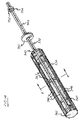
- FIG. 9 is sectional view, taken along line 2 - 2 in FIG. 1 , of the integrated condenser/receiver of FIG. 1 , wherein the desiccant cartridge includes a rigid stand-off member and a porous desiccant bag which is partially broken away to reveal a portion of the rigid stand-off member;
- FIG. 10 is a perspective view of a rigid stand-off member for the first preferred desiccant cartridge shown in FIG. 9 ;
- FIG. 11 is a sectional view of a clamp portion of the rigid stand-off member of FIGS. 9 and 10 in an open position, with the closed position suggested in phantom;
- FIG. 12 is a schematic sectional view of a portion of an improved integrated condenser/receiver in accordance with the invention.
- FIG. 13 is a perspective view of a second embodiment of a desiccant cartridge for use in a receiver such as that shown in FIG. 1 ;
- FIG. 15 is a sectional view of the desiccant cartridge of FIG. 14 , taken along the line 8 - 8 in FIG. 14 ;
- FIG. 16 is sectional view of the receiver of FIG. 1 , taken along the line 1 - 1 in FIG. 1 ;
- FIG. 18 is an exploded view of a portion of the sectional view of FIG. 16 , showing a rigid cap of the preferred desiccant cartridge of FIG. 17 ;
- FIG. 19 is a schematic sectional view of a portion of an integral condenser/receiver with the preferred desiccant cartridge positioned in the receiver of the integrated condenser/receiver.
- a receiver 10 includes a canister 12 defining a pair of bosses 14 and 16 ; a plug 18 ; and an end panel 20 .
- the canister 12 defines a reservoir 22 which communicates through an inlet port 24 extending through the boss 14 and an outlet port extending through the boss 16 .
- a preferred desiccant cartridge 30 positioned in the reservoir 22 comprises a rigid member or dongle 32 and a porous desiccant pouch or bag 34 containing a powdered or granulated desiccant material 36 .
- the preferred reservoir 22 is substantially cylindrical in shape, having an open end 27 presenting internal threads 28 .
- the preferred rigid dongle 32 includes a web portion 40 ; a cylindrical skirt portion 42 ; and a tab portion 44 extending transversely from the web portion 40 .
- the web portion 40 closes an end of the skirt portion 42 to define a cavity 46 .
- the preferred skirt portion 42 further has a pair of holes 50 and 52 extending from the cavity 46 to an exterior surface of the skirt portion 42 for use in removing the desiccant cartridge 30 ( FIG. 2 ) from the receiver 10 ( FIG. 2 ).
- the preferred tab portion 44 defines an engaging surface 60 , most preferably flat, and the dongle 32 includes a plurality of energy directors 62 extending from the engaging surface 60 .
- the end closure 18 serves to position the desiccant cartridge 30 in the reservoir 22 .
- the preferred end closure 18 includes a plug portion 70 and an elongated, cylindrical stand-off portion 72 which is relatively thin in the sense that the elongated stand-off portion 72 is thinner in cross-section than the plug portion 72 .
- the plug portion 70 presents external threads 80 for positioning and securing the plug portion 70 and at least one annular groove (two shown at 82 in FIG. 5 ) for receiving at least one annular seal (two shown at 86 in FIG. 2 ) such as O-ring seals.
- the desiccant cartridge 30 is susceptible of a relatively simple method of production.
- the preferred rigid dongle 32 is formed as a one-piece, plastic casting by means of a conventional casting process.
- the preferred porous desiccant bag 34 is manufactured from a tube (not shown) of porous polyester material or the like. Most preferably, the porous tube (not shown) is formed of point bonded nylon, specifically PBN-II available from Cerex Advanced Fabrics.
- one of the first and second flat end seals 90 , 92 is affixed to the flat engaging surface 60 ( FIG. 3 ) of the tab portion 44 of the rigid dongle 32 , most preferably by ultrasonic welding.
- the second flat end seal 92 is shown affixed to the tab portion 44 in FIG. 2 .
- the energy directors 62 FIGS. 3 and 4 ) facilitate the welding of the first or second flat end seal 90 , 92 to the tab portion 44 .
- the first or second flat end seal 90 , 92 which is to be welded to the tab portion 44 is extended away from the bulk of the porous desiccant bag 32 so as to minimize damage to the porous desiccant bag 34 during welding.
- the elongated stand-off portion 72 of the end closure 18 serves to position the desiccant cartridge 30 so that the porous desiccant bag 34 straddles the inlet and outlet ports 24 , 26 . More specifically, the preferred elongated stand-off portion 72 extends into the cavity 46 and abuts against the web portion 42 of the rigid dongle 32 . As the end closure 18 is inserted into the open end 27 of the reservoir 22 , the elongated stand-off portion 72 presses against the rigid dongle 32 to position the desiccant cartridge 30 in the reservoir 22 .
- FIG. 6 The operation of the receiver 10 ( FIG. 1 ) is illustrated in FIG. 6 .
- the receiver 10 is shown juxtaposed with a header tank 110 of a condenser (not shown) for an automotive air conditioner or the like (not shown).
- the header tank 110 is divided into a first chamber 120 and a second chamber 122 .
- a plurality of passages 124 communicate with the first chamber 120 while another plurality of passages 126 communicate with the second chamber 122 .
- the configurations of the condenser (not shown) and of the header tank 110 are not critical to the invention.
- the fluid (not shown) within the reservoir 22 enters the sides of the porous desiccant bag 34 and percolates through the desiccant material 36 ( FIG. 2 ).
- the desiccant material 36 ( FIG. 2 ) adsorbs oil, moisture and other contaminants from the refrigerant fluid (not shown) as the fluid percolates through the porous desiccant bag 34 .
- a collar or the like (not shown) around the porous desiccant bag 34 for inhibiting flow through the reservoir 22 bypassing the porous desiccant bag 34 .
- a collar (not shown) has an external annular groove (not shown) for mounting an annular seal (not shown) for sealing the portion of the reservoir 22 surrounding the porous desiccant bag.
- an annular seal (not shown) for sealing the portion of the reservoir 22 surrounding the porous desiccant bag.
- such collar (not shown) is positioned over the porous desiccant bag 34 so as to lie between the inlet port 24 and the outlet port 26 when the desiccant cartridge 30 is positioned in the reservoir 22 .
- the refrigerant fluid (not shown) exiting the porous desiccant bag 34 passes from the reservoir 22 through the outlet port 26 . From the outlet port 26 , the refrigerant fluid (not shown) proceeds to the condenser (not shown) through the plurality of passages 126 .
- the design of the desiccant cartridge 30 also facilitates the removal of the desiccant cartridge 30 from the reservoir 22 when the desiccant material 36 is spent.
- one of the holes 50 ( FIG. 4 ), 52 is engaged by a hook or the like (not shown) and then the desiccant cartridge is pulled as a unit through the open end 27 of the reservoir 22 .
- a second preferred receiver 210 for an integrated condenser/receiver includes a canister 212 defining a pair of bosses 214 and 216 ; a demountable plug or end closure 218 ; and an end panel 220 .
- the canister 212 defines a reservoir 222 which communicates with the exterior of the receiver 210 through an inlet port 224 extending through the boss 214 and an outlet port 226 extending through the boss 216 .
- the preferred reservoir 222 is substantially cylindrical in shape, having an open end 227 presenting internal threads 228 .
- a second preferred embodiment of a desiccant cartridge 230 positioned in the reservoir 222 comprises a rigid stand-off member 232 and a porous desiccant pouch or bag 234 containing a powdered or granulated desiccant material 236 .
- the preferred rigid stand-off member 232 includes a web portion or inner pad portion 240 ; an elongated, relatively thin stand-off portion 242 terminating in the web portion 240 ; and a tab portion 244 extending transversely from the web portion 240 .
- the desiccant cartridge 230 is susceptible of a relatively simple method of production.
- the preferred rigid stand-off member 232 is formed as a one-piece, plastic casting by means of a conventional casting process.
- the preferred porous desiccant bag 234 is manufactured by forming a first flat end seal 290 in a first open end (not shown) of a tube (not shown) of porous polyester felt material or the like; pouring the desiccant material (not shown) into the porous tube; and forming a second flat end seal 292 in a second open end (not shown) of the porous tube.
- a fluorescent tracer dye wafer or the like 294 FIG.
- first and second flat end seals 290 , 292 (the second flat end seal 292 in FIG. 6 ) is affixed to the tab portion 244 of the rigid stand-off member 232 .
- the first and second flat end seals 290 , 292 are preferably formed, and one of the first and second flat end seals 290 , 292 is affixed to the tab portion 244 , by ultrasonic welding, although other suitable techniques (such as thermal or vibration welding) will be apparent to those of ordinary skill in the art.
- the first or second flat end seal 290 , 292 which is to be welded to the tab portion 244 is extended away from the bulk of the porous desiccant bag 234 so as to minimize damage to the porous desiccant bag 234 during welding.
- the plug 218 and the open end 227 of the reservoir 222 present complementary threads 228 and 300 so as to allow the plug 218 to be threadedly engaged and retained in the open end 227 .
- One or more annular seals 302 such as O-rings are mounted on the plug 218 to inhibit flow between the plug 218 and the outer surface bounding the open end 227 .
- the plug 218 abuts against the rigid stand-off member 232 to retain the desiccant cartridge 230 in position in the reservoir 222 .
- the web portion 240 and the flange 248 are each of substantially the same size and shape as a cross-section of the reservoir 222 so as to promote correct positioning, and inhibit lateral motion, of the desiccant cartridge 230 in the reservoir 222 .
- the design of the desiccant cartridge 230 also facilitates the removal of the desiccant cartridge 230 from the reservoir 222 when the desiccant material 236 is spent.
- the eye 252 is engaged by a hook or the like (not shown) and then the desiccant cartridge 230 is pulled as a unit from the reservoir 222 .
- the elongated stand-off portion 242 is gripped to permit the desiccant cartridge 230 to be pulled form the reservoir 222 as a unit.
- FIGS. 9-13 illustrate another embodiment of the desiccant cartridge 130 comprising a rigid stand-off member 132 and a porous desiccant pouch or bag 134 containing a powdered or granulated desiccant material 136 .
- a preferred rigid stand-off member 132 includes an inner pad portion 140 ; an outer pad portion 142 ; an elongated stand-off portion 144 terminating in the inner pad portion 140 ; a spacing rib portion 146 eccentrically spacing the inner and outer pad portions 140 , 142 ; and a clamp portion 148 supported by the spacing rib 146 .
- the elongated stand-off portion 144 and the spacing rib portion 146 extend from opposite sides of the inner pad portion 140 in opposite directions.
- the preferred elongated stand-off portion 144 includes a flange 150 and an eye 152 surrounded by a rigid boss 154 .
- the clamp portion 148 includes a first clamping jaw 160 supported by the spacing rib portion 146 and a second clamping jaw 162 supported by the first clamping jaw 160 .
- the first and second clamping jaws 160 , 162 also cooperate to define an annular channel 164 .
- first clamping jaw 160 and the second clamping jaw 162 are separated by a partial cleft 170 which leaves thin plastic connectors 172 (only one shown) defining a living hinge between the first and second clamping jaws 160 , 162 .
- the second clamping jaw 162 is able to pivot about the thin plastic connectors 172 between an open position (shown by first and second clamping jaws 160 , 162 ) and a closed position (shown by first and second clamping jaws 160 , 162 ′).
- the first and second clamping jaws 160 , 162 mount complementary detents 180 , 182 for engagement to secure the first and second clamping jaws 160 , 162 in the closed position.
- one configuration of the complementary detents 180 , 182 includes a clasp 180 mounted by the second clamping jaw 162 and a complementary socket 182 mounted by the first clamping jaw 60 for receipt of the clasp 180 .
- the design of the complementary detents 180 , 182 is not critical to the invention and other suitable detent configurations will be apparent to those of ordinary skill in the art.
- the desiccant cartridge 130 is susceptible of a relatively simple method of production.
- the preferred rigid stand-off member 132 is formed as a one-piece, plastic casting by means of a conventional casting process.
- the preferred porous desiccant bag 134 is manufactured by forming a first flat end seal 190 in a first open end (not shown) of a tube (not shown) of porous polyester felt material or the like; pouring the desiccant material 136 into the porous tube; and forming a second flat end seal 192 in a second open end (not shown) of the porous tube.
- the porous tube (not shown) is formed of point bonded nylon, specifically PBN-II available from Cerex Advanced Fabrics.
- the first and second flat end seals 190 , 192 of the tube are formed by ultrasonic welding. Other suitable techniques (such as thermal or vibration welding) will be apparent to those of ordinary skill in the art.
- a fluorescent tracer dye wafer or the like 193 is placed in the porous desiccant bag 134 with the desiccant material 136 so that leaks in the system (not shown) in which the receiver 10 is used can be readily detected by use of an ultraviolet light source (not shown).
- the porous desiccant bag 134 is secured to the rigid stand-off member 132 .
- the first and second flat end seals 190 , 192 are secured to the inner and outer pad portions 140 , 142 by ultrasonic welding, although other suitable techniques (such as thermal or vibration welding) will be apparent to those of ordinary skill in the art.
- the clamp portion 148 is closed about a middle portion of the porous desiccant bag 134 to secure the porous desiccant bag to the spacer rib portion 146 ( FIGS. 10 and 11 ).
- the fluid (not shown) within the reservoir 22 enters the sides of the porous desiccant bag 134 and percolates through the desiccant material 136 ( FIG. 9 ).
- the desiccant material 136 ( FIG. 9 ) adsorbs oil, moisture and other contaminants from the refrigerant fluid (not shown) as the fluid percolates through the porous desiccant bag 134 .
- the design of the desiccant cartridge 130 facilitates installing and positioning the desiccant cartridge 130 into the reservoir 22 of the receiver 10 .
- the desiccant cartridge 130 is pressed as a unit through an open end 196 of the canister 112 until the outer pad portion lies near, or in abutment with, the end panel 20 .
- the elongated stand-off portion 132 serves to position the porous desiccant bag 134 so that the porous desiccant bag 134 straddles the inlet and outlet ports 24 , 26 .
- the desiccant cartridge 130 is positioned so that the clamp portion 148 lies between the inlet and outlet ports 24 , 26 .
- the annular seal 194 engages an inner surface of the canister 112 bounding the reservoir 22 so as to inhibit flow between the inlet and outlet ports 24 , 26 bypassing the porous desiccant bag 134 .
- the plug 118 abuts against the elongated stand-off member 132 to retain the desiccant cartridge 130 in position in the reservoir 22 .
- the inner pad portion 140 , the outer pad portion 142 and the flange 150 are each configured in size and shape to closely fit within the reservoir 22 so as to promote correct positioning, and inhibit lateral motion, of the desiccant cartridge 130 in the reservoir 22 .
- the design of the desiccant cartridge 130 also facilitates the removal of the desiccant cartridge 130 from the reservoir 22 when the desiccant material 136 is spent.
- the desiccant cartridge 130 from the reservoir 22 , the eye 152 is engaged by a hook or the like (not shown) and then the desiccant cartridge 130 is pulled as a unit from the reservoir 22 .
- the elongated stand-off portion 144 is gripped to permit the desiccant cartridge 130 to be pulled form the reservoir 22 as a unit.
- FIG. 13 shows another preferred embodiment of a desiccant cartridge 130 for installation in a receiver 10 of the same design as the receiver 10 in FIG. 1 and FIG. 9 .
- the desiccant cartridge 130 comprises a rigid stand-off member 132 and a porous desiccant pouch or bag 134 .
- the preferred rigid stand-off member 132 includes an inner pad portion 140 ; an elongated stand-off portion 144 terminating in the inner pad portion 140 ; and a tab portion 149 extending transversely from the inner pad portion 140 .
- the preferred elongated stand-off portion 144 includes a flange 150 which cooperates with the inner pad portion 140 to promote correct positioning, and inhibit lateral motion, of the desiccant cartridge 130 in the reservoir 22 .
- the desiccant cartridge 130 of FIG. 13 is susceptible of a relatively simple method of production.
- the preferred rigid stand-off member 132 is formed as a one-piece, plastic casting by means of a conventional casting process.
- the preferred porous desiccant bag 134 is manufactured by forming a first flat end seal 190 in a first open end (not shown) of a tube (not shown) of porous polyester felt material or the like; pouring the desiccant material (not shown) into the porous tube; and forming a second flat end seal 192 in a second open end (not shown) of the porous tube.
- a fluorescent tracer dye wafer or the like (not shown) is placed in the porous desiccant bag 134 with the desiccant material (not shown) so that leaks in the system (not shown) in which the receiver 10 ( FIG. 1 ) is used can be readily detected by use of an ultraviolet light source (not shown).
- the first and second flat end seals 190 , 192 are preferably formed, and one of the first and second flat end seals 190 , 192 is affixed to the tab portion 149 , by ultrasonic welding, although other suitable techniques (such as thermal or vibration welding) will be apparent to those of ordinary skill in the art. Most preferably, the first or second flat end seal 190 , 192 which is to be welded to the tab portion 149 is extended away from the bulk of the porous desiccant bag 134 , so as to minimize damage to the porous desiccant bag 134 during welding.
- the preferred rigid stand-off member 332 includes an inner pad portion 340 ; an outer pad portion 342 ; an elongated stand-off portion 344 terminating in the inner pad portion 340 ; and a plurality of annularly-arrayed spacer bars 346 extending between the inner and outer pad portions 340 , 342 to define, in cooperation with a plurality of hoops 347 extending transversely of the spacer bars 346 , a cage portion 348 .
- the preferred elongated stand-off portion 344 includes a flange 350 and an eye 352 surrounded by a rigid boss 354 .
- the cage portion 348 includes a first cage element 360 and a second cage element 362 .
- the first cage element 360 is supported at opposite ends of the spacer bars 346 by the inner and outer pads 340 , 342 .
- the second cage element 362 is supported by the first cage element 360 . More specifically, the first cage element 360 and the second cage element 362 are separated by partial radial clefts 370 (only one shown) through each of the hoops 347 (only one shown) which leave thin plastic connectors 372 (only one shown) defining living hinges between the first and second cage elements 360 , 362 .
- the second cage element 362 is able to pivot about the thin plastic connectors 372 between an open position (not shown) and a closed position (shown in FIG. 15 ).
- the first and second cage elements 360 , 362 mount complementary detents 380 and 382 for engagement to secure the first and second cage elements 360 , 362 in the closed position.
- one configuration of the complementary detents 380 , 382 includes a clasp 380 mounted by the second cage element 362 and a complementary socket 382 mounted by the first cage element 360 for receipt of the clasp 380 .
- the design of the complementary detents 380 , 382 is not critical to the invention and other suitable detent configurations will be apparent to those of ordinary skill in the art.
- the desiccant cartridge 330 is also susceptible of a relatively simple method of production.
- the preferred rigid stand-off member 332 is formed as a one-piece, plastic casting by means of a conventional casting process.
- the porous desiccant bag 334 preferably is manufactured in the same manner as the porous desiccant bags 34 and 134 of previous embodiments so as to leave first and second flat end seals 390 , 392 .
- One or both of the first and second flat end seals 390 , 392 are secured to the inner and outer pad portions 340 , 342 by ultrasonic welding, although other suitable techniques (such as thermal or vibration welding) will be apparent to those of ordinary skill in the art.
- the cage portion 348 is closed about the porous desiccant bag 334 , thereby immobilizing the porous desiccant bag 334 relative to the rigid stand-off member 332 to facilitate installation and removal of the desiccant cartridge 130 .
- FIG. 13 and FIGS. 14 and 15 operate in substantially the same manner as the embodiment of FIGS. 9-12 and share the same advantages of relatively simple installation and removal.
- the only extraneous material removed from the receiver 10 with any of the porous desiccant bags 134 ( FIG. 9 and FIG. 13) and 334 ( FIG. 14 ) is the rigid stand-off member 132 ( FIGS. 9-11 ), 132 ( FIG. 13 ), 332 ( FIGS. 14 and 15 ).
- each of the rigid stand-off members 132 , 332 is relatively simple in design and inexpensive to produce.
- FIGS. 16-19 another exemplary embodiment of a preferred desiccant cartridge 430 is illustrated.
- the desiccant cartridge is similar to previous embodiments in that it is positioned in the reservoir 422 and comprises a rigid stand-off member 432 and a porous desiccant pouch or bag 434 containing a powdered or granulated desiccant material 436 .
- the embodiment of FIGS. 16-19 also includes a cylindrical cap 438 .
- the cap 438 includes an annular sleeve portion 460 ; a web portion 462 closing a distal end of the annular sleeve portion 460 to define an interior cavity 464 ; and a spacer portion 466 in the form of a cylindrical spacer bar extending outwardly from the web portion 462 .
- a plurality of small holes 470 through the web portion 462 communicate between the cavity 464 and the exterior of the cap 438 .
- the annular sleeve portion 460 mounts an annular seal or collar portion 476 which extends radially outwardly from the sleeve portion 460 .
- the annular seal portion 476 is sufficiently thin to provide the annular seal portion 476 with a degree of resilient flexibility when subjected to shear forces.
- the desiccant cartridge 430 is susceptible of a relatively simple method of production.
- the preferred rigid stand-off member 432 is formed as a one-piece, plastic casting by means of a conventional casting process.
- the preferred porous desiccant bag 434 is manufactured by sealing a first open end (not shown) of a tube (not shown) of porous polyester felt material or the like; pouring the desiccant material (not shown) into the porous tube; and forming a flat end seal 480 in a second open end (not shown) of the porous tube.
- one of the flat end seal 480 is affixed to the tab portion 446 of the rigid stand-off member 432 .
- the flat end seals 480 is preferably formed and affixed to the tab portion 446 by ultrasonic welding, although other suitable techniques (such as thermal or vibration welding) will be apparent to those of ordinary skill in the art.
- FIG. 19 The operation of the receiver 10 ( FIG. 1 ) is illustrated in FIG. 19 .
- the receiver 10 is shown juxtaposed with a header tank 110 of a condenser (not shown) for an automotive air conditioner or the like (not shown).
- the header tank 110 is divided into a first chamber 120 and a second chamber 122 .
- a plurality of passages 130 communicate with the first chamber 120 while another plurality of passages 132 communicate with the second chamber 122 .
- the configurations of the condenser (not shown) and of the header tank 110 are not critical to the invention.
- the fluid (not shown) within the reservoir 422 enters the sides of the porous desiccant bag 434 and percolates through the desiccant material 436 ( FIG. 17 ).
- the desiccant material 436 ( FIG. 17 ) adsorbs oil, moisture and other contaminants from the refrigerant fluid (not shown) as the fluid percolates through the porous desiccant bag 434 .
- the annular seal 476 of the rigid cap 438 acts as a baffle to inhibit flow bypassing the porous desiccant bag 434 .
- the refrigerant fluid (not shown) flows out of the desiccant bag 434 through the plurality of holes 470 ( FIG. 18 ) through the web portion 462 ( FIG. 18 ) of the rigid cap 438 . It is desirable that the plurality of holes 470 ( FIG. 18 ) be so dimensioned as to permit the flow of refrigerant fluid (not shown) while retaining the desiccant material 436 ( FIG. 16 ) and inhibiting the flow of moisture, oil and other contaminants. In this manner, the plurality of holes 470 ( FIG. 18 ) provides additional filtering of the refrigerant fluid (not shown) which percolates through the desiccant material 436 ( FIG. 16 ) in the porous desiccant bag 434 .
- the desiccant material 436 ( FIG. 16 ) is in the form of grains defining maximum effective grain diameters; the plurality of holes 470 ( FIG. 18 ) define maximum effective hole diameters; and the maximum effective hole diameters are substantially no greater than the maximum effective grain diameters so as to retain the desiccant material 436 ( FIG. 16 ) and inhibit the flow of moisture, oil and other contaminants (not shown) through to the outlet port 26 .
- the refrigerant fluid passes from the reservoir 422 through the outlet port 26 . From the outlet port 26 , the refrigerant fluid (not shown) proceeds to the condenser (not shown) through the plurality of passages 132
- the design of the desiccant cartridge 430 facilitates installing and positioning the desiccant cartridge 430 in the reservoir 422 of the receiver 10 .
- the desiccant cartridge 430 is pressed as a unit through an open end 496 of the canister 412 until the spacer portion 466 of the cap 438 abuts against the end panel 20 .
- the spacer portion 466 of the cap 438 and the elongated stand-off portion 432 of the rigid stand-off member 432 cooperate to position the porous desiccant bag 434 so that the porous desiccant bag 434 straddles the inlet and outlet ports 24 , 26 .
- the plug 418 is inserted into the open end 496 of the reservoir 422 to seal the open end 96 .
- the plug 418 and the open end 496 of the reservoir 422 present complementary threads so as to allow the plug 418 to be threadedly engaged and retained in the open end 496 .
- One or more annular seals 100 inhibit flow between the plug 418 and the outer surface bounding the open end 496 .
- the plug 418 abuts against the elongated stand-off member 432 to retain the desiccant cartridge 430 in position in the reservoir 422 .
- the inner pad portion 440 and the flange 450 are each configured in size and shape to closely fit within the reservoir 422 so as to cooperate with the annular seal portion 476 of the cap 438 to promote correct positioning, and inhibit lateral motion, of the desiccant cartridge 430 in the reservoir 422 .
- the design of the desiccant cartridge 430 also facilitates the removal of the desiccant cartridge 430 from the reservoir 422 when the desiccant material 436 is spent.
- the desiccant cartridge 430 from the reservoir 422 , the eye 452 is engaged by a hook or the like (not shown) and then the desiccant cartridge 430 is pulled as a unit from the reservoir 422 .
- the elongated stand-off portion 442 is gripped to permit the desiccant cartridge 430 to be pulled form the reservoir 422 as a unit.
- the rigid stand-off member 432 and the rigid cap 438 are relatively simple in design and inexpensive to produce. Thus, it is highly economic to either discard the desiccant cartridge 430 as a unit or to destroy the desiccant cartridge 430 to recover the desiccant material 436 for either regeneration or separate disposal.
Landscapes
- Engineering & Computer Science (AREA)
- Chemical & Material Sciences (AREA)
- Analytical Chemistry (AREA)
- General Chemical & Material Sciences (AREA)
- Oil, Petroleum & Natural Gas (AREA)
- Chemical Kinetics & Catalysis (AREA)
- Physics & Mathematics (AREA)
- Mechanical Engineering (AREA)
- Thermal Sciences (AREA)
- General Engineering & Computer Science (AREA)
- Power Engineering (AREA)
- Drying Of Gases (AREA)
Abstract
Description
Claims (54)
Priority Applications (1)
| Application Number | Priority Date | Filing Date | Title |
|---|---|---|---|
| US10/511,356 US7275390B2 (en) | 2002-04-17 | 2003-04-15 | Desiccant cartridge for an integrated condenser/receiver and method of making same |
Applications Claiming Priority (5)
| Application Number | Priority Date | Filing Date | Title |
|---|---|---|---|
| US37338602P | 2002-04-17 | 2002-04-17 | |
| US37318502P | 2002-04-17 | 2002-04-17 | |
| US37468902P | 2002-04-23 | 2002-04-23 | |
| PCT/US2003/011736 WO2003089852A1 (en) | 2002-04-17 | 2003-04-15 | Desiccant cartridge for an integrated condenser/receiver and method of making same |
| US10/511,356 US7275390B2 (en) | 2002-04-17 | 2003-04-15 | Desiccant cartridge for an integrated condenser/receiver and method of making same |
Publications (2)
| Publication Number | Publication Date |
|---|---|
| US20050229628A1 US20050229628A1 (en) | 2005-10-20 |
| US7275390B2 true US7275390B2 (en) | 2007-10-02 |
Family
ID=29255344
Family Applications (1)
| Application Number | Title | Priority Date | Filing Date |
|---|---|---|---|
| US10/511,356 Expired - Fee Related US7275390B2 (en) | 2002-04-17 | 2003-04-15 | Desiccant cartridge for an integrated condenser/receiver and method of making same |
Country Status (4)
| Country | Link |
|---|---|
| US (1) | US7275390B2 (en) |
| EP (1) | EP1497596B1 (en) |
| DE (1) | DE60332825D1 (en) |
| WO (1) | WO2003089852A1 (en) |
Cited By (2)
| Publication number | Priority date | Publication date | Assignee | Title |
|---|---|---|---|---|
| US20120060546A1 (en) * | 2010-09-10 | 2012-03-15 | Visteon Global Technologies, Inc. | Receiver dryer |
| US20150292811A1 (en) * | 2011-06-08 | 2015-10-15 | Ail Research Inc. | Heat and mass exchangers having extruded plates |
Families Citing this family (10)
| Publication number | Priority date | Publication date | Assignee | Title |
|---|---|---|---|---|
| US6763679B1 (en) * | 2003-04-01 | 2004-07-20 | Delphi Technologies, Inc. | Standoff for desiccant in condenser reservoir of automotive air conditioning system |
| EP1574795A1 (en) * | 2004-03-09 | 2005-09-14 | Delphi Technologies, Inc. | Receiver for air conditioning |
| FR2872261B1 (en) * | 2004-06-29 | 2006-08-25 | Valeo Thermique Moteur Sas | IMPROVED TANK FOR A HEAT EXCHANGER, FOR EXAMPLE A CLIMATE CONTROL CONDENSER |
| WO2007133447A1 (en) | 2006-05-09 | 2007-11-22 | Flow Dry Technology, Inc. | Desiccant bag and filter assembly |
| USD558319S1 (en) * | 2006-11-01 | 2007-12-25 | Idea International Co., Ltd. | Humidifier |
| US20080229605A1 (en) * | 2007-03-23 | 2008-09-25 | Brown Jerome R | Gas drying assembly with cartridge and method |
| JP6696175B2 (en) * | 2015-12-28 | 2020-05-20 | ユニオン昭和株式会社 | Capacitor |
| CN108895729B (en) * | 2018-08-13 | 2024-08-02 | 浙江新昌同一汽车部件有限公司 | Connection structure of automobile condenser and liquid storage tank |
| USD903071S1 (en) * | 2018-09-17 | 2020-11-24 | Mi Rea Seo | Condenser for vehicles |
| US11692751B2 (en) | 2020-06-04 | 2023-07-04 | Denso International America, Inc. | Desiccant bag spacer and cage |
Citations (17)
| Publication number | Priority date | Publication date | Assignee | Title |
|---|---|---|---|---|
| US2557557A (en) | 1948-03-23 | 1951-06-19 | Remco Inc | Refrigerant drier-filter unit |
| EP0179186A2 (en) | 1984-10-26 | 1986-04-30 | ELTRO GmbH Gesellschaft für Strahlungstechnik | Harmonizing device for the lines of sight of two observation appliances |
| US5149453A (en) | 1985-02-25 | 1992-09-22 | H. B. Fuller Automotive Products, Inc. | Method for detecting leakage in a refrigeration system |
| US5215660A (en) | 1992-01-29 | 1993-06-01 | Parker Hannifin Corporation | Filter drier for refrigeration system |
| US5440910A (en) | 1993-06-07 | 1995-08-15 | Florian; David W. | Key adaptor |
| US5537839A (en) | 1992-11-18 | 1996-07-23 | Behr Gmbh & Co. | Condenser with refrigerant drier |
| US5666791A (en) | 1994-06-22 | 1997-09-16 | Behr Gmbh & Co. | Vehicle air conditioner condenser insert |
| US5718743A (en) | 1996-02-26 | 1998-02-17 | Multisorb Technologies, Inc. | Desiccant cartridge |
| US5813249A (en) | 1995-07-18 | 1998-09-29 | Denso Corporation | Refrigeration cycle |
| EP0921022A2 (en) | 1997-12-05 | 1999-06-09 | Deutsche Controls GmbH | Dryer cartridge for a vehicle air conditioning unit |
| JPH11257804A (en) | 1998-03-12 | 1999-09-24 | Zexel:Kk | Filter member for receiver tank |
| US6106596A (en) * | 1996-07-31 | 2000-08-22 | Parker-Hannifin Corporation | Receiver/dryer and method of assembly |
| US6170287B1 (en) | 1999-08-27 | 2001-01-09 | Delphi Technologies, Inc. | Desiccant installation for refrigerant condenser with integral receiver |
| US6185959B1 (en) * | 1999-04-09 | 2001-02-13 | Eaton Corporation | Refrigerant system components with cartridge type thermal expansion valve and method of making same |
| US20010025511A1 (en) | 2000-03-09 | 2001-10-04 | Michele Bernini | Filter cartridge and condenser |
| US6360560B1 (en) | 1999-12-01 | 2002-03-26 | Visteon Global Technologies, Inc. | Condenser with integral receiver dryer |
| US6474098B2 (en) | 2000-01-28 | 2002-11-05 | Stanhope Products Company | Integrated condenser-receiver desiccant bag and associated filter cap |
-
2003
- 2003-04-15 US US10/511,356 patent/US7275390B2/en not_active Expired - Fee Related
- 2003-04-15 EP EP03747006A patent/EP1497596B1/en not_active Expired - Lifetime
- 2003-04-15 DE DE60332825T patent/DE60332825D1/en not_active Expired - Lifetime
- 2003-04-15 WO PCT/US2003/011736 patent/WO2003089852A1/en not_active Ceased
Patent Citations (18)
| Publication number | Priority date | Publication date | Assignee | Title |
|---|---|---|---|---|
| US2557557A (en) | 1948-03-23 | 1951-06-19 | Remco Inc | Refrigerant drier-filter unit |
| EP0179186A2 (en) | 1984-10-26 | 1986-04-30 | ELTRO GmbH Gesellschaft für Strahlungstechnik | Harmonizing device for the lines of sight of two observation appliances |
| US5149453A (en) | 1985-02-25 | 1992-09-22 | H. B. Fuller Automotive Products, Inc. | Method for detecting leakage in a refrigeration system |
| US5215660A (en) | 1992-01-29 | 1993-06-01 | Parker Hannifin Corporation | Filter drier for refrigeration system |
| US5537839A (en) | 1992-11-18 | 1996-07-23 | Behr Gmbh & Co. | Condenser with refrigerant drier |
| US5440910A (en) | 1993-06-07 | 1995-08-15 | Florian; David W. | Key adaptor |
| US5666791A (en) | 1994-06-22 | 1997-09-16 | Behr Gmbh & Co. | Vehicle air conditioner condenser insert |
| EP0689014B1 (en) | 1994-06-22 | 1998-10-07 | Behr GmbH & Co. | Insert for the condenser of an air conditionning system of a vehicle |
| US5813249A (en) | 1995-07-18 | 1998-09-29 | Denso Corporation | Refrigeration cycle |
| US5718743A (en) | 1996-02-26 | 1998-02-17 | Multisorb Technologies, Inc. | Desiccant cartridge |
| US6106596A (en) * | 1996-07-31 | 2000-08-22 | Parker-Hannifin Corporation | Receiver/dryer and method of assembly |
| EP0921022A2 (en) | 1997-12-05 | 1999-06-09 | Deutsche Controls GmbH | Dryer cartridge for a vehicle air conditioning unit |
| JPH11257804A (en) | 1998-03-12 | 1999-09-24 | Zexel:Kk | Filter member for receiver tank |
| US6185959B1 (en) * | 1999-04-09 | 2001-02-13 | Eaton Corporation | Refrigerant system components with cartridge type thermal expansion valve and method of making same |
| US6170287B1 (en) | 1999-08-27 | 2001-01-09 | Delphi Technologies, Inc. | Desiccant installation for refrigerant condenser with integral receiver |
| US6360560B1 (en) | 1999-12-01 | 2002-03-26 | Visteon Global Technologies, Inc. | Condenser with integral receiver dryer |
| US6474098B2 (en) | 2000-01-28 | 2002-11-05 | Stanhope Products Company | Integrated condenser-receiver desiccant bag and associated filter cap |
| US20010025511A1 (en) | 2000-03-09 | 2001-10-04 | Michele Bernini | Filter cartridge and condenser |
Cited By (4)
| Publication number | Priority date | Publication date | Assignee | Title |
|---|---|---|---|---|
| US20120060546A1 (en) * | 2010-09-10 | 2012-03-15 | Visteon Global Technologies, Inc. | Receiver dryer |
| US8959948B2 (en) * | 2010-09-10 | 2015-02-24 | Halla Visteon Climate Control Corporation | Receiver dryer |
| US20150292811A1 (en) * | 2011-06-08 | 2015-10-15 | Ail Research Inc. | Heat and mass exchangers having extruded plates |
| US9389025B2 (en) * | 2011-06-08 | 2016-07-12 | Ail Research Inc. | Heat and mass exchangers having extruded plates |
Also Published As
| Publication number | Publication date |
|---|---|
| EP1497596A4 (en) | 2006-11-02 |
| WO2003089852A1 (en) | 2003-10-30 |
| DE60332825D1 (en) | 2010-07-15 |
| EP1497596A1 (en) | 2005-01-19 |
| US20050229628A1 (en) | 2005-10-20 |
| EP1497596B1 (en) | 2010-06-02 |
Similar Documents
| Publication | Publication Date | Title |
|---|---|---|
| US7275390B2 (en) | Desiccant cartridge for an integrated condenser/receiver and method of making same | |
| JP3629819B2 (en) | Condenser with integrated receiver | |
| JP4190668B2 (en) | Receiver | |
| US6474098B2 (en) | Integrated condenser-receiver desiccant bag and associated filter cap | |
| US6481241B1 (en) | Accumulator desiccant bag and method of assembling | |
| EP2016351B1 (en) | Desiccant bag and filter assembly | |
| KR100770437B1 (en) | Receiver drier with bottom inlet | |
| US20020174676A1 (en) | Self-retaining elongated adsorbent unit | |
| US6125651A (en) | Air-conditioning system accumulator and method of making same | |
| US6579351B2 (en) | Integrated filter and adsorbent unit for an integrated receiver-dryer and related method of manufacturing | |
| JP4116286B2 (en) | Receiver dryer | |
| JP2001263869A (en) | Liquid tank | |
| US7275392B2 (en) | Internal cage tube bag | |
| KR100976130B1 (en) | Heat exchanger provided with a receiver dryer, and its manufacturing method | |
| EP1477750A1 (en) | Filter desiccant unit for a condenser with a receiver canister | |
| KR20030030501A (en) | Receiver drier of a heat exchanger | |
| JP3550284B2 (en) | Gas-liquid separator for car air conditioners | |
| JPH10318631A (en) | Manufacturing method for liquid receiver | |
| JP2003106709A (en) | Heat exchanger | |
| EP1342965B1 (en) | Integrated condenser-receiver desiccant bag and associated filter cap | |
| KR100483107B1 (en) | Receiver / dryer and assembly method | |
| JP2003106792A (en) | Heat exchanger | |
| JPH0564674U (en) | Liquid tank | |
| HK1058700B (en) | Integrated condenser-receiver desiccant bag and associated filter cap |
Legal Events
| Date | Code | Title | Description |
|---|---|---|---|
| AS | Assignment |
Owner name: FLOW DRY TECHNOLOGY LTD., OHIO Free format text: ASSIGNMENT OF ASSIGNORS INTEREST;ASSIGNORS:EVANS, JOHN M.;FLAUGHER, DAVID V.;LECONEY, DOUGLAS E.;AND OTHERS;REEL/FRAME:016577/0982 Effective date: 20041004 |
|
| AS | Assignment |
Owner name: FLOW DRY TECHNOLOGY, INC., DISTRICT OF COLUMBIA Free format text: ASSIGNMENT OF ASSIGNORS INTEREST;ASSIGNOR:FLOW DRY TECHNOLOGY LTD;REEL/FRAME:019055/0084 Effective date: 20070306 |
|
| STCF | Information on status: patent grant |
Free format text: PATENTED CASE |
|
| FPAY | Fee payment |
Year of fee payment: 4 |
|
| AS | Assignment |
Owner name: FIRST NIAGARA BANK, N.A., PENNSYLVANIA Free format text: SECURITY INTEREST;ASSIGNOR:FLOW DRY TECHNOLOGY, INC.;REEL/FRAME:033884/0719 Effective date: 20140930 |
|
| FPAY | Fee payment |
Year of fee payment: 8 |
|
| FEPP | Fee payment procedure |
Free format text: MAINTENANCE FEE REMINDER MAILED (ORIGINAL EVENT CODE: REM.); ENTITY STATUS OF PATENT OWNER: LARGE ENTITY |
|
| LAPS | Lapse for failure to pay maintenance fees |
Free format text: PATENT EXPIRED FOR FAILURE TO PAY MAINTENANCE FEES (ORIGINAL EVENT CODE: EXP.); ENTITY STATUS OF PATENT OWNER: LARGE ENTITY |
|
| STCH | Information on status: patent discontinuation |
Free format text: PATENT EXPIRED DUE TO NONPAYMENT OF MAINTENANCE FEES UNDER 37 CFR 1.362 |
|
| AS | Assignment |
Owner name: FLOW DRY TECHNOLOGY INC, OHIO Free format text: SECURITY INTEREST;ASSIGNOR:KEYBANK NATIONAL ASSOCIATION;REEL/FRAME:050991/0674 Effective date: 20191112 |
|
| FP | Expired due to failure to pay maintenance fee |
Effective date: 20191002 |