US7224355B2 - Method for post-processing a 3D digital video signal - Google Patents
Method for post-processing a 3D digital video signal Download PDFInfo
- Publication number
- US7224355B2 US7224355B2 US10/531,935 US53193505A US7224355B2 US 7224355 B2 US7224355 B2 US 7224355B2 US 53193505 A US53193505 A US 53193505A US 7224355 B2 US7224355 B2 US 7224355B2
- Authority
- US
- United States
- Prior art keywords
- disparity map
- video signal
- projected
- digital video
- post
- Prior art date
- Legal status (The legal status is an assumption and is not a legal conclusion. Google has not performed a legal analysis and makes no representation as to the accuracy of the status listed.)
- Expired - Fee Related, expires
Links
Images


Classifications
-
- H—ELECTRICITY
- H04—ELECTRIC COMMUNICATION TECHNIQUE
- H04N—PICTORIAL COMMUNICATION, e.g. TELEVISION
- H04N13/00—Stereoscopic video systems; Multi-view video systems; Details thereof
-
- H—ELECTRICITY
- H04—ELECTRIC COMMUNICATION TECHNIQUE
- H04N—PICTORIAL COMMUNICATION, e.g. TELEVISION
- H04N19/00—Methods or arrangements for coding, decoding, compressing or decompressing digital video signals
- H04N19/50—Methods or arrangements for coding, decoding, compressing or decompressing digital video signals using predictive coding
- H04N19/597—Methods or arrangements for coding, decoding, compressing or decompressing digital video signals using predictive coding specially adapted for multi-view video sequence encoding
-
- G—PHYSICS
- G06—COMPUTING OR CALCULATING; COUNTING
- G06T—IMAGE DATA PROCESSING OR GENERATION, IN GENERAL
- G06T7/00—Image analysis
- G06T7/50—Depth or shape recovery
- G06T7/55—Depth or shape recovery from multiple images
-
- G—PHYSICS
- G06—COMPUTING OR CALCULATING; COUNTING
- G06T—IMAGE DATA PROCESSING OR GENERATION, IN GENERAL
- G06T7/00—Image analysis
- G06T7/50—Depth or shape recovery
- G06T7/55—Depth or shape recovery from multiple images
- G06T7/593—Depth or shape recovery from multiple images from stereo images
-
- H—ELECTRICITY
- H04—ELECTRIC COMMUNICATION TECHNIQUE
- H04N—PICTORIAL COMMUNICATION, e.g. TELEVISION
- H04N13/00—Stereoscopic video systems; Multi-view video systems; Details thereof
- H04N13/10—Processing, recording or transmission of stereoscopic or multi-view image signals
-
- H—ELECTRICITY
- H04—ELECTRIC COMMUNICATION TECHNIQUE
- H04N—PICTORIAL COMMUNICATION, e.g. TELEVISION
- H04N13/00—Stereoscopic video systems; Multi-view video systems; Details thereof
- H04N13/10—Processing, recording or transmission of stereoscopic or multi-view image signals
- H04N13/106—Processing image signals
- H04N13/111—Transformation of image signals corresponding to virtual viewpoints, e.g. spatial image interpolation
-
- H—ELECTRICITY
- H04—ELECTRIC COMMUNICATION TECHNIQUE
- H04N—PICTORIAL COMMUNICATION, e.g. TELEVISION
- H04N13/00—Stereoscopic video systems; Multi-view video systems; Details thereof
- H04N13/10—Processing, recording or transmission of stereoscopic or multi-view image signals
- H04N13/106—Processing image signals
- H04N13/122—Improving the 3D impression of stereoscopic images by modifying image signal contents, e.g. by filtering or adding monoscopic depth cues
-
- H—ELECTRICITY
- H04—ELECTRIC COMMUNICATION TECHNIQUE
- H04N—PICTORIAL COMMUNICATION, e.g. TELEVISION
- H04N13/00—Stereoscopic video systems; Multi-view video systems; Details thereof
- H04N13/10—Processing, recording or transmission of stereoscopic or multi-view image signals
- H04N13/106—Processing image signals
- H04N13/128—Adjusting depth or disparity
-
- G—PHYSICS
- G06—COMPUTING OR CALCULATING; COUNTING
- G06T—IMAGE DATA PROCESSING OR GENERATION, IN GENERAL
- G06T2200/00—Indexing scheme for image data processing or generation, in general
- G06T2200/04—Indexing scheme for image data processing or generation, in general involving 3D image data
Definitions
- the present invention relates to a method for post-processing a digital video signal, said digital video signal having a plurality of views with associated disparity maps.
- Such a method may be used in, for example, a video communication system for 3D video applications within MPEG standards.
- 3D scenes rely on depth maps and disparity maps.
- the depth map of a point of view is a grayscale image, each pixel of which contains the distance to a camera filming the scene.
- Reconstruction the new point of view created being called a Reconstructed view (or reconstructed image). If a point P of the scene is visible from both points of view, a translation vector will give its pixel coordinate in the new point of view from its pixel coordinate in the original one. These vectors are called disparity vectors. Projective geometry results, as disclosed in the document “three dimensional computer vision—O. Faugeras MIT Press 1993”, establish a simple relation between disparity vectors of the disparity map and depth values of the depth map.
- multi-view or stereo coding schemes During transmission of a video signal, multi-view or stereo coding schemes, well known to those skilled in the art, generally encode by compression the textures and the depth maps needed to cover a certain range of points of view.
- texture can be encoded by using standard methods, potentially leading to well-known artifacts in the case of lossy encoding
- depth (or disparity) encoding is a little more tricky: for an encoded depth map to have a visually similar aspect as the original one does not necessarily mean that it has the same reconstruction properties.
- points or areas could be translated to the wrong place (because of wrong disparity vectors). This would create texture discontinuities that may be more noticeable than what the “visual” aspect of the encoded map suggested.
- depth map can be encoded using the Multiple Auxiliary Component tools (MAC) (as described in ⁇ Amendment 1: Visual extensions, ISO/IEC JTC 1/SC 29/WG 11 N 3056, December 1999>>), in which they are DCT encoded on a block basis, similarly to a classic luminance image encoding well known to those skilled in the art.
- MAC Multiple Auxiliary Component tools
- No specific treatments of the underlying artifacts are proposed but traditional MPEG tools that, as previously stated, are good for texture but not necessarily for depth maps.
- this can lead to a fuzzy edge along with isolated texture pixels, two effects that, moreover, are time-inconsistent in the course of following points of view.
- An embodiment of the method according to the invention comprises the steps defined in claim 2 .
- a further embodiment of the method according to the invention comprises the steps defined in claim 3 .
- a further embodiment of the method according to the invention comprises the steps defined in claim 4 .
- a further embodiment of the method according to the invention comprises the steps defined in claim 5 .
- a further embodiment of the method according to the invention comprises the steps defined in claim 6 .
- a further embodiment of the method according to the invention comprises the steps defined in claim 7 .
- FIG. 1 is a schematic diagram of the method for post-processing a video signal according to the invention
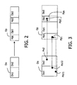
- FIG. 2 depicts some holes in a projected disparity map, holes generated by the first step of the method for post-processing a video signal of FIG. 1 ;
- FIG. 3 depicts the filtering of holes in the projected disparity map during a first step of the method for post-processing a video signal of FIG. 1 ,
- FIG. 4 illustrates the filling of holes in the projected disparity map during a second step of the method for post-processing a video signal of FIG. 1 .
- FIG. 5 illustrates the filtering of undefined pixel values during the third step of the method for post-processing a video signal of FIG. 1 .
- the present invention relates to a method for post-processing a digital video signal.
- Such a method may be used within a video communication system for 3D video applications in MPEG4.
- a 3D video signal comprises a plurality of points of view with different associated characteristics such as shape, texture, motion vectors, disparity map, depth map, colors, etc.
- a video signal When a video signal is transmitted, it is encoded. During the encoding process, its different characteristics are encoded and especially the disparity and depth maps with a compression algorithm. This compression may lead to impaired disparity and depth maps with artifacts.
- the post-processing method is based on the fact that, during the reconstruction of a new view from another view and its impaired depth map, the depth map, as described further, undergoes some transformation (for example projection), making it easier to detect problematic values than when using the original decoded map.
- some transformation for example projection
- disparity maps Since it is always possible to have disparity vectors that are all along the same direction—by rectification of the original stereo pair according to epipolar constraints for example, well-known to those skilled in the art and described in the document “O. Faugeras, Three-dimensional computer vision, MIT Press, 1993”, we will illustrate the method with the horizontal disparity vectors (the common case of a “parallel stereo setting” of video cameras). Of course, this should be in no way restrictive. In this case, disparity vectors are defined by a single value. Therefore, we will further refer to them as “disparity values”.
- I O will be the original texture image and IN the new reconstructed view.
- d will be the disparity map and d(x,y) will be the disparity value at pixel (x,y).
- the fact that the new view lies on the left side or on the right side of the original view and with a certain baseline (more or less far from the original view) is expressed by the a coefficient.
- I O ( x,y ) I N ( x+ ⁇ .d ( x,y ), y )
- the reconstruction process can be done in several ways, a common one of which (as described in the document “Disparity field and depth map coding for multi-view 3D image generation, by D. Tzovaras, N. Grammalidis, G. Strinzis, Signal Processing:Image Communication 11 (1998) pages 205–230)), can be divided into the following main steps that will be detailed hereinafter:
- the post-processing of a point of view is done as follows and is illustrated by FIG. 1 .
- a projected disparity map is generated from the original disparity map of a point of view. N pixels of a view are projected on one pixel of the future view. N can take any value:
- a list of disparity values corresponds to this pixel of the future view.
- the set of the lists corresponding to every pixel of the reconstructed view is the projected disparity map.
- the projected disparity map should have more or less the same regularity as the original one. It also means that, if the original disparity map has some irregularities, the projected disparity map will have the same irregularities.
- pixels could be erroneously projected on these holes areas. They are called isolated pixels.
- the method for post-processing removes those isolated projected pixels by using a first filtering F 1 .
- the filtering is performed as follows. For each pixel Pp of the projected disparity map Dp, the number of surrounding pixels Pps defined as holes is counted (the notion of “surrounding pixel” is application dependent: it may be a square neighborhood centered on the pixel, a circular, rectangular one . . . ). If this number goes beyond a certain threshold T 1 , for example more than half the number of pixels contained in the neighborhood, the considered isolated pixel is set as “hole” and any pixel of the original disparity map leading to this pixel is marked as “wrong disparity value”.
- a first wrong pixel Po 2 of the original disparity map Do has a corresponding isolated projected pixel Pp 2 on the area Dp 2 of the projected disparity map Dp.
- a second Po 11 and a third Po 12 pixel of the original disparity map Do has the same corresponding isolated projected pixel Pp 1 on the area Dp 1 of the projected disparity map Dp.
- the window in dotted line defines the surrounding pixels Pps of Pp 2 , here defined as holes, which makes Pp 2 an isolated pixel. The same holds for Pp 1 .
- pixels of the original disparity map Do corresponding to Pp 1 and Pp 2 and Po 11 and Po 12 , and Po 2 are set as “wrong value”.
- the filtering is done as follows. It is also possible to detect erroneous values by checking other isolated pixels of the projected map, as far as the number of projected pixel values is concerned.
- the isolated projected pixels are those that have no coherent characteristics with the ones of their surrounding pixels.
- the number of values of a pixel of the projected disparity map ranges between 0 and n (n depends on the original disparity map).
- the required precision in isolated pixels detection will determine which kind of isolated pixel one wants to process: the isolated pixels surrounded by holes, then the ones having two or more values, and which are surrounded by pixels containing only one value, and so on.
- a second step 2) there is a filling of the holes of the projected disparity map.
- the second step following projected disparity map generation, consists in filling the holes of this disparity map through interpolation.
- the interpolation type is selected by considering that, in the final reconstructed view, the holes correspond to something belonging to the background rather than to the foreground object (which is the most common case in “real life”). An example is given below.
- the projected disparity domain we repeat the hole-boundary disparity value over the entire line of the hole, through a padding process.
- the padding process consists in taking the boundary disparity value, which is the nearest of the hole and pads the entire line of said hole with it.
- interpolation strongly depends on hole boundary disparity values.
- the problem when using compressed (i.e. impaired) disparity maps is that the hole boundary values used for this padding process might be significantly changed by the compression algorithm and therefore might be erroneous, moreover in a way that varies from one line to the other: then, the padding process is performed on the basis of these erroneous values, which are propagated over the entire line in the hole. Visually, it can create what we call “worn edges” in the reconstructed view.
- a new specific post-processing filter F 2 for hole boundary values is applied, which avoids the problems stated above. It applies to the boundaries of a hole and not the hole itself.
- filtering is performed only at boundaries of holes that are larger than a given (application-dependent) threshold T 2 , for example, 3 pixels.
- the projected disparity map Dp comprises two areas; one filed with pixels P and the other with holes H.
- the hole H 1 is selected in the projected disparity map Dp.
- a window W of pixel values (which are not holes) is taken around the boundary pixel value Vk 1 of the considered hole H 1 . Once all the pixel values within the window W are sorted, the median value is taken and replaces the boundary pixel value Vk 1 .
- the regular padding process is performed on the hole H 1 itself with the new pixel value Vk 1 .
- a boundary pixel of a selected hole in the projected disparity map Dp is the pixel number 11 with a value 10 .
- the corresponding pixel in the original disparity map D 0 is a pixel number 1 with the value 10 .
- its new value is 5 .
- the corresponding pixel number 1 in the original disparity map Do takes the value “wrong”.
- the pixel of the original disparity map Do that, if assigned the new value 5 would have been projected to the boundary pixel number 11 , is assigned the new value 5 .
- the pixel number 6 in the original disparity map Do is assigned the value 5 .
- final regularization is preferably performed. It consists in regularization of the projected disparity map by a median filtering F 3 over the lines (this enables the projected disparity to be more regular and to smooth the irregularities that could not be detected by the previous filtering, for example because they were not located in the vicinity of big disparity discontinuities). As before, possible changes are translated to the original disparity map.
- a fourth step 4 final I N view generation based on the hole-filled projected disparity map is performed.
- the final reconstructed view R_VIEW can be generated from this filtered projected disparity map as is well known to the person skilled in the art as described in the document “Disparity field and depth map coding for multi-view 3D image generation, by D. Tzovaras, N. Grammalidis, G. Strinzis, Signal Processing:Image Communication 11 (1998) pages 205–230”.
- the reconstructed view is generated from a modified version of the original disparity map as described below.
- the original decoded disparity map with the undefined values i.e. the modified original disparity map
- one of the boundary pixel values of the undefined values is copied: in general, there are two possible boundary pixel value candidates to choose from, one on the left and one on the right of the pixel containing the undefined value.
- One choice would be to use a bilinear or nearest neighbor interpolation, but the variable size of the holes could make the interpolation inconsistent in space.
- the boundary pixel that has the closest value to the original pixel in the original decoded disparity map is preferably chosen.
- the original decoded disparity map Dco and the modified original decoded disparity map Dcco with the undefined values one can see one undefined value WV1 that has to be corrected. It corresponds to a pixel Pco 1 in the original decoded disparity map Dco.
- Ps 1 is the pixel that has the nearest value from the corresponding original pixel Pco 1 of the original decoded disparity map Dco. Said pixel Ps 1 replaces the undefined value WV1.
- the present invention is not limited to the aforementioned video application. It can be used within any application using a system for processing a signal taking compressed disparity maps into account.
- the invention applies to video compression algorithms of the other MPEG standard family (MPEG-1, MPEG-2) and to the ITU H26X family (H261, H263 and extensions, H261 being the latest today, reference number Q15-K-59) if applied to disparity map coding.
- Said hardware or software items can be implemented in several manners, such as by means of wired electronic circuits or by means of an integrated circuit that is suitably programmed.
- the integrated circuit can be contained in a computer or in a decoder.
- the decoder comprises means for performing steps 1, 2, 3 and 4 of the method for post-processing a video signal, as described previously, said means being hardware or software items as stated above.
- the integrated circuit comprises a set of instructions.
- said set of instructions contained, for example, in a computer programming memory or in a decoder memory may cause the computer or the decoder to carry out the different steps of the post-processing method.
- the set of instructions may be loaded into the programming memory by reading a data carrier such as, for example, a disk.
- a service provider can also make the set of instructions available via a communication network such as, for example, the Internet.
Landscapes
- Engineering & Computer Science (AREA)
- Multimedia (AREA)
- Signal Processing (AREA)
- Computer Vision & Pattern Recognition (AREA)
- Physics & Mathematics (AREA)
- General Physics & Mathematics (AREA)
- Theoretical Computer Science (AREA)
- Compression Or Coding Systems Of Tv Signals (AREA)
- Image Processing (AREA)
- Testing, Inspecting, Measuring Of Stereoscopic Televisions And Televisions (AREA)
Applications Claiming Priority (3)
| Application Number | Priority Date | Filing Date | Title |
|---|---|---|---|
| EP02292623 | 2002-10-23 | ||
| EP02292623.2 | 2002-10-23 | ||
| PCT/IB2003/004363 WO2004039086A2 (en) | 2002-10-23 | 2003-10-01 | Method for post-processing a 3d digital video signal |
Publications (2)
| Publication Number | Publication Date |
|---|---|
| US20060082575A1 US20060082575A1 (en) | 2006-04-20 |
| US7224355B2 true US7224355B2 (en) | 2007-05-29 |
Family
ID=32116329
Family Applications (1)
| Application Number | Title | Priority Date | Filing Date |
|---|---|---|---|
| US10/531,935 Expired - Fee Related US7224355B2 (en) | 2002-10-23 | 2003-10-01 | Method for post-processing a 3D digital video signal |
Country Status (7)
| Country | Link |
|---|---|
| US (1) | US7224355B2 (enExample) |
| EP (1) | EP1574079B1 (enExample) |
| JP (1) | JP4485951B2 (enExample) |
| KR (1) | KR100960294B1 (enExample) |
| CN (1) | CN100584039C (enExample) |
| AU (1) | AU2003263557A1 (enExample) |
| WO (1) | WO2004039086A2 (enExample) |
Cited By (10)
| Publication number | Priority date | Publication date | Assignee | Title |
|---|---|---|---|---|
| US20070296721A1 (en) * | 2004-11-08 | 2007-12-27 | Electronics And Telecommunications Research Institute | Apparatus and Method for Producting Multi-View Contents |
| US20090003728A1 (en) * | 2005-01-12 | 2009-01-01 | Koninklijke Philips Electronics, N.V. | Depth Perception |
| US20090015662A1 (en) * | 2007-07-13 | 2009-01-15 | Samsung Electronics Co., Ltd. | Method and apparatus for encoding and decoding stereoscopic image format including both information of base view image and information of additional view image |
| US20100053310A1 (en) * | 2008-08-31 | 2010-03-04 | Maxson Brian D | Transforming 3d video content to match viewer position |
| US20120162193A1 (en) * | 2010-12-22 | 2012-06-28 | Sony Corporation | Method and apparatus for multiview image generation using depth map information |
| US20130038600A1 (en) * | 2011-08-12 | 2013-02-14 | Himax Technologies Limited | System and Method of Processing 3D Stereoscopic Image |
| US20140023289A1 (en) * | 2012-07-20 | 2014-01-23 | Samsung Electronics Co., Ltd. | Apparatus and method for filling hole area of image |
| RU2535183C1 (ru) * | 2013-07-25 | 2014-12-10 | Федеральное государственное бюджетное образовательное учреждение высшего профессионального образования "Южно-Российский государственный университет экономики и сервиса" (ФГБОУ ВПО "ЮРГУЭС") | Устройство предобработки карты глубины стереоизображения |
| US9076249B2 (en) * | 2012-05-31 | 2015-07-07 | Industrial Technology Research Institute | Hole filling method for multi-view disparity maps |
| US11535545B2 (en) | 2020-02-07 | 2022-12-27 | Mcfadden Engineering, Inc. | Anaerobic and aerobic treatment system and process for landfill wastewater |
Families Citing this family (30)
| Publication number | Priority date | Publication date | Assignee | Title |
|---|---|---|---|---|
| WO2005107143A1 (en) * | 2004-04-30 | 2005-11-10 | Research In Motion Limited | System and method for administering digital certificate checking |
| KR101244911B1 (ko) * | 2005-10-11 | 2013-03-18 | 삼성전자주식회사 | 카메라 파라미터를 이용한 다시점 동영상 부호화 및 복호화장치 및 방법과 이를 수행하기 위한 프로그램이 기록된기록매체 |
| MY159176A (en) * | 2005-10-19 | 2016-12-30 | Thomson Licensing | Multi-view video coding using scalable video coding |
| JP2009515404A (ja) | 2005-11-04 | 2009-04-09 | コーニンクレッカ フィリップス エレクトロニクス エヌ ヴィ | マルチビューディスプレイのための画像データの再生 |
| CN101322418B (zh) * | 2005-12-02 | 2010-09-01 | 皇家飞利浦电子股份有限公司 | 图像信号的深度相关的滤波 |
| KR100747598B1 (ko) * | 2005-12-09 | 2007-08-08 | 한국전자통신연구원 | 디지털방송 기반의 3차원 입체영상 송수신 시스템 및 그방법 |
| US7683910B2 (en) * | 2006-06-29 | 2010-03-23 | Microsoft Corporation | Strategies for lossy compression of textures |
| US7714873B2 (en) * | 2006-06-29 | 2010-05-11 | Microsoft Corporation | Strategies for compressing textures |
| GB2445982A (en) | 2007-01-24 | 2008-07-30 | Sharp Kk | Image data processing method and apparatus for a multiview display device |
| WO2009023156A2 (en) * | 2007-08-15 | 2009-02-19 | Thomson Licensing | Method and apparatus for error concealment in multi-view coded video |
| KR100918862B1 (ko) * | 2007-10-19 | 2009-09-28 | 광주과학기술원 | 참조영상을 이용한 깊이영상 생성방법 및 그 장치, 생성된깊이영상을 부호화/복호화하는 방법 및 이를 위한인코더/디코더, 그리고 상기 방법에 따라 생성되는 영상을기록하는 기록매체 |
| FR2932911A1 (fr) * | 2008-06-24 | 2009-12-25 | France Telecom | Procede et dispositif de remplissage des zones d'occultation d'une carte de profondeur ou de disparites estimee a partir d'au moins deux images. |
| US20110135005A1 (en) * | 2008-07-20 | 2011-06-09 | Dolby Laboratories Licensing Corporation | Encoder Optimization of Stereoscopic Video Delivery Systems |
| WO2010013171A1 (en) * | 2008-07-28 | 2010-02-04 | Koninklijke Philips Electronics N.V. | Use of inpainting techniques for image correction |
| KR100940833B1 (ko) * | 2009-01-02 | 2010-02-04 | 김일용 | 보행시 공기통풍 및 운동효과를 갖는 기능성 신발의 밑창과중창의 결합구조 |
| RU2554465C2 (ru) * | 2009-07-27 | 2015-06-27 | Конинклейке Филипс Электроникс Н.В. | Комбинирование 3d видео и вспомогательных данных |
| KR101626057B1 (ko) * | 2009-11-19 | 2016-05-31 | 삼성전자주식회사 | 3뷰 영상의 디스패리티 추정 방법 및 장치 |
| US8488870B2 (en) * | 2010-06-25 | 2013-07-16 | Qualcomm Incorporated | Multi-resolution, multi-window disparity estimation in 3D video processing |
| WO2012063540A1 (ja) * | 2010-11-12 | 2012-05-18 | シャープ株式会社 | 仮想視点画像生成装置 |
| US20120162394A1 (en) * | 2010-12-23 | 2012-06-28 | Tektronix, Inc. | Displays for easy visualizing of 3d disparity data |
| US9582928B2 (en) | 2011-01-13 | 2017-02-28 | Samsung Electronics Co., Ltd. | Multi-view rendering apparatus and method using background pixel expansion and background-first patch matching |
| JPWO2012128241A1 (ja) * | 2011-03-18 | 2014-07-24 | ソニー株式会社 | 画像処理装置、画像処理方法、及び、プログラム |
| EP2547111B1 (en) | 2011-07-12 | 2017-07-19 | Samsung Electronics Co., Ltd. | Method and apparatus for processing multi-view image using hole rendering |
| KR20130057764A (ko) * | 2011-11-24 | 2013-06-03 | 삼성전자주식회사 | 디지털 촬영 장치 및 이의 제어 방법 |
| JP6167525B2 (ja) * | 2012-03-21 | 2017-07-26 | 株式会社リコー | 距離計測装置及び車両 |
| TWI547904B (zh) * | 2012-05-31 | 2016-09-01 | 財團法人工業技術研究院 | 多視角視差圖的補洞方法 |
| DE102012209316A1 (de) * | 2012-06-01 | 2013-12-05 | Robert Bosch Gmbh | Verfahren und Vorrichtung zum Verarbeiten von Sensordaten eines Stereosensorsystems |
| US9237326B2 (en) * | 2012-06-27 | 2016-01-12 | Imec Taiwan Co. | Imaging system and method |
| US9756312B2 (en) | 2014-05-01 | 2017-09-05 | Ecole polytechnique fédérale de Lausanne (EPFL) | Hardware-oriented dynamically adaptive disparity estimation algorithm and its real-time hardware |
| CN109242901B (zh) * | 2017-07-11 | 2021-10-22 | 深圳市道通智能航空技术股份有限公司 | 应用于三维相机的图像校准方法和装置 |
Citations (6)
| Publication number | Priority date | Publication date | Assignee | Title |
|---|---|---|---|---|
| US5982390A (en) * | 1996-03-25 | 1999-11-09 | Stan Stoneking | Controlling personality manifestations by objects in a computer-assisted animation environment |
| US20020024516A1 (en) * | 2000-05-03 | 2002-02-28 | Qian Chen | Three-dimensional modeling and based on photographic images |
| US6661918B1 (en) * | 1998-12-04 | 2003-12-09 | Interval Research Corporation | Background estimation and segmentation based on range and color |
| US6714665B1 (en) * | 1994-09-02 | 2004-03-30 | Sarnoff Corporation | Fully automated iris recognition system utilizing wide and narrow fields of view |
| US20040240725A1 (en) * | 2001-10-26 | 2004-12-02 | Li-Qun Xu | Method and apparatus for image matching |
| US7085409B2 (en) * | 2000-10-18 | 2006-08-01 | Sarnoff Corporation | Method and apparatus for synthesizing new video and/or still imagery from a collection of real video and/or still imagery |
Family Cites Families (2)
| Publication number | Priority date | Publication date | Assignee | Title |
|---|---|---|---|---|
| US5510833A (en) * | 1994-06-13 | 1996-04-23 | Display Laboratories Inc. | Method and apparatus for transforming coordinate systems in an automated video monitor alignment system |
| US6084979A (en) * | 1996-06-20 | 2000-07-04 | Carnegie Mellon University | Method for creating virtual reality |
-
2003
- 2003-10-01 US US10/531,935 patent/US7224355B2/en not_active Expired - Fee Related
- 2003-10-01 JP JP2004546237A patent/JP4485951B2/ja not_active Expired - Fee Related
- 2003-10-01 KR KR1020057006878A patent/KR100960294B1/ko not_active Expired - Fee Related
- 2003-10-01 EP EP03809395A patent/EP1574079B1/en not_active Expired - Lifetime
- 2003-10-01 WO PCT/IB2003/004363 patent/WO2004039086A2/en not_active Ceased
- 2003-10-01 CN CN200380101874A patent/CN100584039C/zh not_active Expired - Fee Related
- 2003-10-01 AU AU2003263557A patent/AU2003263557A1/en not_active Abandoned
Patent Citations (6)
| Publication number | Priority date | Publication date | Assignee | Title |
|---|---|---|---|---|
| US6714665B1 (en) * | 1994-09-02 | 2004-03-30 | Sarnoff Corporation | Fully automated iris recognition system utilizing wide and narrow fields of view |
| US5982390A (en) * | 1996-03-25 | 1999-11-09 | Stan Stoneking | Controlling personality manifestations by objects in a computer-assisted animation environment |
| US6661918B1 (en) * | 1998-12-04 | 2003-12-09 | Interval Research Corporation | Background estimation and segmentation based on range and color |
| US20020024516A1 (en) * | 2000-05-03 | 2002-02-28 | Qian Chen | Three-dimensional modeling and based on photographic images |
| US7085409B2 (en) * | 2000-10-18 | 2006-08-01 | Sarnoff Corporation | Method and apparatus for synthesizing new video and/or still imagery from a collection of real video and/or still imagery |
| US20040240725A1 (en) * | 2001-10-26 | 2004-12-02 | Li-Qun Xu | Method and apparatus for image matching |
Cited By (14)
| Publication number | Priority date | Publication date | Assignee | Title |
|---|---|---|---|---|
| US20070296721A1 (en) * | 2004-11-08 | 2007-12-27 | Electronics And Telecommunications Research Institute | Apparatus and Method for Producting Multi-View Contents |
| US20090003728A1 (en) * | 2005-01-12 | 2009-01-01 | Koninklijke Philips Electronics, N.V. | Depth Perception |
| US8270768B2 (en) * | 2005-01-12 | 2012-09-18 | Koninklijke Philips Electronics N. V. | Depth perception |
| US20090015662A1 (en) * | 2007-07-13 | 2009-01-15 | Samsung Electronics Co., Ltd. | Method and apparatus for encoding and decoding stereoscopic image format including both information of base view image and information of additional view image |
| US20100053310A1 (en) * | 2008-08-31 | 2010-03-04 | Maxson Brian D | Transforming 3d video content to match viewer position |
| US8773427B2 (en) * | 2010-12-22 | 2014-07-08 | Sony Corporation | Method and apparatus for multiview image generation using depth map information |
| US20120162193A1 (en) * | 2010-12-22 | 2012-06-28 | Sony Corporation | Method and apparatus for multiview image generation using depth map information |
| US20130038600A1 (en) * | 2011-08-12 | 2013-02-14 | Himax Technologies Limited | System and Method of Processing 3D Stereoscopic Image |
| US8817073B2 (en) * | 2011-08-12 | 2014-08-26 | Himax Technologies Limited | System and method of processing 3D stereoscopic image |
| US9076249B2 (en) * | 2012-05-31 | 2015-07-07 | Industrial Technology Research Institute | Hole filling method for multi-view disparity maps |
| US20140023289A1 (en) * | 2012-07-20 | 2014-01-23 | Samsung Electronics Co., Ltd. | Apparatus and method for filling hole area of image |
| US9117290B2 (en) * | 2012-07-20 | 2015-08-25 | Samsung Electronics Co., Ltd. | Apparatus and method for filling hole area of image |
| RU2535183C1 (ru) * | 2013-07-25 | 2014-12-10 | Федеральное государственное бюджетное образовательное учреждение высшего профессионального образования "Южно-Российский государственный университет экономики и сервиса" (ФГБОУ ВПО "ЮРГУЭС") | Устройство предобработки карты глубины стереоизображения |
| US11535545B2 (en) | 2020-02-07 | 2022-12-27 | Mcfadden Engineering, Inc. | Anaerobic and aerobic treatment system and process for landfill wastewater |
Also Published As
| Publication number | Publication date |
|---|---|
| EP1574079A2 (en) | 2005-09-14 |
| JP4485951B2 (ja) | 2010-06-23 |
| CN100584039C (zh) | 2010-01-20 |
| JP2006513596A (ja) | 2006-04-20 |
| KR100960294B1 (ko) | 2010-06-07 |
| CN1799266A (zh) | 2006-07-05 |
| WO2004039086A2 (en) | 2004-05-06 |
| AU2003263557A1 (en) | 2004-05-13 |
| EP1574079B1 (en) | 2013-03-13 |
| US20060082575A1 (en) | 2006-04-20 |
| KR20050061550A (ko) | 2005-06-22 |
| WO2004039086A3 (en) | 2005-12-01 |
Similar Documents
| Publication | Publication Date | Title |
|---|---|---|
| US7224355B2 (en) | Method for post-processing a 3D digital video signal | |
| JP2006513596A5 (enExample) | ||
| US10070115B2 (en) | Methods for full parallax compressed light field synthesis utilizing depth information | |
| JP5932332B2 (ja) | 画像補正に対する修復技術の使用 | |
| JP5243612B2 (ja) | 中間画像合成およびマルチビューデータ信号抽出 | |
| CN101395634B (zh) | 图像中的定向孔洞填充 | |
| Purica et al. | Multiview plus depth video coding with temporal prediction view synthesis | |
| KR100902353B1 (ko) | 깊이맵 추정장치와 방법, 이를 이용한 중간 영상 생성 방법및 다시점 비디오의 인코딩 방법 | |
| US5696551A (en) | Three-dimension picture coding system | |
| KR20100008677A (ko) | 깊이맵 추정장치와 방법, 이를 이용한 중간 영상 생성 방법및 다시점 비디오의 인코딩 방법 | |
| Xu et al. | Depth map misalignment correction and dilation for DIBR view synthesis | |
| Do et al. | Quality improving techniques for free-viewpoint DIBR | |
| Müller et al. | Coding and intermediate view synthesis of multiview video plus depth | |
| Amado Assuncao et al. | Spatial error concealment for intra-coded depth maps in multiview video-plus-depth | |
| Robert et al. | Disparity-compensated view synthesis for s3D content correction | |
| Vázquez et al. | 3D-TV: Coding of disocclusions for 2D+ depth representation of multiview images | |
| Lu et al. | Performance optimizations for PatchMatch-based pixel-level multiview inpainting | |
| Lee et al. | Multi-view depth map estimation enhancing temporal consistency | |
| Zhao et al. | Virtual view synthesis and artifact reduction techniques | |
| Cai et al. | Intermediate view synthesis based on edge detecting | |
| Li et al. | Disparity Guided Texture Inpainting for Light Field View Synthesis | |
| Maceira et al. | Region-based depth map coding using a 3D scene representation | |
| Jovanov et al. | Wavelet-based stereo images reconstruction using depth images | |
| Marcelino et al. | Efficient depth error concealment for 3D video over error-prone channels | |
| Do et al. | Warping error analysis and reduction for depth-image-based rendering in 3DTV |
Legal Events
| Date | Code | Title | Description |
|---|---|---|---|
| AS | Assignment |
Owner name: KONNINKLIJKE PHILIPS ELECTRONICS, N.V., NETHERLAND Free format text: ASSIGNMENT OF ASSIGNORS INTEREST;ASSIGNORS:AUBERGER, STEPHANE;PICARD, YANN;REEL/FRAME:017367/0425 Effective date: 20050131 |
|
| STCF | Information on status: patent grant |
Free format text: PATENTED CASE |
|
| FPAY | Fee payment |
Year of fee payment: 4 |
|
| FPAY | Fee payment |
Year of fee payment: 8 |
|
| FEPP | Fee payment procedure |
Free format text: MAINTENANCE FEE REMINDER MAILED (ORIGINAL EVENT CODE: REM.); ENTITY STATUS OF PATENT OWNER: LARGE ENTITY |
|
| LAPS | Lapse for failure to pay maintenance fees |
Free format text: PATENT EXPIRED FOR FAILURE TO PAY MAINTENANCE FEES (ORIGINAL EVENT CODE: EXP.); ENTITY STATUS OF PATENT OWNER: LARGE ENTITY |
|
| STCH | Information on status: patent discontinuation |
Free format text: PATENT EXPIRED DUE TO NONPAYMENT OF MAINTENANCE FEES UNDER 37 CFR 1.362 |
|
| FP | Lapsed due to failure to pay maintenance fee |
Effective date: 20190529 |