US722425A - Plant for handling ores. - Google Patents
Plant for handling ores. Download PDFInfo
- Publication number
- US722425A US722425A US10579702A US1902105797A US722425A US 722425 A US722425 A US 722425A US 10579702 A US10579702 A US 10579702A US 1902105797 A US1902105797 A US 1902105797A US 722425 A US722425 A US 722425A
- Authority
- US
- United States
- Prior art keywords
- bins
- ore
- plant
- lorry
- furnace
- Prior art date
- Legal status (The legal status is an assumption and is not a legal conclusion. Google has not performed a legal analysis and makes no representation as to the accuracy of the status listed.)
- Expired - Lifetime
Links
Images

Classifications
-
- B—PERFORMING OPERATIONS; TRANSPORTING
- B28—WORKING CEMENT, CLAY, OR STONE
- B28C—PREPARING CLAY; PRODUCING MIXTURES CONTAINING CLAY OR CEMENTITIOUS MATERIAL, e.g. PLASTER
- B28C7/00—Controlling the operation of apparatus for producing mixtures of clay or cement with other substances; Supplying or proportioning the ingredients for mixing clay or cement with other substances; Discharging the mixture
- B28C7/04—Supplying or proportioning the ingredients
- B28C7/0481—Plant for proportioning, supplying or batching
- B28C7/0486—Plant for proportioning, supplying or batching the plant being mobile
-
- G—PHYSICS
- G01—MEASURING; TESTING
- G01G—WEIGHING
- G01G19/00—Weighing apparatus or methods adapted for special purposes not provided for in the preceding groups
- G01G19/08—Weighing apparatus or methods adapted for special purposes not provided for in the preceding groups for incorporation in vehicles
- G01G19/083—Weighing apparatus or methods adapted for special purposes not provided for in the preceding groups for incorporation in vehicles lift truck scale
Definitions
- My invention relates to an improved plant for handling ores.
- the ore is received at the furnaces in railroadcars and discharged from the cars by suitable apparatus onto the stock or storage pile.
- the ore is then loaded from this storage pile into suitable wheelbarrows or wheeled carts and pushed by hand onto a scale, where it is weighed, and from thence to an elevator which carries it to the top of the furnacestack into which the ore is dumped.
- the object, therefore, of the present invention is to provide a plant or system of handling ores whereby the ores are discharged directly into a movable bin and conveyed in the bin to the scale-lorry, combined with suitable loading means for the bins and housing, into which the bins may be run when it becomes necessary to prevent wet ore from freezing or to thaw out frozen ore or dry up wet ore.
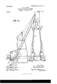
- Figure 1 is a view in section showing the ore-storage pile, the loading and unloading apparatus, and movable bins; and Fig. 2 is a similar view showing the bins and furnace and apparatus for conveying the ore, lime, and coke to the top of the furnace.
- 1 represents an ore-storage pile located between the tracks 2, on which the towers 3, carrying the overhead conveyor 4:, travel.
- This ore is deposited on the pile from transfer-cars 5, which run on the trestle 6, and the ore dis- .charged at the side of the trestle 6 is taken up and distributed over the pile by the excavating-bucket 7 which latter is carried by ropes or chains depending from the trolley 4, which moves on the overheadconveyer or crane 9.
- the ore not needed for immediate use is deposited on this storage pile.
- movable bins some of which are used forcoke and limestone and others for ore. These bins are mounted on wheeltrucks which move on trackways 12 and 13, and as the bins are movable it will be seen that the number necessary to keep a furnace properly supplied will be greatly less than the number of stationary bins necessary for a furnace of the same capacity. There are variousgrades of ore, and if a furnace is working one particular grade all bins filled with other grades are necessarily idle. 'With my system of movable bins the latter may befilled with the particular grade of ore being used, and thus do away entirely with the necessity for any more bins than are actually necessary to keep the furnace supplied with the ore, coke, and limestone.
- the bins 10 are each provided with an inclined bottom and a side gate through which the material is discharged, and the one or more bins for supplying the furnace with ore are preferably located on one track 12, while those for supplying the coke and limestone are located on a parallel track 13, the discharge-gates of the two bins opening toward each other, so as to discharge their contents into the scale-lorry 15, which is located and runs on a track 14, located slightly below the grade, as shown in Fig. 2.
- This scale-lorry travels to a point adjacent to the furnace or furnaces, and if supplying more than one furnace to a point adjacent each, while the bins 10 are designed to travel from a point adjacent to the storage-pile to a point that can be reached by the lorry 15.
- the track 12, carrying the ore-bins preferably passes through a house 17 or other structure, where the ore can be stored to prevent freezing or the frozen or wet ore can be thawed or dried out, and the depressed track 14 for the lorry 15 is located betweentracks 12 and 13.
- the material in the bins is discharged directly into the scale-lorry and conveyed in the latter to a point over the skip-car 17, into which it is dumped.
- This car 1'7 travels on the skip-hoist track 16 and discharges the ore, coke, and limestone into the top of-furnace 18, as shown in Fig. 2.
- any ore intended for direct consumption instead of being discharged onto the ore pile can be loaded from the car or vessel directly into the bin.
- the trolley carrying the excavatingbucket 7 travels back and forth on the bridge or overhead conveyer ,and as the latter overhangs the tracks 12 and 13 the ore is discharged directly from the excavating-bucket 7 into the bins, and the latter are then moved to a point for discharging into the lorry, unless it is first necessary to dry or thaw out the ore, in which event the bin should run into the house 17. If the ore is not intended for immediate use, it can be runinto the house to prevent its freezing.
- Another advantage of my improved plant over those in use is that as the ore is handled directly into movable bins from the car or stock pile the expense of a bin-filling car on top of the trestle, which is necerneywith stationary bins, is avoided. This bin-filling car has been considered indispensable for the reason that it frequently happens that the.
- bins themselves can be moved to points directly under the overhead conveyer or bridge, and thus save not only the expense of the bin-filling cars, but also the time and labor necessary to manipulate them.
- the herein-described ore-handlingplant comprising a loading device, two sets of traveling bins to be moved adjacent to said loading device for the ore, and coke and limestone, a scale-lorry disposed between said sets of traveling bins and into which the bins discharge, and a skip arranged to receive material from the scale-lorry and carry it to the top of the furnace.
- the herein-described ore-handling plant comprising a loading device, traveling orebins to be moved adjacent to said loading device, an inclosure for a part of the track on which the ore-bins travel, a scale-lorry into which the contents of the bins are discharged, and a ship for carrying the ore to the top of the furnace.
- the herein-described ore-handling plant consisting of a loading device, a trackway adjacent to said loading device, a movable bin on said trackway, a depressedtrack adjacent to the track on which the bin travels, a scalelorry on said depressed track and adapted to receive the contents of the movable bin, and a skip into which the lorry discharges its contents.
- the herein-described ore-handling plant consisting of two trackways, movable bins thereon, means for filling said bins, a scalelorry mounted to travel between said trackways and into which the contents of the bins is discharged and a skip into which the lorry scale-lorry arranged to travel between said two series of traveling bins and to receive the material from both and conveying means arranged to receive the material from the scalelorry and discharge it into a furnace.
- the herein-described plant comprising a furnace, two traveling bins, a scale-lorry to be disposed between said bins and receive material therefrom, and a conveyor arranged to
Description
PATENTED MAR. 10, 1903.
G. H. HU'LETT.
PLANT FOR HANDLING ORES.
APPLICATION FILED MAY 3, 1902.
2 SHEETS-SHEET 1.
No MODEL.
W/TA/[SSES PATENTED MAIL-10,1903.
- G. H. HULETT.
PLANT FOR HANDLING 025s.
APPLICATION FILED MAY 3, 1902.
No MODEL.
2 SHEETS-SHEET 2.
I -x Z22 ArroR/mx UNITED STATES ATENT OFFICE.
GEORGE H. HULETT, OF CLEVELAND, OHIO.
PLANT FOR HANDLING ORES.
SPECIFICATION forming part of Letters Patent No. 722,425, dated March 10, 1903. Application filed May 3, 1902. Serial No. 105,797. (No model,)
T0 at whom it may concern:
Be it known that I, GEORGE H. HULETT, a resident of Cleveland, in the county of Guyahoga and State of Ohio, have invented certain new and useful Improvements inPlants for Handling Ores; and'I do hereby declare the following to be a full, clear, and exact description of the invention, such as will enable others skilled in the art to which it appertains to make and use the same.
My invention relates to an improved plant for handling ores.
In some of the plants or systems now in use the ore is received at the furnaces in railroadcars and discharged from the cars by suitable apparatus onto the stock or storage pile. The ore is then loaded from this storage pile into suitable wheelbarrows or wheeled carts and pushed by hand onto a scale, where it is weighed, and from thence to an elevator which carries it to the top of the furnacestack into which the ore is dumped. In more recent practice skips have been provided for taking the ore, coke, and lime to the top of the furnace, and when used the material is dumped from the barrow or cart into the skip, and in some other plants the ore is loaded into bin-filling cars which travel on a trestle above stationary elevated bins and discharge their contents through hopper-bottoms into the bins. The stationary bins are located in series under the trestle and are each provided with a discharge-outlet for discharging its contents into a scale car or lorry, which carries the ore, coke, or lime to the skip-car.
In all cases wherein bins have been used they have been located in elevated positions under trestles-and are necessarily made of sufficient strength to carry not only the large bodies of' objections other than that of the inital cost,
First, it is Well known that wet ore in the bins freezes in cold weather, thus rendering it exceedingly difficult to get the ore from the bins into the scale or lorry car and in some cases impossible without first building a fire under the bins to thaw them out. Again, large masses of soft wet ore become so packed in the bins that it will not gravitate through the doors of the bins, but must be worked out with bars. The object, therefore, of the present invention is to provide a plant or system of handling ores whereby the ores are discharged directly into a movable bin and conveyed in the bin to the scale-lorry, combined with suitable loading means for the bins and housing, into which the bins may be run when it becomes necessary to prevent wet ore from freezing or to thaw out frozen ore or dry up wet ore.
In the accompanying drawings, Figure 1 is a view in section showing the ore-storage pile, the loading and unloading apparatus, and movable bins; and Fig. 2 is a similar view showing the bins and furnace and apparatus for conveying the ore, lime, and coke to the top of the furnace.
1 represents an ore-storage pile located between the tracks 2, on which the towers 3, carrying the overhead conveyor 4:, travel. This ore is deposited on the pile from transfer-cars 5, which run on the trestle 6, and the ore dis- .charged at the side of the trestle 6 is taken up and distributed over the pile by the excavating-bucket 7 which latter is carried by ropes or chains depending from the trolley 4, which moves on the overheadconveyer or crane 9. The ore not needed for immediate use is deposited on this storage pile.
10 represents movable bins, some of which are used forcoke and limestone and others for ore. These bins are mounted on wheeltrucks which move on trackways 12 and 13, and as the bins are movable it will be seen that the number necessary to keep a furnace properly supplied will be greatly less than the number of stationary bins necessary for a furnace of the same capacity. There are variousgrades of ore, and if a furnace is working one particular grade all bins filled with other grades are necessarily idle. 'With my system of movable bins the latter may befilled with the particular grade of ore being used, and thus do away entirely with the necessity for any more bins than are actually necessary to keep the furnace supplied with the ore, coke, and limestone.
The bins 10, the construction of which forms the subject-matter of a separate application, are each provided with an inclined bottom and a side gate through which the material is discharged, and the one or more bins for supplying the furnace with ore are preferably located on one track 12, while those for supplying the coke and limestone are located on a parallel track 13, the discharge-gates of the two bins opening toward each other, so as to discharge their contents into the scale-lorry 15, which is located and runs on a track 14, located slightly below the grade, as shown in Fig. 2. This scale-lorry travels to a point adjacent to the furnace or furnaces, and if supplying more than one furnace to a point adjacent each, while the bins 10 are designed to travel from a point adjacent to the storage-pile to a point that can be reached by the lorry 15. The track 12, carrying the ore-bins, preferably passes through a house 17 or other structure, where the ore can be stored to prevent freezing or the frozen or wet ore can be thawed or dried out, and the depressed track 14 for the lorry 15 is located betweentracks 12 and 13. The material in the bins is discharged directly into the scale-lorry and conveyed in the latter to a point over the skip-car 17, into which it is dumped. This car 1'7 travels on the skip-hoist track 16 and discharges the ore, coke, and limestone into the top of-furnace 18, as shown in Fig. 2.
Any ore intended for direct consumption instead of being discharged onto the ore pile can be loaded from the car or vessel directly into the bin. When loadingjhe bins from the pile, the trolley carrying the excavatingbucket 7 travels back and forth on the bridge or overhead conveyer ,and as the latter overhangs the tracks 12 and 13 the ore is discharged directly from the excavating-bucket 7 into the bins, and the latter are then moved to a point for discharging into the lorry, unless it is first necessary to dry or thaw out the ore, in which event the bin should run into the house 17. If the ore is not intended for immediate use, it can be runinto the house to prevent its freezing.
By handling the ore direct from the cars or stock pile and having only a days supply in the bins the difficulties encountered with frozen or wet ores are entirely removed.
Another advantage of my improved plant over those in use is that as the ore is handled directly into movable bins from the car or stock pile the expense of a bin-filling car on top of the trestle, which is necessaiywith stationary bins, is avoided. This bin-filling car has been considered indispensable for the reason that it frequently happens that the.
particular ore required for a particular bin is liable to be so far removed from the bin that it could not be handled by the overhead conveyer, hence must be first loaded into the binfilling car and discharged from the latter into the bin. With my plant the bins themselves can be moved to points directly under the overhead conveyer or bridge, and thus save not only the expense of the bin-filling cars, but also the time and labor necessary to manipulate them.
In my plant no elevated tracks or bins are required, and by the use of movable bins the number of bins required will be very much less than is possible where they are sta-' tionary.
It is evident that changes in the construction and relative arrangement of the several parts might be made without avoiding my invention, and hence I would have it understood that I do not restrict myself to the particular construction and arrangement of parts shown and described; but,
Having fully described my invention, what I claim as new, and desire to secure by Letters Patent, is
1. The herein-described ore-handlingplant, comprising a loading device, two sets of traveling bins to be moved adjacent to said loading device for the ore, and coke and limestone, a scale-lorry disposed between said sets of traveling bins and into which the bins discharge, and a skip arranged to receive material from the scale-lorry and carry it to the top of the furnace.
2. The herein-described ore-handling plant, comprising a loading device, traveling orebins to be moved adjacent to said loading device, an inclosure for a part of the track on which the ore-bins travel, a scale-lorry into which the contents of the bins are discharged, and a ship for carrying the ore to the top of the furnace.
3. The herein-described ore-handling plant consisting of a loading device, a trackway adjacent to said loading device, a movable bin on said trackway, a depressedtrack adjacent to the track on which the bin travels, a scalelorry on said depressed track and adapted to receive the contents of the movable bin, and a skip into which the lorry discharges its contents.
4. The herein-described ore-handlin g plant, consisting of parallel tracks, movable bins thereon, a depressed track intermediate the parallel tracks,a scale-lorry on said depressed track and adapted to receive the contents of the bins on bothsides of same, and a skip into which the lorry discharges its contents.
5. The herein-described ore-handling plant consisting of two trackways, movable bins thereon, means for filling said bins, a scalelorry mounted to travel between said trackways and into which the contents of the bins is discharged and a skip into which the lorry scale-lorry arranged to travel between said two series of traveling bins and to receive the material from both and conveying means arranged to receive the material from the scalelorry and discharge it into a furnace.
7. The herein-described plant, comprising a furnace, two traveling bins, a scale-lorry to be disposed between said bins and receive material therefrom, and a conveyor arranged to
Priority Applications (1)
| Application Number | Priority Date | Filing Date | Title |
|---|---|---|---|
| US10579702A US722425A (en) | 1902-05-03 | 1902-05-03 | Plant for handling ores. |
Applications Claiming Priority (1)
| Application Number | Priority Date | Filing Date | Title |
|---|---|---|---|
| US10579702A US722425A (en) | 1902-05-03 | 1902-05-03 | Plant for handling ores. |
Publications (1)
| Publication Number | Publication Date |
|---|---|
| US722425A true US722425A (en) | 1903-03-10 |
Family
ID=2790940
Family Applications (1)
| Application Number | Title | Priority Date | Filing Date |
|---|---|---|---|
| US10579702A Expired - Lifetime US722425A (en) | 1902-05-03 | 1902-05-03 | Plant for handling ores. |
Country Status (1)
| Country | Link |
|---|---|
| US (1) | US722425A (en) |
Cited By (1)
| Publication number | Priority date | Publication date | Assignee | Title |
|---|---|---|---|---|
| US6555049B1 (en) * | 2000-02-01 | 2003-04-29 | Kress Corporation | Steel manufacturing facility and method |
-
1902
- 1902-05-03 US US10579702A patent/US722425A/en not_active Expired - Lifetime
Cited By (1)
| Publication number | Priority date | Publication date | Assignee | Title |
|---|---|---|---|---|
| US6555049B1 (en) * | 2000-02-01 | 2003-04-29 | Kress Corporation | Steel manufacturing facility and method |
Similar Documents
| Publication | Publication Date | Title |
|---|---|---|
| US722425A (en) | Plant for handling ores. | |
| US6676357B2 (en) | Arcuate bulk storage facility | |
| WO2000046131A1 (en) | A storage facility for various bulk materials | |
| WO2022166261A1 (en) | M-shaped closed stockyard | |
| US1942839A (en) | Self-unloading boat | |
| US1222219A (en) | Apparatus for unloading and distributing materials. | |
| CN207090268U (en) | A kind of universal top direct dismounting type horizontal warehouse of road and rail | |
| US20030041771A1 (en) | Angled cargo discharge gate | |
| WO2012049633A1 (en) | Bulk material loading arrangement | |
| SK280375B6 (en) | Set for catching and transportation of ballast, waste or another loose material | |
| CN107380881A (en) | A kind of universal top direct dismounting type horizontal warehouse of road and rail | |
| Efremenkov | Specifics of Technology for Unloading and Storing Unconditioned Quartz Sand in Batch Houses | |
| US792735A (en) | Furnace-filling apparatus. | |
| WO1992005997A1 (en) | Unloading means for bulk material | |
| US782694A (en) | Storage apparatus. | |
| US3471041A (en) | Apparatus for depositing material in and removing it from elongated processing zones | |
| US1496196A (en) | Method of and apparatus for transporting materials | |
| AU779773B2 (en) | A storage facility for various bulk materials | |
| JPS624695A (en) | Hold structure of bulk cargo ship | |
| US812084A (en) | Coal-handling plant. | |
| RU68445U1 (en) | DEVICE FOR OVERLOADING BULK MATERIAL FROM RAILWAY CARS | |
| US591696A (en) | rothenbach | |
| US1324184A (en) | Francis lee stuart | |
| US800231A (en) | Unloading, storing, and reclaiming apparatus. | |
| US1320377A (en) | Process of unloading grain cars |