US720464A - Device for washing and drying films. - Google Patents
Device for washing and drying films. Download PDFInfo
- Publication number
- US720464A US720464A US11796902A US1902117969A US720464A US 720464 A US720464 A US 720464A US 11796902 A US11796902 A US 11796902A US 1902117969 A US1902117969 A US 1902117969A US 720464 A US720464 A US 720464A
- Authority
- US
- United States
- Prior art keywords
- base
- sections
- posts
- washing
- film
- Prior art date
- Legal status (The legal status is an assumption and is not a legal conclusion. Google has not performed a legal analysis and makes no representation as to the accuracy of the status listed.)
- Expired - Lifetime
Links
Images

Classifications
-
- G—PHYSICS
- G03—PHOTOGRAPHY; CINEMATOGRAPHY; ANALOGOUS TECHNIQUES USING WAVES OTHER THAN OPTICAL WAVES; ELECTROGRAPHY; HOLOGRAPHY
- G03D—APPARATUS FOR PROCESSING EXPOSED PHOTOGRAPHIC MATERIALS; ACCESSORIES THEREFOR
- G03D13/00—Processing apparatus or accessories therefor, not covered by groups G11B3/00 - G11B11/00
- G03D13/02—Containers; Holding-devices
- G03D13/08—Devices for holding exposed material; Devices for supporting exposed material
- G03D13/12—Frames
Definitions
- n4 ucnms PEYERS cu, PMOTO-LITHQ. wumnm'ou, a. c.
- Myinvention relates to a device especially designed for washing and drying photographic films; and the purpose of the invention is to provide a simple, light, durable, and economic device adapted to accommodate any desired length of films and films of any marketable width, whereby to conveniently operate a film in a body of water for the purpose of washing the same and to speedily dry the films after washing, both of which operations can be expeditiously performed without danger of marring the films.
- Another purpose of the invention is to so construct the device that two or more adjustable uprights or posts may be employed as guides for the films and whereby the supports for the uprights or posts may be adjusted in many ways relative to each other, so that the film in band form can be held in the most convenient manner for the operation at hand.
- Another purpose of the invention is to provide a means whereby the device may be secured to any convenient support-an edge of a table or bench, for exampleand be more or less rapidly rotated.
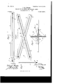
- Figure 1 is a perspective view of the device, showing one position in which the film may be held.
- Fig. 2 is a transverse section on the line 2 2 of Fig. 1.
- Fig. 3 is a plan view of the device, showing another adjustment thereof.
- Fig. 4 is a plan view of the device adjusted as shown in Fig. 1 and illustrating the adaptation of three guides for the film.
- FIG. 5 a front elevation of the device, drawn on a smaller scale, in which the device is shown Fig. 5 is.
- Fig. 6 is a section taken practically on the line 6 6 of Fig. 5; and Fig. 7 is a side elevation of a guide-post, showing a longitudinal slot therein.
- the device consists of two base-sections A and B, adjustable guide-posts 0, carried by the base-sections, and a locking mechanism D.
- the base-sections are preferably in the form of bars or strips of any desired length and width and are made of any suitable strong yet light material.
- Each base-section A and B is provided with a longitudinal slot 10, extending nearly the length of the section, and preferably one base-section at one end is provided with an aperture 11, enabling the device to be hung ,up for drying purposes when desired.
- the guide-posts C have their lower ends 12 threaded, and at the upper ends of the threads collars 13 are attached or are integrally formed upon the guide-posts.
- the threaded ends of the posts are loosely passed through the slots 10 in the base-sectionsA and B, so that they may be carried to any point in the length of the slots, and the posts are secured in their adjusted position by winged nuts 14 or their equivalents at the threaded portions of the guide-posts, the nuts bearing against the back face of the base-sections and the collars having bearing against the front faces of said base-sections as is shown in Fig. 2.
- the guide-posts are provided with longitudinal slots, as is shown in Fig. 7, in which the ends of the film may be inserted and secured by rotating the post previously loosened at its base, which rotation locks the film to the post by rolling it up upon itself.
- the two base-sections A and B are adjustably connected by means of the aforesaid locking mechanism D.
- This locking mechanism consists, primarily, of a suitably-headed bolt 15 and lock-nut 16, the bolt being passed through the slot 10 of each base-section, and the locknut is at the rear end of the bolt. It is often desirable to attach the device to a support and to impart rotary motion to the device while thus connected or while held in the hand. To that end a drum 17 is apertured to loosely slide over the threaded portion of the bolt 15, as is best shown in Fig. 6, being held securely against the base-sections when the latter are adjusted by the look 16, which engages with the drum.
- a nut 23 is screwed upon the bolt, as is likewise shown in Fig. 6, whereby the device, with the bolt as a pivot, may freely turn upon the clamp.
- the necessary rotary motion is imparted to the device preferably by means of a cord attached at one end to the drum 17 and wound thereon, so that by pulling upon the cord and then releasing it to slacken the cord for rewinding the device may be revolved at any desired speed.
- the film is more rapidly dried by whirling the device quickly, which causes the moisture in the film to be thrown off by centrifugal force.
- the film E before being placed upon the device has its ends attached together in any approved manner, so as to form an endless belt or band, and the guide-posts C are passed between the stretches or inner surfaces of the band-film, as is shown in Figs. 1, 4, and 5.
- Fig. l I have illustrated the base-sections A and B as crossed one upon the other in substantially the form of an X and as provided with two guide-posts at one end, one at the corresponding extremity of each base-section, so that the film in this instance is held transversely of the device at one of its ends.
- Fig. 4 I have illustrated the base-sections in substantially the same position as is shown in Fig. 1; but three guide-posts C are employed-two at one end of the device and one at the otherend-whereby when the film is carried around these posts it has substantially a triangular form in plan View.
- Fig. 5 I have illustrated the base-sections A and B as placed at rightangles to each other, crossing one another at their centers, and in this arrangement of the base-sections four guide-posts C are preferably employed, one being located at each end of each base-section A and B, so that when the film is held in position by the four guide-posts the film will have a rectangular contour in plan.
- Fig. 3 I have illustrated the two basesections as placed one over the other in parallelism and two guide-posts located at opposite sides of the sections. Under this ar rangement of the device when the film is placed in position thereon it will extend longitudinally of the device.
- the device is susceptible of modifications without material departure from the principles and spirit of the invention, and for this reason I do not Wish to be understood as limiting myself to the precise form of the parts herein set forth. It is also obvious that the device can be conveniently employed in the development and washing of films by the suspension underneath the device from the edge of a table of a suitable vessel containing a developer or water and rotating the lower part of the device through it.
- base'sections adjustable one upon the other, longitudinally, transversely and diagonally, a locking mechanism for the base-sections, and removable longitudinally-slotted guideposts adjustable longitudinally of the base sections, as described.
- base sections adjustable relative to each other, a locking mechanism for the base-sections, guide-posts adjustably carried by the base-sections, and means constituting a portion of the locking mechanism for imparting rotary movement to the base-sections, as set forth.
- a device for washing and drying films the combination with base-sections consisting of strips or bars having longitudinal slots therein, of a locking-bolt passed through the slots in the base-sections, and guide-posts fitted to slide in the slots of the said base-sections, which guide-posts are provided with collars having bearing upon one face of the base-sections and with locking-nuts having bearing against the opposing faces of the base-sections, as and for the purpose set forth.
- a device for washing and drying films the combination with two base-bars having longitudinal slots therein lying one upon the other, of a locking-bolt passed through the slots of the said base-bars, a clamp in which one end of a locking-bolt is mounted to turn, a lock-nut for the locking-bolt, a drum held on the locking-bolt between the lock-nut and the base-bars, a cord attached to and wound upon the said drum, posts mounted to slide in the slots of the base-bars, and locking devices for the posts, as and for the purpose described.
Description
No. 720,464. PATBNTED FEB. 10, 1903. E. W. NEWGOMB. DEVICE FOR WASHING AND DRYING FILMS.
APPLICATION FILED AUG. 1, 1902.
H0 MODEL. I
2 SHEETS-SHEET 1.
2 //v VENTOFI Edward Muzz /1M m: yonms PETERS co. Pnm'ou'ma. WAWINOTON.-D: c.
No. 720,464. Q PATENTED FEB. 10, 1903. E. W. NEWOOMB. DEVICE FOR WASHING AND DRYING FILMS.
APPLICATION FILED AUG. 11 1902.
N0 MgDEL. 2 SHEETS-SHEET 2.
A T TOR/V E YS.
n4: ucnms PEYERS cu, PMOTO-LITHQ. wumnm'ou, a. c.
UNITED STATES PATENT OEEICE.
EDTVARD WVEBBER NEWCOMB, OF NEW YORK, N. Y.
DEVICE FOR WASHING AND DRYING FILMS.
z-PECIFICATION forming part of Letters Patent N 0. 720,464, dated February 10, 1903.
Application filed August 1, 1902. Serial No. 117,969. (No model.)
To aZZ whom it rncty concern:
Beit known that I, EDWARD WEBBER NEW- COHB, a citizen of the United States, and a resident of the city of New York, borough of Manhattan, in the county and State of New York, have invented a new and Improved De vice for Washing and Drying Films, of which the following is a full, clear, and exact description.
Myinvention relates to a device especially designed for washing and drying photographic films; and the purpose of the invention is to provide a simple, light, durable, and economic device adapted to accommodate any desired length of films and films of any marketable width, whereby to conveniently operate a film in a body of water for the purpose of washing the same and to speedily dry the films after washing, both of which operations can be expeditiously performed without danger of marring the films.
Another purpose of the invention is to so construct the device that two or more adjustable uprights or posts may be employed as guides for the films and whereby the supports for the uprights or posts may be adjusted in many ways relative to each other, so that the film in band form can be held in the most convenient manner for the operation at hand.
Another purpose of the invention is to provide a means whereby the device may be secured to any convenient support-an edge of a table or bench, for exampleand be more or less rapidly rotated.
The invention consists in the novel construction and combination of the several parts, as will be hereinafter fully set forth, and pointed out in the claims.
Reference is to be had to the accompanying drawings, forming a part of this specification, in which similar characters of reference indicate corresponding parts in all the figures.
Figure 1 is a perspective view of the device, showing one position in which the film may be held. Fig. 2 is a transverse section on the line 2 2 of Fig. 1. Fig. 3 is a plan view of the device, showing another adjustment thereof. Fig. 4 is a plan view of the device adjusted as shown in Fig. 1 and illustrating the adaptation of three guides for the film.
a front elevation of the device, drawn on a smaller scale, in which the device is shown Fig. 5 is.
attached to the edge of a table and four guides employed for the film. Fig. 6 is a section taken practically on the line 6 6 of Fig. 5; and Fig. 7 is a side elevation of a guide-post, showing a longitudinal slot therein.
The device consists of two base-sections A and B, adjustable guide-posts 0, carried by the base-sections, and a locking mechanism D. The base-sections are preferably in the form of bars or strips of any desired length and width and are made of any suitable strong yet light material. Each base-section A and B is provided with a longitudinal slot 10, extending nearly the length of the section, and preferably one base-section at one end is provided with an aperture 11, enabling the device to be hung ,up for drying purposes when desired. The guide-posts C have their lower ends 12 threaded, and at the upper ends of the threads collars 13 are attached or are integrally formed upon the guide-posts. The threaded ends of the posts are loosely passed through the slots 10 in the base-sectionsA and B, so that they may be carried to any point in the length of the slots, and the posts are secured in their adjusted position by winged nuts 14 or their equivalents at the threaded portions of the guide-posts, the nuts bearing against the back face of the base-sections and the collars having bearing against the front faces of said base-sections as is shown in Fig. 2. The guide-posts are provided with longitudinal slots, as is shown in Fig. 7, in which the ends of the film may be inserted and secured by rotating the post previously loosened at its base, which rotation locks the film to the post by rolling it up upon itself. The two base-sections A and B are adjustably connected by means of the aforesaid locking mechanism D. This locking mechanism consists, primarily, of a suitably-headed bolt 15 and lock-nut 16, the bolt being passed through the slot 10 of each base-section, and the locknut is at the rear end of the bolt. It is often desirable to attach the device to a support and to impart rotary motion to the device while thus connected or while held in the hand. To that end a drum 17 is apertured to loosely slide over the threaded portion of the bolt 15, as is best shown in Fig. 6, being held securely against the base-sections when the latter are adjusted by the look 16, which engages with the drum. The rear end 18 of the bolt is smooth and is loosely passed through an aperture 19 in aclamp 20, having suitably-applied set-screws 21 to secure the clamp to a table or bench 22 or a like support= Within the clamp a nut 23 is screwed upon the bolt, as is likewise shown in Fig. 6, whereby the device, with the bolt as a pivot, may freely turn upon the clamp. The necessary rotary motion is imparted to the device preferably by means of a cord attached at one end to the drum 17 and wound thereon, so that by pulling upon the cord and then releasing it to slacken the cord for rewinding the device may be revolved at any desired speed. The film is more rapidly dried by whirling the device quickly, which causes the moisture in the film to be thrown off by centrifugal force. The film E before being placed upon the device has its ends attached together in any approved manner, so as to form an endless belt or band, and the guide-posts C are passed between the stretches or inner surfaces of the band-film, as is shown in Figs. 1, 4, and 5.
In Fig. l I have illustrated the base-sections A and B as crossed one upon the other in substantially the form of an X and as provided with two guide-posts at one end, one at the corresponding extremity of each base-section, so that the film in this instance is held transversely of the device at one of its ends.
In Fig. 4 I have illustrated the base-sections in substantially the same position as is shown in Fig. 1; but three guide-posts C are employed-two at one end of the device and one at the otherend-whereby when the film is carried around these posts it has substantially a triangular form in plan View.
In Fig. 5 I have illustrated the base-sections A and B as placed at rightangles to each other, crossing one another at their centers, and in this arrangement of the base-sections four guide-posts C are preferably employed, one being located at each end of each base-section A and B, so that when the film is held in position by the four guide-posts the film will have a rectangular contour in plan.
In Fig. 3 I have illustrated the two basesections as placed one over the other in parallelism and two guide-posts located at opposite sides of the sections. Under this ar rangement of the device when the film is placed in position thereon it will extend longitudinally of the device.
It is obvious that many adjustments of the base-sections are obtainable and that any desired number of guide-posts for the film may be employed, the said guide-posts may be adjusted on the base-sections, and the base-sections may be adjusted relative to each other to accommodate any length of film, and that the film may be so placed on the device that it may be most conveniently dried or washed with the conveniences at hand.
It will be obvious from the above description of the invention that the device is susceptible of modifications without material departure from the principles and spirit of the invention, and for this reason I do not Wish to be understood as limiting myself to the precise form of the parts herein set forth. It is also obvious that the device can be conveniently employed in the development and washing of films by the suspension underneath the device from the edge of a table of a suitable vessel containing a developer or water and rotating the lower part of the device through it.
Having thus described my invention, I claim as new and desire to secure by Letters Patent 1. In a device for washing and drying films, base -sections adjustable relative to each other, a locking mechanism for the base-sections, and guide-posts adjustably carried by the base-sections, as described.
2. In a device for washing and drying films, base'sections adjustable one upon the other, longitudinally, transversely and diagonally, a locking mechanism for the base-sections, and removable longitudinally-slotted guideposts adjustable longitudinally of the base sections, as described.
3. In a device for washing and drying films, base sections adjustable relative to each other, a locking mechanism for the base-sections, guide-posts adjustably carried by the base-sections, and means constituting a portion of the locking mechanism for imparting rotary movement to the base-sections, as set forth.
4. In a device for washing and drying films, the combination with base-sections consisting of strips or bars having longitudinal slots therein, of a locking-bolt passed through the slots in the base-sections, and guide-posts fitted to slide in the slots of the said base-sections, which guide-posts are provided with collars having bearing upon one face of the base-sections and with locking-nuts having bearing against the opposing faces of the base-sections, as and for the purpose set forth.
5. In a device for washing and drying films, the combination with two base-bars having longitudinal slots therein lying one upon the other, of a locking-bolt passed through the slots of the said base-bars, a clamp in which one end of a locking-bolt is mounted to turn, a lock-nut for the locking-bolt, a drum held on the locking-bolt between the lock-nut and the base-bars, a cord attached to and wound upon the said drum, posts mounted to slide in the slots of the base-bars, and locking devices for the posts, as and for the purpose described.
In testimony whereof I have signed my name to this specification in the presence of two subscribing witnesses.
EDWARD WEBBER NEWGOlllB.
Witnesses:
THERESA PFEIFFER, MARION O. TOOLE.
ICC
Priority Applications (1)
| Application Number | Priority Date | Filing Date | Title |
|---|---|---|---|
| US11796902A US720464A (en) | 1902-08-01 | 1902-08-01 | Device for washing and drying films. |
Applications Claiming Priority (1)
| Application Number | Priority Date | Filing Date | Title |
|---|---|---|---|
| US11796902A US720464A (en) | 1902-08-01 | 1902-08-01 | Device for washing and drying films. |
Publications (1)
| Publication Number | Publication Date |
|---|---|
| US720464A true US720464A (en) | 1903-02-10 |
Family
ID=2788979
Family Applications (1)
| Application Number | Title | Priority Date | Filing Date |
|---|---|---|---|
| US11796902A Expired - Lifetime US720464A (en) | 1902-08-01 | 1902-08-01 | Device for washing and drying films. |
Country Status (1)
| Country | Link |
|---|---|
| US (1) | US720464A (en) |
-
1902
- 1902-08-01 US US11796902A patent/US720464A/en not_active Expired - Lifetime
Similar Documents
| Publication | Publication Date | Title |
|---|---|---|
| US3761085A (en) | Table tennis practice and game equipment | |
| US3226861A (en) | Stretching rack | |
| US720464A (en) | Device for washing and drying films. | |
| US904563A (en) | Machine for making wall-ties. | |
| US891228A (en) | Clothes-bar. | |
| US577472A (en) | white | |
| US2418581A (en) | Bean and pea pod splitter | |
| US3304850A (en) | Apparatus for processing photographic materials | |
| US967734A (en) | Fishing-line-drying reel. | |
| US392779A (en) | Henry g | |
| US1281318A (en) | Folding laundry-rack. | |
| US780826A (en) | Separator. | |
| US370409A (en) | Drawing-board | |
| US1587766A (en) | Spinning top | |
| US2915889A (en) | Rug cleaning device | |
| US898051A (en) | Apparatus for drying clothes. | |
| US1006381A (en) | Bath accessory. | |
| US3139190A (en) | Collapsible clothesline dryer | |
| US778872A (en) | Drawing-table. | |
| US648745A (en) | Drying and stretching frame. | |
| US461274A (en) | Device for supporting tobacco-laths | |
| US392259A (en) | Geoege e | |
| US1472591A (en) | Island | |
| US694500A (en) | Music-rack. | |
| US1345030A (en) | Fabric-frame |