US7192306B2 - High voltage connector - Google Patents
High voltage connector Download PDFInfo
- Publication number
- US7192306B2 US7192306B2 US11/175,615 US17561505A US7192306B2 US 7192306 B2 US7192306 B2 US 7192306B2 US 17561505 A US17561505 A US 17561505A US 7192306 B2 US7192306 B2 US 7192306B2
- Authority
- US
- United States
- Prior art keywords
- hollow body
- thread
- closed
- connector
- extending
- Prior art date
- Legal status (The legal status is an assumption and is not a legal conclusion. Google has not performed a legal analysis and makes no representation as to the accuracy of the status listed.)
- Expired - Fee Related
Links
Images


Classifications
-
- H—ELECTRICITY
- H01—ELECTRIC ELEMENTS
- H01R—ELECTRICALLY-CONDUCTIVE CONNECTIONS; STRUCTURAL ASSOCIATIONS OF A PLURALITY OF MUTUALLY-INSULATED ELECTRICAL CONNECTING ELEMENTS; COUPLING DEVICES; CURRENT COLLECTORS
- H01R13/00—Details of coupling devices of the kinds covered by groups H01R12/70 or H01R24/00 - H01R33/00
- H01R13/46—Bases; Cases
- H01R13/53—Bases or cases for heavy duty; Bases or cases for high voltage with means for preventing corona or arcing
Definitions
- the present invention relates to high voltage connectors used for connecting high voltage leads to equipment.
- Conventional connectors are made of a synthetic material and are available from companies such as Jettron Products, Inc. and Caton Connector Corp.
- Such conventional connectors or receptacles are generally, as shown in FIGS. 1 and 2 , attached to equipment by being embedded in a potting compound as shown in FIG. 1 , or mounted by a flange as shown in FIG. 2 .
- the main purpose of these connectors is to provide a stable connection which prevents arcing.
- a high voltage connector having a cylindrical hollow body with a first, closed end and a second, open end.
- a first external thread extends from the first end towards the second end along a portion of the length of the body.
- a second external thread extends from the second, open end toward the first end over a portion of the length of the hollow body.
- a metal element is mounted to the closed end of the hollow body so as to be concentric with the hollow body.
- the metal element has an eyelet that projects axially from the closed end.
- the metal element also has a pin that projects concentrically into the hollow body.
- the first thread and the second thread are different.
- the first thread can be coarser than the second thread, or vice versa.
- first thread and the second thread extend along the hollow body for substantially equal lengths.
- first thread can, as needed, extend over a greater or lesser length of the hollow body than the second thread.
- the first end of the hollow body has a different diameter than the second end of the hollow body.
- the first end of the hollow body has a larger diameter than the second end.
- the larger diameter extends for more than half the length of the hollow body.
- Still another object of the present invention is to provide an improved sleeve for mounting the connectors.
- Sleeves are known in the prior art which are substantially cylindrical in shape and have a smooth internal bore.
- the internal bore is provided with a thread that mates with the first external thread of the hollow body of the connector whereby the connector can be threaded into the sleeve.
- FIG. 1 shows a prior art connector
- FIG. 2 shows another type of prior art connector
- FIG. 3 is side view of a connector pursuant to the present invention.
- FIG. 4 is an end view of FIG. 3 ;
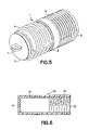
- FIG. 5 is a perspective view of the connector of FIG. 3 ;
- FIG. 6 is a cross-section through a sleeve of the present invention.
- the inventive high voltage connector as shown in FIG. 3 , has a cylindrical hollow body 1 with a first closed end 2 .
- a second end 3 is open.
- a first external thread 4 extends from the first end 2 toward the second end 3 over a portion of the length of the body 1 .
- a second external thread 5 extends from the second end 3 toward the first end 2 over a portion of the length of the hollow body 1 .
- FIG. 3 shows a central region 6 that has no threading.
- This unthreaded region can be of any desired length, depending upon the application in question. The same is true for the lengths of the first and second threads. The extent to which either of the threads extends over the length of the hollow body can be determined by those skilled in the art depending upon the specific application. The same holds true for the actual thread size.
- the closed end 2 is provided with a metal eyelet 7 and a pin 8 that extends coaxially in the interior of the hollow body 1 .
- the inventive connector of FIG. 3 provides that the first thread 4 allows the connector to be screwed into the component and then a potting compound 9 can additionally be added to encapsulate the first end of the connector, as shown in FIG. 1 . In this way, both a form locking and an adhesive connection are provided.
- FIG. 6 shows a cross-section through the inventive sleeve 10 .
- the sleeve is essentially a hollow cylindrical member having openings 11 , 12 at each end. The size of the openings 11 , 12 are determined by the specific application.
- the sleeve 10 also has a first unthreaded portion 13 and a threaded portion 14 .
- the threaded portion 14 is an internal thread that matches the external thread 4 on the first end 2 of the hollow body 1 .
- the diameters of the first and second portions 13 , 14 can be the same or different, depending upon the specific application.
- first threads 4 break up and add length to the path for potential arcs originating from the eyelet 7 .
- the partition region 6 provides a hard stop making it easier to mount the connector to a component.
Abstract
Description
Claims (8)
Priority Applications (1)
| Application Number | Priority Date | Filing Date | Title |
|---|---|---|---|
| US11/175,615 US7192306B2 (en) | 2005-07-06 | 2005-07-06 | High voltage connector |
Applications Claiming Priority (1)
| Application Number | Priority Date | Filing Date | Title |
|---|---|---|---|
| US11/175,615 US7192306B2 (en) | 2005-07-06 | 2005-07-06 | High voltage connector |
Publications (2)
| Publication Number | Publication Date |
|---|---|
| US20070010142A1 US20070010142A1 (en) | 2007-01-11 |
| US7192306B2 true US7192306B2 (en) | 2007-03-20 |
Family
ID=37618837
Family Applications (1)
| Application Number | Title | Priority Date | Filing Date |
|---|---|---|---|
| US11/175,615 Expired - Fee Related US7192306B2 (en) | 2005-07-06 | 2005-07-06 | High voltage connector |
Country Status (1)
| Country | Link |
|---|---|
| US (1) | US7192306B2 (en) |
Families Citing this family (1)
| Publication number | Priority date | Publication date | Assignee | Title |
|---|---|---|---|---|
| US8913611B2 (en) * | 2011-11-15 | 2014-12-16 | Nicira, Inc. | Connection identifier assignment and source network address translation |
Citations (3)
| Publication number | Priority date | Publication date | Assignee | Title |
|---|---|---|---|---|
| US2385191A (en) * | 1942-12-31 | 1945-09-18 | Gen Electric | Electrical connector |
| US2981920A (en) * | 1959-03-16 | 1961-04-25 | Kings Electronics Inc | Cable clamp |
| US3530423A (en) * | 1968-06-04 | 1970-09-22 | Continental Sensing Inc | Conductor assembly |
-
2005
- 2005-07-06 US US11/175,615 patent/US7192306B2/en not_active Expired - Fee Related
Patent Citations (3)
| Publication number | Priority date | Publication date | Assignee | Title |
|---|---|---|---|---|
| US2385191A (en) * | 1942-12-31 | 1945-09-18 | Gen Electric | Electrical connector |
| US2981920A (en) * | 1959-03-16 | 1961-04-25 | Kings Electronics Inc | Cable clamp |
| US3530423A (en) * | 1968-06-04 | 1970-09-22 | Continental Sensing Inc | Conductor assembly |
Also Published As
| Publication number | Publication date |
|---|---|
| US20070010142A1 (en) | 2007-01-11 |
Similar Documents
| Publication | Publication Date | Title |
|---|---|---|
| US10578141B1 (en) | Securing pin for securing structural members | |
| US7074081B2 (en) | Connector capable of firmly engaging an electric cord or an cable | |
| US6241553B1 (en) | Connector for electrical cords and cables | |
| US4447107A (en) | Collet for cable connector | |
| US5228875A (en) | Quick connect electrical connector | |
| CA2472991A1 (en) | Universal bus bar connector with multi-pitch threaded hole | |
| US20080236861A1 (en) | Kit or Set Comprising at Least Two Differently Dimensioned Types of Cable Glands | |
| WO2001079739A3 (en) | Screw on connector | |
| CA2226709A1 (en) | Anti-cross threading fastener | |
| EP2652840B1 (en) | Cable gland | |
| AU2014216049A1 (en) | Torque controlling break screw | |
| MX2008008903A (en) | Bushing well with improved coupling components. | |
| EP0935310B1 (en) | Contact element having a screw connection | |
| RU2008113197A (en) | INSERT FOR PLACEMENT IN THE ELEMENT FOR FIXING AND SECURING THE ELECTRICAL CONTACT OF THE CABLE CONNECTING TERMINAL | |
| CN107013550A (en) | Fastener assembly | |
| US6459233B1 (en) | Cable attachment assembly for battery of vehicle | |
| US7192306B2 (en) | High voltage connector | |
| US4782197A (en) | Electrical bushing having a replaceable stud | |
| US7931508B1 (en) | Multi-fit transformer stud mounting and methods of making the same | |
| US8430687B2 (en) | Method and apparatus for a snap retained push-on connector with port adapter | |
| US20070066116A1 (en) | Cable feed-through | |
| CA2511031A1 (en) | Transformer stud connector with improved conductivity using a special thread profile | |
| US7338312B2 (en) | Universal cable and work box connector | |
| EP1524732B1 (en) | Electrical connector | |
| DE4404543C2 (en) | Arrangement for automotive electrics for connecting a connecting cable to an electrical functional element |
Legal Events
| Date | Code | Title | Description |
|---|---|---|---|
| AS | Assignment |
Owner name: ULTRAVOLT, INC., NEW YORK Free format text: ASSIGNMENT OF ASSIGNORS INTEREST;ASSIGNORS:MORRISON, JAMES;MATCH, PETER;TANNER, JOHN D.;AND OTHERS;REEL/FRAME:016766/0083;SIGNING DATES FROM 20050602 TO 20050614 |
|
| AS | Assignment |
Owner name: ULTRA VOLT, INC., NEW JERSEY Free format text: ASSIGNMENT OF ASSIGNORS INTEREST;ASSIGNORS:MORRISON, JAMES;MATCH, PETER;TANNER, JOHN D.;AND OTHERS;REEL/FRAME:017549/0516 Effective date: 20050623 |
|
| AS | Assignment |
Owner name: PNC BANK, NATIONAL ASSOCIATION, PENNSYLVANIA Free format text: SECURITY AGREEMENT;ASSIGNOR:ULTRAVOLT, INC.;REEL/FRAME:020555/0281 Effective date: 20080208 |
|
| FPAY | Fee payment |
Year of fee payment: 4 |
|
| AS | Assignment |
Owner name: ULTRAVOLT, INC., NEW YORK Free format text: TERMINATION AND RELEASE OF IP SECURITY AGREEMENT;ASSIGNOR:PNC BANK, NATIONAL ASSOCIATION;REEL/FRAME:033523/0739 Effective date: 20140731 |
|
| REMI | Maintenance fee reminder mailed | ||
| LAPS | Lapse for failure to pay maintenance fees | ||
| STCH | Information on status: patent discontinuation |
Free format text: PATENT EXPIRED DUE TO NONPAYMENT OF MAINTENANCE FEES UNDER 37 CFR 1.362 |
|
| FP | Lapsed due to failure to pay maintenance fee |
Effective date: 20150320 |