US7170917B2 - Surface-emitting semiconductor laser - Google Patents

Surface-emitting semiconductor laser Download PDF

Info

Publication number
US7170917B2
US7170917B2 US10/468,183 US46818304A US7170917B2 US 7170917 B2 US7170917 B2 US 7170917B2 US 46818304 A US46818304 A US 46818304A US 7170917 B2 US7170917 B2 US 7170917B2
Authority
US
United States
Prior art keywords
layer
semiconductor laser
diffusion barrier
dielectric mirror
applying
Prior art date
Legal status (The legal status is an assumption and is not a legal conclusion. Google has not performed a legal analysis and makes no representation as to the accuracy of the status listed.)
Expired - Lifetime, expires
Application number
US10/468,183
Other versions
US20040179568A1 (en
Inventor
Markus-Christian Amann
Markus Ortsieffer
Current Assignee (The listed assignees may be inaccurate. Google has not performed a legal analysis and makes no representation or warranty as to the accuracy of the list.)
Vercilas GmbH
Vertilas GmbH
Original Assignee
Vercilas GmbH
Priority date (The priority date is an assumption and is not a legal conclusion. Google has not performed a legal analysis and makes no representation as to the accuracy of the date listed.)
Filing date
Publication date
Application filed by Vercilas GmbH filed Critical Vercilas GmbH
Assigned to VERTILAS GMBH reassignment VERTILAS GMBH ASSIGNMENT OF ASSIGNORS INTEREST (SEE DOCUMENT FOR DETAILS). Assignors: AMANN, MARKUS-CHRISTIAN, ORTSIEFFER, MARKUS
Publication of US20040179568A1 publication Critical patent/US20040179568A1/en
Application granted granted Critical
Publication of US7170917B2 publication Critical patent/US7170917B2/en
Adjusted expiration legal-status Critical
Assigned to SOUND POINT AGENCY LLC reassignment SOUND POINT AGENCY LLC SECURITY INTEREST Assignors: LUMILEDS HOLDING B.V., LUMILEDS LLC
Expired - Lifetime legal-status Critical Current

Links

Images

Classifications

    • HELECTRICITY
    • H01ELECTRIC ELEMENTS
    • H01SDEVICES USING THE PROCESS OF LIGHT AMPLIFICATION BY STIMULATED EMISSION OF RADIATION [LASER] TO AMPLIFY OR GENERATE LIGHT; DEVICES USING STIMULATED EMISSION OF ELECTROMAGNETIC RADIATION IN WAVE RANGES OTHER THAN OPTICAL
    • H01S5/00Semiconductor lasers
    • H01S5/10Construction or shape of the optical resonator, e.g. extended or external cavity, coupled cavities, bent-guide, varying width, thickness or composition of the active region
    • H01S5/18Surface-emitting [SE] lasers, e.g. having both horizontal and vertical cavities
    • H01S5/183Surface-emitting [SE] lasers, e.g. having both horizontal and vertical cavities having only vertical cavities, e.g. vertical cavity surface-emitting lasers [VCSEL]
    • H01S5/18361Structure of the reflectors, e.g. hybrid mirrors
    • H01S5/18369Structure of the reflectors, e.g. hybrid mirrors based on dielectric materials
    • HELECTRICITY
    • H01ELECTRIC ELEMENTS
    • H01SDEVICES USING THE PROCESS OF LIGHT AMPLIFICATION BY STIMULATED EMISSION OF RADIATION [LASER] TO AMPLIFY OR GENERATE LIGHT; DEVICES USING STIMULATED EMISSION OF ELECTROMAGNETIC RADIATION IN WAVE RANGES OTHER THAN OPTICAL
    • H01S5/00Semiconductor lasers
    • H01S5/04Processes or apparatus for excitation, e.g. pumping, e.g. by electron beams
    • H01S5/042Electrical excitation ; Circuits therefor
    • H01S5/0425Electrodes, e.g. characterised by the structure
    • H01S5/04252Electrodes, e.g. characterised by the structure characterised by the material
    • HELECTRICITY
    • H01ELECTRIC ELEMENTS
    • H01SDEVICES USING THE PROCESS OF LIGHT AMPLIFICATION BY STIMULATED EMISSION OF RADIATION [LASER] TO AMPLIFY OR GENERATE LIGHT; DEVICES USING STIMULATED EMISSION OF ELECTROMAGNETIC RADIATION IN WAVE RANGES OTHER THAN OPTICAL
    • H01S5/00Semiconductor lasers
    • H01S5/02Structural details or components not essential to laser action
    • H01S5/0206Substrates, e.g. growth, shape, material, removal or bonding
    • H01S5/0217Removal of the substrate
    • HELECTRICITY
    • H01ELECTRIC ELEMENTS
    • H01SDEVICES USING THE PROCESS OF LIGHT AMPLIFICATION BY STIMULATED EMISSION OF RADIATION [LASER] TO AMPLIFY OR GENERATE LIGHT; DEVICES USING STIMULATED EMISSION OF ELECTROMAGNETIC RADIATION IN WAVE RANGES OTHER THAN OPTICAL
    • H01S5/00Semiconductor lasers
    • H01S5/02Structural details or components not essential to laser action
    • H01S5/024Arrangements for thermal management
    • H01S5/02476Heat spreaders, i.e. improving heat flow between laser chip and heat dissipating elements
    • HELECTRICITY
    • H01ELECTRIC ELEMENTS
    • H01SDEVICES USING THE PROCESS OF LIGHT AMPLIFICATION BY STIMULATED EMISSION OF RADIATION [LASER] TO AMPLIFY OR GENERATE LIGHT; DEVICES USING STIMULATED EMISSION OF ELECTROMAGNETIC RADIATION IN WAVE RANGES OTHER THAN OPTICAL
    • H01S5/00Semiconductor lasers
    • H01S5/04Processes or apparatus for excitation, e.g. pumping, e.g. by electron beams
    • H01S5/042Electrical excitation ; Circuits therefor
    • H01S5/0421Electrical excitation ; Circuits therefor characterised by the semiconducting contacting layers
    • HELECTRICITY
    • H01ELECTRIC ELEMENTS
    • H01SDEVICES USING THE PROCESS OF LIGHT AMPLIFICATION BY STIMULATED EMISSION OF RADIATION [LASER] TO AMPLIFY OR GENERATE LIGHT; DEVICES USING STIMULATED EMISSION OF ELECTROMAGNETIC RADIATION IN WAVE RANGES OTHER THAN OPTICAL
    • H01S5/00Semiconductor lasers
    • H01S5/04Processes or apparatus for excitation, e.g. pumping, e.g. by electron beams
    • H01S5/042Electrical excitation ; Circuits therefor
    • H01S5/0425Electrodes, e.g. characterised by the structure
    • H01S5/04252Electrodes, e.g. characterised by the structure characterised by the material
    • H01S5/04253Electrodes, e.g. characterised by the structure characterised by the material having specific optical properties, e.g. transparent electrodes
    • HELECTRICITY
    • H01ELECTRIC ELEMENTS
    • H01SDEVICES USING THE PROCESS OF LIGHT AMPLIFICATION BY STIMULATED EMISSION OF RADIATION [LASER] TO AMPLIFY OR GENERATE LIGHT; DEVICES USING STIMULATED EMISSION OF ELECTROMAGNETIC RADIATION IN WAVE RANGES OTHER THAN OPTICAL
    • H01S5/00Semiconductor lasers
    • H01S5/10Construction or shape of the optical resonator, e.g. extended or external cavity, coupled cavities, bent-guide, varying width, thickness or composition of the active region
    • H01S5/18Surface-emitting [SE] lasers, e.g. having both horizontal and vertical cavities
    • H01S5/183Surface-emitting [SE] lasers, e.g. having both horizontal and vertical cavities having only vertical cavities, e.g. vertical cavity surface-emitting lasers [VCSEL]
    • H01S5/18308Surface-emitting [SE] lasers, e.g. having both horizontal and vertical cavities having only vertical cavities, e.g. vertical cavity surface-emitting lasers [VCSEL] having a special structure for lateral current or light confinement
    • HELECTRICITY
    • H01ELECTRIC ELEMENTS
    • H01SDEVICES USING THE PROCESS OF LIGHT AMPLIFICATION BY STIMULATED EMISSION OF RADIATION [LASER] TO AMPLIFY OR GENERATE LIGHT; DEVICES USING STIMULATED EMISSION OF ELECTROMAGNETIC RADIATION IN WAVE RANGES OTHER THAN OPTICAL
    • H01S5/00Semiconductor lasers
    • H01S5/10Construction or shape of the optical resonator, e.g. extended or external cavity, coupled cavities, bent-guide, varying width, thickness or composition of the active region
    • H01S5/18Surface-emitting [SE] lasers, e.g. having both horizontal and vertical cavities
    • H01S5/183Surface-emitting [SE] lasers, e.g. having both horizontal and vertical cavities having only vertical cavities, e.g. vertical cavity surface-emitting lasers [VCSEL]
    • H01S5/18361Structure of the reflectors, e.g. hybrid mirrors
    • H01S5/18375Structure of the reflectors, e.g. hybrid mirrors based on metal reflectors
    • HELECTRICITY
    • H01ELECTRIC ELEMENTS
    • H01SDEVICES USING THE PROCESS OF LIGHT AMPLIFICATION BY STIMULATED EMISSION OF RADIATION [LASER] TO AMPLIFY OR GENERATE LIGHT; DEVICES USING STIMULATED EMISSION OF ELECTROMAGNETIC RADIATION IN WAVE RANGES OTHER THAN OPTICAL
    • H01S5/00Semiconductor lasers
    • H01S5/10Construction or shape of the optical resonator, e.g. extended or external cavity, coupled cavities, bent-guide, varying width, thickness or composition of the active region
    • H01S5/18Surface-emitting [SE] lasers, e.g. having both horizontal and vertical cavities
    • H01S5/183Surface-emitting [SE] lasers, e.g. having both horizontal and vertical cavities having only vertical cavities, e.g. vertical cavity surface-emitting lasers [VCSEL]
    • H01S5/18361Structure of the reflectors, e.g. hybrid mirrors
    • H01S5/18377Structure of the reflectors, e.g. hybrid mirrors comprising layers of different kind of materials, e.g. combinations of semiconducting with dielectric or metallic layers
    • HELECTRICITY
    • H01ELECTRIC ELEMENTS
    • H01SDEVICES USING THE PROCESS OF LIGHT AMPLIFICATION BY STIMULATED EMISSION OF RADIATION [LASER] TO AMPLIFY OR GENERATE LIGHT; DEVICES USING STIMULATED EMISSION OF ELECTROMAGNETIC RADIATION IN WAVE RANGES OTHER THAN OPTICAL
    • H01S5/00Semiconductor lasers
    • H01S5/30Structure or shape of the active region; Materials used for the active region
    • H01S5/305Structure or shape of the active region; Materials used for the active region characterised by the doping materials used in the laser structure
    • H01S5/3072Diffusion blocking layer, i.e. a special layer blocking diffusion of dopants
    • HELECTRICITY
    • H01ELECTRIC ELEMENTS
    • H01SDEVICES USING THE PROCESS OF LIGHT AMPLIFICATION BY STIMULATED EMISSION OF RADIATION [LASER] TO AMPLIFY OR GENERATE LIGHT; DEVICES USING STIMULATED EMISSION OF ELECTROMAGNETIC RADIATION IN WAVE RANGES OTHER THAN OPTICAL
    • H01S5/00Semiconductor lasers
    • H01S5/30Structure or shape of the active region; Materials used for the active region
    • H01S5/305Structure or shape of the active region; Materials used for the active region characterised by the doping materials used in the laser structure
    • H01S5/3095Tunnel junction

Definitions

  • the invention relates to a semiconductor laser of the surface-emitting type having an active zone with a pn transition (pn junction).
  • Semiconductor lasers are in principle semiconductor diodes operated in the direction of flow which generate coherent light of a narrow spectral band by stimulated emission and shine it in a directed manner.
  • the population inversion needed for the laser process is achieved by an injection of current into the pn transition.
  • the starting material may be highly doped. In the region of the pn transition in which the electrons and holes are adjacent to one another in space, the induced radiant recombination then takes place.
  • the optical resonator is formed, in the simplest case, from two opposing optical mirrors at right angles to the pn transition. In this construction, emission takes place in the plane perpendicular to the injection of current.
  • surface-emitting semiconductor laser diodes are already known in which emission takes place perpendicularly to the plane of the active zone. (i.e., vertical-cavity surface-emitting laser diode, VCSEL).
  • U.S. Pat. No. 6,052,398 (issued Apr. 18, 2000; the “'398 patent”) describes a semiconductor laser of the surface emitting type which has a structured tunnel contact, the resonator being formed by two semiconductor mirrors.
  • the problem here is that the heat has to be removed through one of the mirrors, which usually consist of ternary or quaternary mixed crystals with correspondingly poor thermal conductivity.
  • the '398 patent also mentions the use of a dielectric mirror on the p side of the active zone without mentioning any particular advantages attaching to this alternative solution. In practice, this solution is not used because reflective contact layers (usually gold or silver) may diffuse into the adjacent semiconductor layers, with the result that long term stability cannot be guaranteed.
  • the aim of the invention is to provide a semiconductor laser which can be operated under normal ambient temperatures and which has stable long term characteristics.
  • a semiconductor laser having features of a semiconductor layer of the surface emitting type with an active zone having a pn transition, with a first n-doped semiconductor layer on the n-side of the active zone, with structured tunnel contact (tunnel junction) on the p side of the active zone which forms a conductivity transition or conductive junction to a second n-doped semiconductor layer on the p side of the active zone, with a structured dielectric mirror which is applied to the second n-doped semiconductor layer, with a contact layer forming a contact to the second n-doped semiconductor layer at the point where the dielectric mirror is not applied, and with a diffusion barrier between the contact layer and the second n-doped semiconductor layer.
  • the solution according to the invention is based on the finding that on the p side of the active zone the n-doped semiconductor layer located thereon is sealed off from a contact layer both by a dielectric mirror and also by a diffusion barrier.
  • the contact layer forms a heat sink and thus allows effective removal of heat.
  • Gold or silver, in particular, are suitable for producing a good heat sink.
  • the diffusion barrier, together with the dielectric mirror, therefore prevents components from the contact layer from diffusing into the second n-doped semiconductor layer and, in the worst case, entering the active zone and suppressing radiant recombination therein.
  • there is a free choice of materials for the heat sink in order to achieve thermally optimised construction of a semiconductor laser.
  • a process for applying a diffusion barrier comprises features of applying, in a first region, the diffusion barrier to the second n-doped semiconductor layer. In a second region a dielectric mirror is applied to the second n-doped semiconductor layer, and the contact layer is applied at least over the diffusion barrier.
  • the semiconductor laser according to the invention may have certain of the following advantages:
  • the remaining semiconductor layers on the p side of the active zone may be n-doped. Because of the substantially improved electrical conductivity of n-doped semiconductors this results in electrical series resistances which are approximately 10–30 times lower.
  • the first n-doped semiconductor layer on the n-side of the active zone serves as a charged carrier inclusion layer.
  • a metallic covering layer may be provided to increase reflectivity.
  • the heat is removed through the p side, i.e., essentially by the tunnel contact (i.e., tunnel junction), and the dielectric mirror, which may have a low thermal resistance.
  • the tunnel contact i.e., tunnel junction
  • the dielectric mirror which may have a low thermal resistance.
  • thermally conductive layer e.g. a binary InP layer
  • expansion and removal of the heat may be used between the active area and the dielectric mirror.
  • An integrated, e.g., galvanically produced, metal heat sink which is provided over a larger area on the p side may provide efficient heat removal.
  • the metal layer may simultaneously provide mechanical stabilization, which is particularly advantageous when the substrate is completely removed on the n-side, e.g. in order to obtain an increased jump in the refractive index between the epitaxial mirror and air.
  • the light decoupling is preferably carried out through the n-side (based on the active layer), so that the partially absorbing tunnel contact is located on the opposite side from the light decoupling, as a result of which higher illumination power can be achieved.
  • dielectric mirrors consist of ternary or quaternary mixed crystals with correspondingly poor thermal conductivity.
  • the '398 patent proposes the use of a metamorphic mirror of epitaxial GaAs/AlAs. This binary substance does indeed have better heat conductivity; but it has poor lattice matching to the adjacent layers, which means that as a result of crystal displacements only limited long term stability is achievable.
  • the dielectric mirror an alternating series of binary layers in such a way that the binary layers on average have good lattice matching to the adjacent layers.
  • the binary layers may comprise alternately of InAs and GaAs with layer thicknesses of 3 nm in each case, so that the average lattice spacing of the binary layers corresponds to the adjacent semiconductor layer.
  • an adhesion promoter is provided between the diffusion barrier and the second semiconductor layer.
  • the adhesion promoter consists of a layer of titanium and the diffusion barrier consists of a layer of platinum.
  • a metallic covering layer may be provided.
  • the metallic covering layer may be provided through and between the diffusion barrier and the contact layer. Suitable materials are gold for the metallic covering layer and gold or silver for the contact layer.
  • the dielectric mirror comprises, for example, a plurality of dielectric ⁇ / 4 pairs of layers, preferably formed from materials with a large difference in refractive index such as for example MgF2 and Si.
  • the dielectric mirror has a lower heat resistance than the semiconductor materials, as this ensures a directed heat conduction.
  • the second n-doped semiconductor layer may consist of an InP semiconductor, for example.
  • the contact layer is applied sufficiently thick to act as a heat sink.
  • the contact layer is applied over the whole surface and also covers the dielectric mirror.
  • the thickness of the contact layer may be 10 ⁇ m, for example.
  • the light decoupling takes place on the n side of the active zone.
  • the substrate is removed from the n side of the active zone.
  • FIG. 1 shows a first embodiment of the invention
  • FIG. 2 shows a second embodiment of the invention
  • FIG. 3 shows a third embodiment of the invention
  • FIG. 4 shows a fourth embodiment of the invention
  • FIG. 5 shows a fifth embodiment of the invention
  • FIG. 6 shows three process steps for preparing a diffusion barrier according to a first embodiment
  • FIG. 7 shows three process steps for preparing a diffusion barrier according to a second embodiment.
  • FIGS. 1 to 5 Five embodiments of the invention are now described with reference to FIGS. 1 to 5 . What all these embodiments have in common is a diffusion barrier between the contact layer and the n-doped semiconductor layer on the p side of the active zone. The process steps for forming the diffusion barrier will be explained with reference to FIGS. 6 and 7 .
  • FIG. 1 shows a first embodiment of the invention.
  • the current is supplied through the lower p contact ( 25 ), which simultaneously operates as an integrated heat sink, and the n-contacts ( 10 ), which may optionally be applied to a highly doped contact layer ( 11 ).
  • the light escapes upwards ( 50 ) while the heat is removed downwards ( 60 ) through the integrated heat sink ( 25 ), e.g., onto a copper housing.
  • the active laser region ( 26 ) is situated within the active layer ( 22 ), which preferably consists of a braced multi-layer structure (Multi-quantum well: MQW structure).
  • the lateral dimensions of the active laser region are determined by the flow of current through the structured tunnel contact or tunnel junction consisting of a highly p-doped layer ( 40 ) and a highly n-doped layer ( 41 ), which is laterally circular in structure, for example (diameter W), and by the lateral expansion of the current in the layer ( 23 ) and the charge carrier diffusion in the active layer ( 22 ).
  • the vertical limit of the electrons and holes injected into the active region is provided by the n- and p-doped boundary layers ( 21 ) and ( 23 ), respectively.
  • the mirror ( 20 ) produced epitaxially according to the prior art and consisting for example of a plurality (e.g., 36) of ⁇ / 4 pairs of layers of two semiconductor materials ( 20 a ) and ( 20 b ) with different refractive indices.
  • the lower mirror ( 30 ) consists of several (e.g., 1.5 or 2.5) pairs of dielectric ⁇ / 4 pairs of layers ( 30 a ) and ( 30 b ), such as MgF2 ( 30 a ) and Si ( 30 b ), for example. Its reflectivity is additionally increased by the reflection on the lower interface with the integrated heat sink ( 25 ), particularly if the latter consists of highly reflective metals such as gold or silver.
  • the tunnel contact In the vertical direction, the tunnel contact is placed in the minimum amount of the electromagnetic field so that there are no or only very negligible optical losses in the highly doped and absorbent layers ( 40 ) and ( 41 ). For the same reason the tunnel contact should be as thin as possible; favorable values for the total thickness D are 20 to 60 nm for 1.3 to 1.55 ⁇ m VCSEL.
  • the second semiconductor layer ( 24 ) on the p side may be (highly) n-doped by virtue of the tunnel contact or may have a gradient in the n doping with lower doping adjacent to the layer ( 23 ) and higher doping on the underside towards the mirror ( 30 ) and the integrated heat sink ( 25 ).
  • the layer ( 24 ) should preferably have good thermal conductivity in order to improve and expand the flow of heat from the active region (e.g., to a multiple of the diameter S), thus giving the advantage of reduced overall heating.
  • the lateral dimension S of the dielectric mirror is preferably selected to be at least as great as the lateral dimension W of the tunnel contact. It is particularly useful if the dimension S is about 3–8 ⁇ m greater than W (typically 2–20 ⁇ m for 1.3 ⁇ m and 1.55 ⁇ m VCSELs), since the lateral expansion of the optical field, as a result of the wave guiding by the amplification and thermal lensing of the active laser region ( 26 ), is restricted to roughly the dimension of the active laser region.
  • FIG. 2 shows a second embodiment of the invention.
  • the manufacturing process is such that the structure of the tunnel contact is imaged in the epitaxy overgrowing into the surface of the layer ( 24 ). This results in increased lateral wave guiding which is aligned precisely, in self-adjusting manner, with the tunnel contact and the active region ( 26 ).
  • the imaging of the tunnel contact may be widened or reduced, thus allowing, the lateral limits of the optical field to be influenced over a wide range.
  • This method may be combined with the structural variants described below in order to optimize laser properties.
  • FIG. 3 shows a third embodiment of the invention. It is clearly emphasized here that the application of an additional highly reflective metallic layer ( 30 c ) onto the dielectric mirror ( 30 ) as a whole can produce high reflectivity which in this embodiment does not depend on the properties of the integrated heat sink and contact layer ( 25 ).
  • FIG. 4 shows a fourth embodiment of the invention.
  • the contact resistance to the contact layer ( 25 ) on the p side can be reduced by lateral insertion of a highly n-doped intermediate contact layer ( 70 ).
  • the layer ( 24 ) may consist of thermally highly conductive n-doped InP and the intermediate contact layer ( 70 ) may consist of highly n-doped InGaAs, which produces very low contact resistances.
  • FIG. 5 shows a fifth embodiment of the invention in which both low-impedance contact by means of the intermediate contact layer ( 70 ) and also a good discharge of heat through the window ( 71 ) are made possible by the fact that an intermediate space is provided between the dielectric mirror ( 30 ) and the intermediate contact layer ( 70 ), through which the heat is able to flow away.
  • the lateral width of the region ( 71 ) is therefore preferably greater than the thickness of the layer ( 24 ).
  • FIG. 6 shows three process steps for producing a diffusion barrier according to a first embodiment.
  • a diffusion barrier 601 is applied to a first area, while a second area 602 is masked.
  • the diffusion barrier may consist of platinum (Pt), for example.
  • Pt platinum
  • a layer of titanium may be applied underneath the layer of platinum.
  • a layer of gold may be applied to the layer of platinum.
  • the diffusion barrier then consists of layers of Ti/Pt/Au.
  • a dielectric mirror 603 is applied in the second region 602 .
  • a certain overlap with the diffusion barrier 601 may be allowed at the points 605 , 606 .
  • the advantage of this overlap is that a tight seal can be guaranteed between the dielectric mirror and the diffusion barrier so as to safely rule out any possibility of diffusion from the contact layer into the n-doped semiconductor layer.
  • a layer of gold 604 is applied to the dielectric mirror 603 .
  • FIG. 7 shows three process steps for the preparation of a diffusion barrier according to a second embodiment.
  • the main difference from the process steps according to FIG. 6 is that, in a first process step (a), first of all a dielectric mirror is applied and in a second process step (b) the diffusion barrier 702 is then applied which may in turn consist of the sequence of layers Ti/Pt/Au mentioned above. Then, in a third step (c), a layer of gold 703 is applied to the dielectric mirror.
  • the masking is precisely adjusted so as to prevent diffusion between the dielectric mirror and the n-doped semiconductor layer underneath it, as before.
  • Table 1 lists some exemplary data for a semiconductor diode according to the invention, the numbers in the first column referring to the reference numerals in the figures.

Landscapes

  • Physics & Mathematics (AREA)
  • Condensed Matter Physics & Semiconductors (AREA)
  • General Physics & Mathematics (AREA)
  • Electromagnetism (AREA)
  • Optics & Photonics (AREA)
  • Semiconductor Lasers (AREA)

Abstract

The invention relates to a semiconductor laser of the surface emitting type. In order to provide a semiconductor laser which can be operated at normal ambient temperatures and has stable long-term characteristics, the semiconductor laser comprises an active zone having a pn transition, a first n-doped semiconductor layer on the n side of the active zone, a structured tunnel contact on the p side of the active zone, which forms a conductive transition to a second n-doped semiconductor layer on the p-side of the active zone, a structured dielectric mirror, which is applied to the second n-doped semiconductor layer, a contact layer, which forms a contact with the second n-doped semiconductor layer at the places where the dielectric mirror is not applied, and a diffusion barrier between the contact layer and the second n-doped semiconductor layer.

Description

BACKGROUND
The invention relates to a semiconductor laser of the surface-emitting type having an active zone with a pn transition (pn junction).
Semiconductor lasers are in principle semiconductor diodes operated in the direction of flow which generate coherent light of a narrow spectral band by stimulated emission and shine it in a directed manner. The population inversion needed for the laser process is achieved by an injection of current into the pn transition. As a supporting measure the starting material may be highly doped. In the region of the pn transition in which the electrons and holes are adjacent to one another in space, the induced radiant recombination then takes place.
The optical resonator is formed, in the simplest case, from two opposing optical mirrors at right angles to the pn transition. In this construction, emission takes place in the plane perpendicular to the injection of current.
Alternatively, surface-emitting semiconductor laser diodes are already known in which emission takes place perpendicularly to the plane of the active zone. (i.e., vertical-cavity surface-emitting laser diode, VCSEL).
From U.S. Pat. No. 5,936,266 (issued Aug. 10, 1999), a semiconductor laser of the surface emitting type is known in which tunnel contact over the entire surface is used to create a conductive transition between the p side of the active zone and an n-doped semiconductor layer. This means that n-doped semiconductor layers can also be used on the p side of the active zone, resulting in electrical series resistances which are 10–30 times lower owing to the improved electrical conductivity of n-doped semiconductors. However, one disadvantage of tunnel contact over the whole surface is that additional oxide layers have to be provided for controlled guidance of the current, which result in a complex and thermally unfavourable structure of the semiconductor laser as a whole.
U.S. Pat. No. 6,052,398 (issued Apr. 18, 2000; the “'398 patent”) describes a semiconductor laser of the surface emitting type which has a structured tunnel contact, the resonator being formed by two semiconductor mirrors. The problem here is that the heat has to be removed through one of the mirrors, which usually consist of ternary or quaternary mixed crystals with correspondingly poor thermal conductivity. Alternatively, the '398 patent also mentions the use of a dielectric mirror on the p side of the active zone without mentioning any particular advantages attaching to this alternative solution. In practice, this solution is not used because reflective contact layers (usually gold or silver) may diffuse into the adjacent semiconductor layers, with the result that long term stability cannot be guaranteed.
SUMMARY
The aim of the invention is to provide a semiconductor laser which can be operated under normal ambient temperatures and which has stable long term characteristics.
This problem is solved by a semiconductor laser having features of a semiconductor layer of the surface emitting type with an active zone having a pn transition, with a first n-doped semiconductor layer on the n-side of the active zone, with structured tunnel contact (tunnel junction) on the p side of the active zone which forms a conductivity transition or conductive junction to a second n-doped semiconductor layer on the p side of the active zone, with a structured dielectric mirror which is applied to the second n-doped semiconductor layer, with a contact layer forming a contact to the second n-doped semiconductor layer at the point where the dielectric mirror is not applied, and with a diffusion barrier between the contact layer and the second n-doped semiconductor layer.
The solution according to the invention is based on the finding that on the p side of the active zone the n-doped semiconductor layer located thereon is sealed off from a contact layer both by a dielectric mirror and also by a diffusion barrier. The contact layer forms a heat sink and thus allows effective removal of heat. Gold or silver, in particular, are suitable for producing a good heat sink. However, it has been found that components from these layers may diffuse into the second n-doped semiconductor layer and destroy it. The diffusion barrier, together with the dielectric mirror, therefore prevents components from the contact layer from diffusing into the second n-doped semiconductor layer and, in the worst case, entering the active zone and suppressing radiant recombination therein. Thus, there is a free choice of materials for the heat sink, in order to achieve thermally optimised construction of a semiconductor laser.
A process for applying a diffusion barrier comprises features of applying, in a first region, the diffusion barrier to the second n-doped semiconductor layer. In a second region a dielectric mirror is applied to the second n-doped semiconductor layer, and the contact layer is applied at least over the diffusion barrier.
To summarize, the semiconductor laser according to the invention may have certain of the following advantages:
As a result of the structured tunnel contact (tunnel junction) on the p side of the active zone the remaining semiconductor layers on the p side of the active zone may be n-doped. Because of the substantially improved electrical conductivity of n-doped semiconductors this results in electrical series resistances which are approximately 10–30 times lower.
The first n-doped semiconductor layer on the n-side of the active zone serves as a charged carrier inclusion layer.
On the p side, a highly reflective dielectric mirror is used. A metallic covering layer may be provided to increase reflectivity.
The heat is removed through the p side, i.e., essentially by the tunnel contact (i.e., tunnel junction), and the dielectric mirror, which may have a low thermal resistance.
Between the active area and the dielectric mirror a thermally conductive layer (e.g. a binary InP layer) may be used for expansion and for removal of the heat.
An integrated, e.g., galvanically produced, metal heat sink which is provided over a larger area on the p side may provide efficient heat removal. The metal layer may simultaneously provide mechanical stabilization, which is particularly advantageous when the substrate is completely removed on the n-side, e.g. in order to obtain an increased jump in the refractive index between the epitaxial mirror and air.
The light decoupling is preferably carried out through the n-side (based on the active layer), so that the partially absorbing tunnel contact is located on the opposite side from the light decoupling, as a result of which higher illumination power can be achieved.
Another inventive solution for which independent protection is sought consists in the construction of the dielectric mirror. Conventional dielectric mirrors consist of ternary or quaternary mixed crystals with correspondingly poor thermal conductivity. To improve the heat conductivity, the '398 patent proposes the use of a metamorphic mirror of epitaxial GaAs/AlAs. This binary substance does indeed have better heat conductivity; but it has poor lattice matching to the adjacent layers, which means that as a result of crystal displacements only limited long term stability is achievable.
It is therefore one embodiment hereof to provide for the dielectric mirror an alternating series of binary layers in such a way that the binary layers on average have good lattice matching to the adjacent layers. For example, the binary layers may comprise alternately of InAs and GaAs with layer thicknesses of 3 nm in each case, so that the average lattice spacing of the binary layers corresponds to the adjacent semiconductor layer.
This solution may be implemented on its own or in conjunction with the solution described above.
Other preferred embodiments will become apparent from the description below. Naturally, the features recited therein and those which will be explained hereinafter may be used not only in the combination specified but also in other combinations or on their own.
According to a preferred embodiment, an adhesion promoter is provided between the diffusion barrier and the second semiconductor layer. Preferably, the adhesion promoter consists of a layer of titanium and the diffusion barrier consists of a layer of platinum. In addition, to increase the reflectivity between the dielectric mirror and the contact layer, a metallic covering layer may be provided. To simplify the production process, the metallic covering layer may be provided through and between the diffusion barrier and the contact layer. Suitable materials are gold for the metallic covering layer and gold or silver for the contact layer.
The dielectric mirror comprises, for example, a plurality of dielectric λ/4 pairs of layers, preferably formed from materials with a large difference in refractive index such as for example MgF2 and Si.
It is particularly advantageous if the dielectric mirror has a lower heat resistance than the semiconductor materials, as this ensures a directed heat conduction. For this purpose the second n-doped semiconductor layer may consist of an InP semiconductor, for example.
According to another preferred embodiment, the contact layer is applied sufficiently thick to act as a heat sink. Preferably, the contact layer is applied over the whole surface and also covers the dielectric mirror. The thickness of the contact layer may be 10 μm, for example.
According to another preferred embodiment, the light decoupling takes place on the n side of the active zone. Preferably, for this reason, the substrate is removed from the n side of the active zone.
BRIEF DESCRIPTION OF THE DRAWINGS
The invention will now be described more fully with reference to various embodiments referring to the accompanying drawings, wherein:
FIG. 1 shows a first embodiment of the invention;
FIG. 2 shows a second embodiment of the invention;
FIG. 3 shows a third embodiment of the invention;
FIG. 4 shows a fourth embodiment of the invention;
FIG. 5 shows a fifth embodiment of the invention;
FIG. 6 shows three process steps for preparing a diffusion barrier according to a first embodiment; and
FIG. 7 shows three process steps for preparing a diffusion barrier according to a second embodiment.
DETAILED DESCRIPTION OF THE DRAWINGS
Five embodiments of the invention are now described with reference to FIGS. 1 to 5. What all these embodiments have in common is a diffusion barrier between the contact layer and the n-doped semiconductor layer on the p side of the active zone. The process steps for forming the diffusion barrier will be explained with reference to FIGS. 6 and 7.
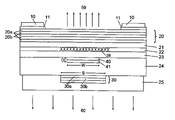
FIG. 1 shows a first embodiment of the invention. The current is supplied through the lower p contact (25), which simultaneously operates as an integrated heat sink, and the n-contacts (10), which may optionally be applied to a highly doped contact layer (11). The light escapes upwards (50) while the heat is removed downwards (60) through the integrated heat sink (25), e.g., onto a copper housing. The active laser region (26) is situated within the active layer (22), which preferably consists of a braced multi-layer structure (Multi-quantum well: MQW structure). The lateral dimensions of the active laser region are determined by the flow of current through the structured tunnel contact or tunnel junction consisting of a highly p-doped layer (40) and a highly n-doped layer (41), which is laterally circular in structure, for example (diameter W), and by the lateral expansion of the current in the layer (23) and the charge carrier diffusion in the active layer (22). The vertical limit of the electrons and holes injected into the active region is provided by the n- and p-doped boundary layers (21) and (23), respectively.
On the n side is the mirror (20) produced epitaxially according to the prior art and consisting for example of a plurality (e.g., 36) of λ/4 pairs of layers of two semiconductor materials (20 a) and (20 b) with different refractive indices. The lower mirror (30) consists of several (e.g., 1.5 or 2.5) pairs of dielectric λ/4 pairs of layers (30 a) and (30 b), such as MgF2 (30 a) and Si (30 b), for example. Its reflectivity is additionally increased by the reflection on the lower interface with the integrated heat sink (25), particularly if the latter consists of highly reflective metals such as gold or silver.
In the vertical direction, the tunnel contact is placed in the minimum amount of the electromagnetic field so that there are no or only very negligible optical losses in the highly doped and absorbent layers (40) and (41). For the same reason the tunnel contact should be as thin as possible; favorable values for the total thickness D are 20 to 60 nm for 1.3 to 1.55 μm VCSEL. The second semiconductor layer (24) on the p side may be (highly) n-doped by virtue of the tunnel contact or may have a gradient in the n doping with lower doping adjacent to the layer (23) and higher doping on the underside towards the mirror (30) and the integrated heat sink (25). In each case there is a blocking npn structure adjacent to the tunnel contact, which blocks the flow of current at this point so that the entire current flows through the tunnel contact into the active layer. The layer (24) should preferably have good thermal conductivity in order to improve and expand the flow of heat from the active region (e.g., to a multiple of the diameter S), thus giving the advantage of reduced overall heating.
Thanks to the low impedance of the n-doped layer (24) the lateral supply of current adjacent to the insulating dielectric mirror (30) may take place without any substantial electric losses and without generating heat. The lateral dimension S of the dielectric mirror is preferably selected to be at least as great as the lateral dimension W of the tunnel contact. It is particularly useful if the dimension S is about 3–8 μm greater than W (typically 2–20 μm for 1.3 μm and 1.55 μm VCSELs), since the lateral expansion of the optical field, as a result of the wave guiding by the amplification and thermal lensing of the active laser region (26), is restricted to roughly the dimension of the active laser region.
FIG. 2 shows a second embodiment of the invention. In contrast to FIG. 1, the manufacturing process is such that the structure of the tunnel contact is imaged in the epitaxy overgrowing into the surface of the layer (24). This results in increased lateral wave guiding which is aligned precisely, in self-adjusting manner, with the tunnel contact and the active region (26). Depending on the course of the process, the imaging of the tunnel contact may be widened or reduced, thus allowing, the lateral limits of the optical field to be influenced over a wide range. This method may be combined with the structural variants described below in order to optimize laser properties.
FIG. 3 shows a third embodiment of the invention. It is clearly emphasized here that the application of an additional highly reflective metallic layer (30 c) onto the dielectric mirror (30) as a whole can produce high reflectivity which in this embodiment does not depend on the properties of the integrated heat sink and contact layer (25).
FIG. 4 shows a fourth embodiment of the invention. In this embodiment the contact resistance to the contact layer (25) on the p side can be reduced by lateral insertion of a highly n-doped intermediate contact layer (70). For example, the layer (24) may consist of thermally highly conductive n-doped InP and the intermediate contact layer (70) may consist of highly n-doped InGaAs, which produces very low contact resistances.
As the n-doped intermediate contact layer according to the FIG. 4 may be a poor conductor of heat, as in the case of InGaAs, FIG. 5 shows a fifth embodiment of the invention in which both low-impedance contact by means of the intermediate contact layer (70) and also a good discharge of heat through the window (71) are made possible by the fact that an intermediate space is provided between the dielectric mirror (30) and the intermediate contact layer (70), through which the heat is able to flow away. The lateral width of the region (71) is therefore preferably greater than the thickness of the layer (24).
FIG. 6 shows three process steps for producing a diffusion barrier according to a first embodiment.
In a first step (a) a diffusion barrier 601 is applied to a first area, while a second area 602 is masked. The diffusion barrier may consist of platinum (Pt), for example. In order to achieve better adhesion to the underlying n-doped semiconductor layer, a layer of titanium may be applied underneath the layer of platinum. Finally, a layer of gold may be applied to the layer of platinum. In this form the diffusion barrier then consists of layers of Ti/Pt/Au.
In a second step (b) a dielectric mirror 603 is applied in the second region 602. A certain overlap with the diffusion barrier 601 may be allowed at the points 605, 606. The advantage of this overlap is that a tight seal can be guaranteed between the dielectric mirror and the diffusion barrier so as to safely rule out any possibility of diffusion from the contact layer into the n-doped semiconductor layer.
Finally, in a third step (c), a layer of gold 604 is applied to the dielectric mirror 603.
FIG. 7 shows three process steps for the preparation of a diffusion barrier according to a second embodiment. The main difference from the process steps according to FIG. 6 is that, in a first process step (a), first of all a dielectric mirror is applied and in a second process step (b) the diffusion barrier 702 is then applied which may in turn consist of the sequence of layers Ti/Pt/Au mentioned above. Then, in a third step (c), a layer of gold 703 is applied to the dielectric mirror. In the process sequence according to FIG. 7, the masking is precisely adjusted so as to prevent diffusion between the dielectric mirror and the n-doped semiconductor layer underneath it, as before.
Table 1, finally, lists some exemplary data for a semiconductor diode according to the invention, the numbers in the first column referring to the reference numerals in the figures.
TABLE 1
Typical data for a semiconductor diode according to
the invention with a wavelength of 1.55 μm. λg
indicates the wavelength corresponding to the band spacing.
Doping Thickness Diameter
No. Material (cm-3) (nm) (μm) Note
10 Ti: 10 nm ca. 530 55 on the
Pt: 20 nm inside
Au: 500 nm 240 on the
outside
11 InGaAs (lattice matched to n = 5 × 10¹⁹ 100 50 on the
InP) inside
250 on the
outside
20 20a InGaAlAs (refractive index n = 2 × 10¹⁸ 111 250 Repeated
approx 3.48) 36 times
20b InAlAs (refractive index n = 2 × 10¹⁸ 121 250
approx 3.2)
21 InAlAs n = 5 × 10¹⁷  50 250
22 InGaAlAs (λg = 1.1 μm): 20 nm Undoped 108 250
InGaAlAs (λg = 1.7 μm): 8 nm
InGaAlAs (λg = 1.1 μm): 7 nm
InGaAlAs (λg = 1.7 μm): 8 nm
InGaAlAs (λg = 1.1 μm): 7 nm
InGaAlAs (λg = 1.7 μm): 8 nm
InGaAlAs (λg = 1.1 μm): 7 nm
InGaAlAs (λg = 1.7 μm): 8 nm
InGaAlAs (λg = 1.1 μm): 7 nm
InGaAlAs (λg = 1.7 μm): 8 nm
InGaAlAs (λg = 1.1 μm): 20 nm
23 InAlAs p = 5 × 10¹⁷  50 250
24 InP n = 1 − 5 × 10¹⁸
25 Ti: 10 nm ca. 50 μm 250
Pt: 20 nm
Au: 50 μm
30 30a MgF2 280  12
30b Si 110  12
40 InGaAlAs (λg = 1.4 μm) p = 1020  20  8
41 InGaAs (lattice matched to n = 1020  20  8
InP)
50 Light exit aperture ca. 50 μm
60 Discharge of heat ca. 250 μm

Claims (27)

1. A semiconductor laser of the surface emitting type, comprising:
an active zone having a pn transition;
a first n-doped semiconductor layer on an n side of the active zone,
a structured tunnel contact on a p side of the active zone which forms a conductive transition to a second n-doped semiconductor layer on the p side of the active zone;
a structured dielectric mirror which is applied to the second n-doped semiconductor layer;
a contact layer which forms a contact with the second n-doped semiconductor layer at points where the dielectric mirror is not applied; and
a diffusion barrier between the contact layer and the second n-doped semiconductor layer, wherein the dielectric mirror laterally partially overlaps the diffusion barrier.
2. A semiconductor laser according to claim 1, comprising an adhesion promoter between the diffusion barrier and the second semiconductor layer.
3. A semiconductor laser according to claim 2, the adhesion promoter comprising a layer of titanium.
4. A semiconductor laser according to claim 1, the diffusion barrier comprising a layer of platinum.
5. A semiconductor laser according to claim 1, further comprising a metallic covering layer between the dielectric mirror and the contact layer for increasing reflectivity.
6. A semiconductor laser according to claim 5, the metallic covering layer located through and between the diffusion barrier and the contact layer.
7. A semiconductor laser according to claim 6, the metallic covering layer comprising gold.
8. A semiconductor laser according to claim 1, the contact layer comprising one of gold and silver.
9. A semiconductor laser according to claim 1, the dielectric mirror having a lower heat resistance than semiconductor materials.
10. A semiconductor laser according to claim 1, wherein the second n-doped semiconductor layer comprises an InP semiconductor.
11. A semiconductor laser according to claim 1, the contact layer having sufficient thickness to act as a heat sink.
12. A semiconductor laser according to claim 11, the contact layer being more than 10 μm thick.
13. A semiconductor laser according to claim 1, wherein light is decoupled on the n side of the active zone.
14. A semiconductor laser according to claim 13, further comprising a substrate removed from the n side of the active zone.
15. A semiconductor laser according to claim 14, the contact layer having sufficient thickness to ensure mechanical stability of the semiconductor laser with the substrate removed from the n side of the active zone.
16. A process for producing a diffusion barrier in a semiconductor laser with an active zone having a pn transition, comprising:
forming a first n-doped semiconductor layer on an n side of the active zone,
forming a structured tunnel contact on a p side of the active zone which forms a conductive transition to a second n-doped semiconductor layer on the p side of the active zone,
applying a diffusion barrier to the second n-doped semiconductor layer;
applying a dielectric mirror to the second n-doped semiconductor layer such that the dielectric mirror laterally partially overlaps the diffusion barrier; and
applying a contact layer at least over the diffusion barrier.
17. A process according to claim 16, wherein applying the dielectric mirror comprises applying the dielectric mirror before the diffusion barrier is applied.
18. A process according to claim 16, wherein applying the dielectric mirror comprises applying the dielectric mirror after the diffusion barrier is applied.
19. A process according to claim 16, further comprising applying an adhesion promoter before the diffusion barrier.
20. A process according to claim 19, wherein applying the adhesion promoter comprises utilizing titanium.
21. A process according to claim 16, the step of applying a diffusion barrier comprising utilizing platinum.
22. A process according to claim 16, wherein applying the contact layer comprises applying a metallic contact layer over an entire surface of the diffusion barrier and the dielectric mirror.
23. A process according to claim 22, wherein applying the metallic contact layer comprises forming the metallic contact layer from one of gold and silver.
24. A process according to claim 22, further comprising applying a metallic covering layer before the contact layer is applied over the dielectric mirror.
25. A process according to claim 22, further comprising applying a metallic covering layer before the contact layer is applied over the entire surface of the dielectric mirror and the diffusion barrier.
26. A process according to claim 24, wherein applying the metallic covering layer comprises forming the metallic covering layer from gold.
27. A semiconductor laser according to claim 1, the dielectric mirror laterally adjoining the diffusion barrier.
US10/468,183 2001-02-15 2002-02-15 Surface-emitting semiconductor laser Expired - Lifetime US7170917B2 (en)

Applications Claiming Priority (3)

Application Number Priority Date Filing Date Title
DE10107349A DE10107349A1 (en) 2001-02-15 2001-02-15 Surface emitting semiconductor laser
DE10107349.6 2001-02-15
PCT/EP2002/001656 WO2002065599A2 (en) 2001-02-15 2002-02-15 Surface-emitting semiconductor laser

Publications (2)

Publication Number Publication Date
US20040179568A1 US20040179568A1 (en) 2004-09-16
US7170917B2 true US7170917B2 (en) 2007-01-30

Family

ID=7674324

Family Applications (1)

Application Number Title Priority Date Filing Date
US10/468,183 Expired - Lifetime US7170917B2 (en) 2001-02-15 2002-02-15 Surface-emitting semiconductor laser

Country Status (12)

Country Link
US (1) US7170917B2 (en)
EP (1) EP1366548B1 (en)
JP (1) JP2004535058A (en)
KR (1) KR100626891B1 (en)
CN (1) CN1263207C (en)
AT (1) ATE294457T1 (en)
CA (1) CA2438341A1 (en)
DE (2) DE10107349A1 (en)
DK (1) DK1366548T3 (en)
ES (1) ES2240725T3 (en)
IL (1) IL157362A0 (en)
WO (1) WO2002065599A2 (en)

Cited By (3)

* Cited by examiner, † Cited by third party
Publication number Priority date Publication date Assignee Title
US20060249738A1 (en) * 2003-10-16 2006-11-09 Markus Ortsiefer Surface-emitting semiconductor laser comprising a structured waveguide
US10033158B1 (en) 2016-12-19 2018-07-24 Osram Opto Semiconductors Gmbh Semiconductor laser, laser assembly and method of making a semiconductor laser
CN114498285A (en) * 2022-01-24 2022-05-13 中国科学院半导体研究所 Semiconductor laser

Families Citing this family (18)

* Cited by examiner, † Cited by third party
Publication number Priority date Publication date Assignee Title
DE10107349A1 (en) 2001-02-15 2002-08-29 Markus-Christian Amann Surface emitting semiconductor laser
DE10147888A1 (en) * 2001-09-28 2003-04-24 Osram Opto Semiconductors Gmbh Optically pumped vertically emitting semiconductor laser
DE10305079B4 (en) * 2002-11-27 2005-04-28 Vertilas Gmbh Method for producing a buried tunnel junction in a surface emitting semiconductor laser and surface emitting semiconductor laser
US6936486B2 (en) * 2002-11-19 2005-08-30 Jdsu Uniphase Corporation Low voltage multi-junction vertical cavity surface emitting laser
ATE333158T1 (en) * 2002-11-27 2006-08-15 Vertilas Gmbh METHOD FOR PRODUCING A BURNED TUNNEL CONTACT IN A SURFACE EMITTING SEMICONDUCTOR LASER
US6870868B2 (en) * 2003-02-18 2005-03-22 Eastman Kodak Company Organic laser having improved linearity
US7372886B2 (en) * 2004-06-07 2008-05-13 Avago Technologies Fiber Ip Pte Ltd High thermal conductivity vertical cavity surface emitting laser (VCSEL)
JP2008198957A (en) * 2007-02-16 2008-08-28 Hitachi Ltd Semiconductor laser device and optical amplification device
US7974328B2 (en) 2007-03-22 2011-07-05 Nec Corporation Surface-emission type semiconductor laser
JP2012119408A (en) * 2010-11-30 2012-06-21 Nippon Telegr & Teleph Corp <Ntt> Semiconductor element, semiconductor optical element, and semiconductor integrated element
KR20130132064A (en) * 2012-05-25 2013-12-04 (주)파이버피아 Vertical cavity surface emitting laser diode
CN106856296B (en) * 2016-12-27 2019-07-05 中国科学院半导体研究所 A kind of long-wavelength vertical cavity surface emitting laser
CN108927601A (en) * 2018-07-18 2018-12-04 张家港市顶峰激光科技有限公司 It is a kind of to carry out material surface levelling means using semiconductor laser beam
US11695093B2 (en) 2018-11-21 2023-07-04 Analog Devices, Inc. Superlattice photodetector/light emitting diode
US12502104B2 (en) 2022-08-31 2025-12-23 Bandwidth10, LTD. Health-monitoring device wit VCSEL
US12514472B2 (en) 2022-08-31 2026-01-06 Bandwidth10, LTD. Health-monitoring measurement and/or monitoring with a smartwatch that includes one or more VCSEL's
US12272924B2 (en) 2022-12-12 2025-04-08 Bandwidth10, LTD. HCG tunable VCSEL system with ASIC for processing information and firmware
US12483003B2 (en) 2022-12-12 2025-11-25 Bandwidth10, LTD. HCG tunable VCSEL with integrated detector in the sacrificial layer

Citations (7)

* Cited by examiner, † Cited by third party
Publication number Priority date Publication date Assignee Title
EP0184117A2 (en) 1984-12-03 1986-06-11 Siemens Aktiengesellschaft Radiation-emitting semiconductor diode having a small-area contact with a larger area surface protection
US5661075A (en) 1995-02-06 1997-08-26 Motorola Method of making a VCSEL with passivation
WO1998007218A1 (en) 1996-08-09 1998-02-19 W.L. Gore & Associates, Inc. Vertical cavity surface emitting laser with tunnel junction
US5831295A (en) * 1995-12-01 1998-11-03 Motorola, Inc. Current confinement via defect generator and hetero-interface interaction
US5936266A (en) * 1997-07-22 1999-08-10 The Board Of Trustees Of The University Of Illinois Semiconductor devices and methods with tunnel contact hole sources
US6052398A (en) 1997-04-03 2000-04-18 Alcatel Surface emitting semiconductor laser
DE10107349A1 (en) 2001-02-15 2002-08-29 Markus-Christian Amann Surface emitting semiconductor laser

Patent Citations (7)

* Cited by examiner, † Cited by third party
Publication number Priority date Publication date Assignee Title
EP0184117A2 (en) 1984-12-03 1986-06-11 Siemens Aktiengesellschaft Radiation-emitting semiconductor diode having a small-area contact with a larger area surface protection
US5661075A (en) 1995-02-06 1997-08-26 Motorola Method of making a VCSEL with passivation
US5831295A (en) * 1995-12-01 1998-11-03 Motorola, Inc. Current confinement via defect generator and hetero-interface interaction
WO1998007218A1 (en) 1996-08-09 1998-02-19 W.L. Gore & Associates, Inc. Vertical cavity surface emitting laser with tunnel junction
US6052398A (en) 1997-04-03 2000-04-18 Alcatel Surface emitting semiconductor laser
US5936266A (en) * 1997-07-22 1999-08-10 The Board Of Trustees Of The University Of Illinois Semiconductor devices and methods with tunnel contact hole sources
DE10107349A1 (en) 2001-02-15 2002-08-29 Markus-Christian Amann Surface emitting semiconductor laser

Non-Patent Citations (6)

* Cited by examiner, † Cited by third party
Title
Liau, Z.L., et al: "A Novel Technique For Gainasp/Inp Buried Heterostructure Laser Fabrication" Applied Physics Letters, American Institute of Physics, New York, US, p. 568-570, Apr. 1, 1982.
Nakagawa, S., et al.: "88° Continuous-Wave Operation Of Apertured, Intracavity Contacted, 1.55 Mum Vertical-Cavity Surface-Emitting Lasers" Applied Physics Letters, American Institute of Physics, New York, US, p. 1337-1339, Mar. 5, 2001.
Ortsiefer, M, et al.: "Low-Threshold Index-Guided 1.5 Mum Long-Wavelenght Vertical-Cavity Surface-Emitting Laser With High Efficiency", Applied Physics Letters, American Institute of Physics, New York, US, p. 2179-2181, Apr. 17, 2000.
Ortsiefer, M, et al: "90° C Continuous-Wave Operation Of 1.83-Mum Vertical-Cavity Surface-Emitting Lasers" IEEE Photonics Technology Letters, IEE Inc., New York, US, pp. 1435-1437, Nov. 2000.
Ortsiefer, M., et al: "Submilliamp Long-Wavelength InP-Based Vertical-Cavity Surface-Emitting Laser With Stable Linear Polarisation" Electronics Letters, IEE Stevenage, p. 1124-1126, Jun. 22, 2000.
Schraud, G, et al: "Substrateless Singlemode Vertical Cavity Surface-Emitting GaAs/GaALAs Laser Diode" Electronics Letters, IEE Stevenage, GB, pp. 238-239, Feb. 3, 1994.

Cited By (5)

* Cited by examiner, † Cited by third party
Publication number Priority date Publication date Assignee Title
US20060249738A1 (en) * 2003-10-16 2006-11-09 Markus Ortsiefer Surface-emitting semiconductor laser comprising a structured waveguide
US7700941B2 (en) * 2003-10-16 2010-04-20 Vertilas Gmbh Surface-emitting semiconductor laser comprising a structured waveguide
US10033158B1 (en) 2016-12-19 2018-07-24 Osram Opto Semiconductors Gmbh Semiconductor laser, laser assembly and method of making a semiconductor laser
CN114498285A (en) * 2022-01-24 2022-05-13 中国科学院半导体研究所 Semiconductor laser
CN114498285B (en) * 2022-01-24 2024-02-06 中国科学院半导体研究所 Semiconductor laser

Also Published As

Publication number Publication date
ES2240725T3 (en) 2005-10-16
CN1263207C (en) 2006-07-05
CA2438341A1 (en) 2002-08-22
EP1366548A2 (en) 2003-12-03
DE50202912D1 (en) 2005-06-02
ATE294457T1 (en) 2005-05-15
DE10107349A1 (en) 2002-08-29
CN1491468A (en) 2004-04-21
US20040179568A1 (en) 2004-09-16
DK1366548T3 (en) 2005-06-27
EP1366548B1 (en) 2005-04-27
JP2004535058A (en) 2004-11-18
KR20030084928A (en) 2003-11-01
IL157362A0 (en) 2004-02-19
WO2002065599A3 (en) 2002-10-24
KR100626891B1 (en) 2006-09-20
WO2002065599A2 (en) 2002-08-22

Similar Documents

Publication Publication Date Title
US7170917B2 (en) Surface-emitting semiconductor laser
US4943970A (en) Surface emitting laser
US5724376A (en) Transparent substrate vertical cavity surface emitting lasers fabricated by semiconductor wafer bonding
US4901327A (en) Transverse injection surface emitting laser
US6687281B2 (en) Double intracavity contacted long-wavelength VCSELs
US20020163950A1 (en) Coupled cavity anti-guided vertical-cavity surface-emitting laser
JPH10321952A (en) Surface-emitting semiconductor laser
JPS61127192A (en) surface emission light emitting device
WO1992000610A1 (en) Quantum well device with control of spontaneous photon emission, and method of manufacturing same
JP2004146833A (en) Electrically pumped vertical cavity surface emitting laser with multiple active regions.
US6904072B2 (en) Vertical cavity surface emitting laser having a gain guide aperture interior to an oxide confinement layer
JP2012505541A (en) Vertical cavity surface emitting laser with improved mode selectivity
JP2000196189A (en) Surface emitting semiconductor laser
GB2347559A (en) Wafer bonded vertical cavity surface emitting lasers
US20060126687A1 (en) Method for producing a buried tunnel junction in a surface-emitting semiconductor laser
US7376163B2 (en) Method for producing a waveguide structure in a surface-emitting semiconductor laser and surface-emitting semiconductor laser
US6977424B1 (en) Electrically pumped semiconductor active region with a backward diode, for enhancing optical signals
Chua et al. Low-threshold InAlGaAs vertical-cavity surface-emitting laser arrays using transparent contacts
JP2024070244A (en) Multi-junction bottom-emitting vertical cavity surface-emitting laser and method for fabricating same
KR940010166B1 (en) Method of manufacturing surface-emitting semiconductor laser diode
JPS6395689A (en) semiconductor light emitting device
JPH03148892A (en) Surface-emission laser oscillator
JPS6212182A (en) semiconductor laser

Legal Events

Date Code Title Description
AS Assignment

Owner name: VERTILAS GMBH, GERMANY

Free format text: ASSIGNMENT OF ASSIGNORS INTEREST;ASSIGNORS:AMANN, MARKUS-CHRISTIAN;ORTSIEFFER, MARKUS;REEL/FRAME:015352/0888

Effective date: 20040323

STCF Information on status: patent grant

Free format text: PATENTED CASE

CC Certificate of correction
FPAY Fee payment

Year of fee payment: 4

FEPP Fee payment procedure

Free format text: PAT HOLDER CLAIMS SMALL ENTITY STATUS, ENTITY STATUS SET TO SMALL (ORIGINAL EVENT CODE: LTOS); ENTITY STATUS OF PATENT OWNER: SMALL ENTITY

FPAY Fee payment

Year of fee payment: 8

MAFP Maintenance fee payment

Free format text: PAYMENT OF MAINTENANCE FEE, 12TH YR, SMALL ENTITY (ORIGINAL EVENT CODE: M2553)

Year of fee payment: 12

AS Assignment

Owner name: SOUND POINT AGENCY LLC, NEW YORK

Free format text: SECURITY INTEREST;ASSIGNORS:LUMILEDS LLC;LUMILEDS HOLDING B.V.;REEL/FRAME:062299/0338

Effective date: 20221230