US7169150B2 - Non-metallic orthopedic plate - Google Patents
Non-metallic orthopedic plate Download PDFInfo
- Publication number
- US7169150B2 US7169150B2 US10/423,712 US42371203A US7169150B2 US 7169150 B2 US7169150 B2 US 7169150B2 US 42371203 A US42371203 A US 42371203A US 7169150 B2 US7169150 B2 US 7169150B2
- Authority
- US
- United States
- Prior art keywords
- plate
- insert
- bone
- openings
- screw
- Prior art date
- Legal status (The legal status is an assumption and is not a legal conclusion. Google has not performed a legal analysis and makes no representation as to the accuracy of the status listed.)
- Expired - Lifetime, expires
Links
Images


Classifications
-
- A—HUMAN NECESSITIES
- A61—MEDICAL OR VETERINARY SCIENCE; HYGIENE
- A61B—DIAGNOSIS; SURGERY; IDENTIFICATION
- A61B17/00—Surgical instruments, devices or methods
- A61B17/56—Surgical instruments or methods for treatment of bones or joints; Devices specially adapted therefor
- A61B17/58—Surgical instruments or methods for treatment of bones or joints; Devices specially adapted therefor for osteosynthesis, e.g. bone plates, screws or setting implements
- A61B17/68—Internal fixation devices, including fasteners and spinal fixators, even if a part thereof projects from the skin
- A61B17/80—Cortical plates, i.e. bone plates; Instruments for holding or positioning cortical plates, or for compressing bones attached to cortical plates
- A61B17/8033—Cortical plates, i.e. bone plates; Instruments for holding or positioning cortical plates, or for compressing bones attached to cortical plates having indirect contact with screw heads, or having contact with screw heads maintained with the aid of additional components, e.g. nuts, wedges or head covers
- A61B17/8042—Cortical plates, i.e. bone plates; Instruments for holding or positioning cortical plates, or for compressing bones attached to cortical plates having indirect contact with screw heads, or having contact with screw heads maintained with the aid of additional components, e.g. nuts, wedges or head covers the additional component being a cover over the screw head
-
- A—HUMAN NECESSITIES
- A61—MEDICAL OR VETERINARY SCIENCE; HYGIENE
- A61B—DIAGNOSIS; SURGERY; IDENTIFICATION
- A61B17/00—Surgical instruments, devices or methods
- A61B17/56—Surgical instruments or methods for treatment of bones or joints; Devices specially adapted therefor
- A61B17/58—Surgical instruments or methods for treatment of bones or joints; Devices specially adapted therefor for osteosynthesis, e.g. bone plates, screws or setting implements
- A61B17/68—Internal fixation devices, including fasteners and spinal fixators, even if a part thereof projects from the skin
- A61B17/80—Cortical plates, i.e. bone plates; Instruments for holding or positioning cortical plates, or for compressing bones attached to cortical plates
-
- A—HUMAN NECESSITIES
- A61—MEDICAL OR VETERINARY SCIENCE; HYGIENE
- A61B—DIAGNOSIS; SURGERY; IDENTIFICATION
- A61B17/00—Surgical instruments, devices or methods
- A61B17/56—Surgical instruments or methods for treatment of bones or joints; Devices specially adapted therefor
-
- A—HUMAN NECESSITIES
- A61—MEDICAL OR VETERINARY SCIENCE; HYGIENE
- A61B—DIAGNOSIS; SURGERY; IDENTIFICATION
- A61B17/00—Surgical instruments, devices or methods
- A61B17/56—Surgical instruments or methods for treatment of bones or joints; Devices specially adapted therefor
- A61B17/58—Surgical instruments or methods for treatment of bones or joints; Devices specially adapted therefor for osteosynthesis, e.g. bone plates, screws or setting implements
- A61B17/68—Internal fixation devices, including fasteners and spinal fixators, even if a part thereof projects from the skin
- A61B17/70—Spinal positioners or stabilisers, e.g. stabilisers comprising fluid filler in an implant
- A61B17/7059—Cortical plates
Definitions
- the present invention relates generally to bone plating systems, and more particularly, to a plating system for use in the treatment of various orthopedic pathologies.
- fixation plates can be useful in stabilizing the upper or lower cervical spine in traumatic, degenerative, tumorous or infectious processes. Moreover, these plates provide the additional benefit of allowing simultaneous neural decompression with immediate stability.
- the plate must provide strong mechanical fixation that can control movement of each vertebral motion segment in six degrees of freedom.
- the plate must also be able to withstand axial loading in continuity with each of the three columns of the spine.
- the plating system must be able to maintain stress levels below the endurance limits of the material, while at the same time exceeding the strength of the anatomic structures or vertebrae to which the plating system is engaged.
- the thickness of the plate must be small to lower its prominence, particularly in the smaller spaces of the cervical spine.
- the screws used to connect the plate to the vertebrae must not loosen over time or back out from the plate.
- the plate should be designed to contact the vertebrae for greater stability.
- the plate must satisfy certain mechanical requirements, it must also satisfy certain anatomic and surgical considerations.
- the cervical plating system must minimize the intrusion into the patient and reduce the trauma to the surrounding soft tissue. It has also been found that optimum plating systems permit the placement of more than one screw in each of the instrumented vertebrae.
- a bone plate comprises a body portion and at least one locking mechanism for engaging the body portion.
- the body portion is made of a radiolucent material, such as a polymer or polyether ether ketone (PEEK), and includes a plurality of attachment mechanism openings for receiving a plurality of attachment mechanisms, such as bone screws.
- the at least one locking mechanism is for securing at least one of the plurality of attachment mechanisms when received into the body portion.
- the bone plate also includes at least one insert affixable with the body portion, the insert for engaging with the locking mechanism.
- the insert may comprise titanium, aluminum, or some other material that is different than the radiolucent material.
- the insert includes a rotation-prevention portion to thereby prevent rotation of the insert in the body portion.
- the insert may also include a metallic material for threadingly engaging with the locking mechanism.
- the insert may be positioned along a longitudinal axis of the body portion to simultaneously engage with a plurality of locking mechanisms.
- a bone plate in another embodiment, comprises a body formed primarily of a first material, wherein the body includes an opening for receiving an attachment mechanism, such as a bone screw.
- the bone plate also comprises an insert having one or more engaging portions, the insert including a second material different from the first material.
- the bone plate may also include a locking mechanism for engaging with the engaging portion. When engaged with the engaging portion, the locking mechanism secures the attachment mechanism in the corresponding opening.
- the first material is radiolucent, and the second material is radio-opaque. Also in some embodiments, the second material is harder than the first material.
- a spinal plating system for promoting fusion between two or more vertebral bodies.
- the spinal plating system includes a plurality of attachment mechanisms, each of the attachment mechanisms having a centerline, and a body formed primarily of a non-metallic radiolucent material.
- the body includes an upper and a lower surface, and a plurality of attachment mechanism openings for receiving the plurality of attachment mechanisms.
- the spinal plating system also includes at least one threaded insert formed primarily of a metallic material, the insert being insertable into the at least one locking mechanism opening, wherein the threaded insert threadably receives the threaded locking mechanism, the threaded locking mechanism having a head that extends above the upper surface of the body.
- Each locking mechanism opening can be situated such that an attachment mechanism received in one of the attachment mechanism openings is lockably held by the threaded locking mechanism.
- FIG. 1 is a top perspective view of an anterior plating system according to one embodiment of the present invention.
- FIG. 2 is a side elevational view of the plating system shown in FIG. 1 .
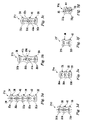
- FIGS. 3 a – 3 g are top elevational views of a fixation plate in accordance with different embodiments of the present invention, provided in different sizes and configuration.
- FIG. 4 is a partial cross-sectional view of a plate according to an embodiment of the present invention with the fixed angle attachment mechanisms disposed within bone holes in a plate and engaged within a vertebra.
- FIG. 5 is an enlarged end cross-sectional view of the plate according to an embodiment of the present invention with variable angle screws disposed in the plate and engaged in a vertebra.
- FIG. 6 a is a bottom perspective view of an anterior plating system according to another embodiment of the present invention.
- FIG. 6 b is a top perspective view of a threaded insert for use with the anterior cervical plating system of FIG. 6 a.
- FIG. 6 c is a side cross-sectional view of the plate shown in FIG. 6 a taken along line 6 c — 6 c as viewed in the direction of the arrows.
- FIG. 7 a is a bottom perspective view of an anterior plating system according to another embodiment of the present invention.
- FIGS. 7 b and 7 c are side cross-sectional views of the plate shown in FIG. 7 a taken along line 7 b — 7 b and 7 c — 7 c , respectively, as viewed in the direction of the arrows.
- FIGS. 1 and 2 One embodiment of a bone plating system or fixation assembly 30 is depicted in FIGS. 1 and 2 .
- the bone plating system 30 is an anterior cervical plate, but it is understood that other plating systems can also benefit from the present invention.
- Other examples include plates or bone repair systems that can be used in the leg, the arm, the foot, the hand, or other parts of the body.
- the plating system includes an elongated plate 31 and one or more bone attachment mechanisms 32 , such as bone screws.
- Other bone attachment mechanisms include bolts, staples, and protrusions that can help to secure the plate in a desired position.
- the attachment mechanisms may be held or retained to the plate 31 by way of one or more locking assemblies 33 .
- the elongated plate 31 is provided with a plurality of openings or holes 34 in a variety of arrangements.
- the plate also can be divided into vertebral level nodes 35 with the attachment mechanisms 32 and openings 34 aligned at each node.
- the plate 31 includes recesses between each of the nodes 35 to reduce the outer contour and size of the plate.
- the reduced width portion between each of the nodes 35 provides an area of reduced material for additional bending of the plate as may be required by the spinal anatomy.
- the plate 31 is constructed, primarily, of a radiolucent material, such as a polymer based resin.
- the plate 31 is constructed substantially from a polyether ether ketone (PEEK) high temperature thermoplastic commercially available by Invibio Biomaterial Solutions of Lancashire, UK under the tradename PEEK-OPTIMA.
- PEEK polyether ether ketone
- CAT computerized axial tomography
- MRI magnetic resonance imaging
- polymers such as PEEK will bow and bend to a limited degree. This flexibility can be used to provide better healing/fusion between the fractured bone or fused vertebral bodies by allowing increased relative motion and avoiding stress shielding.
- the plate 31 can further include one or more bone growth or fusion-promoting elements, such as bone, bone morphogenetic protein (BMP), demineralized bone matrix (DBM), LIM mineralization proteins (LMP), osteogenic pastes, and so forth. It is understood that such fusion-promoting elements are well known by those of ordinary skill in the art.
- BMP bone morphogenetic protein
- DBM demineralized bone matrix
- LMP LIM mineralization proteins
- osteogenic pastes and so forth. It is understood that such fusion-promoting elements are well known by those of ordinary skill in the art.
- the plate 31 can include a rounded upper edge 36 to reduce irritation of surrounding tissue, for example, in a spinal fusion procedure, the rounded upper edge would be in contact with the soft tissue surrounding the spine.
- the rounded upper edge 36 reduces the amount of trauma or irritation that would be experienced by the surrounding soft tissue.
- the bottom surface 37 of the plate 31 is preferably configured to contact and engage the fractured bone or vertebral bodies at each of the instrumented levels of the spine.
- the bottom surface can be textured to enhance its grip on the vertebral body and may have a longitudinal and/or transverse curvature to match the corresponding attachment surface (e.g., the curve of the spine).
- FIGS. 3 a – 3 g several variations of the elongated plate 31 are depicted.
- the bone plating system according to the present embodiment can be readily adapted to fix several fractured bony pieces or vertebrae, of course depending upon the size/length of the plate and the number and arrangement of attachment mechanisms.
- the plate depicted in FIGS. 1 , 2 and 3 a includes five vertebral level nodes 35 a so that the plate can be engaged to five vertebrae of the spine.
- the plate 31 a of FIG. 3 a could be used to fix the vertebrae C2–C6, although the plate also may be used in thoracic, lumbar, and sacral regions of the spine.
- the elongated plates 31 b depicted in FIG. 3 b is sized and configured to span three vertebrae, depending upon the instrumented vertebral levels.
- the plate 31 b includes three vertebral level nodes 35 b, with two nodes at the opposite ends of the plate and one node with attachment mechanisms offset from each other in the middle portion of the plate to accommodate variation in vertebral anatomy.
- FIG. 3 c A modification of the plate 31 b is depicted in FIG. 3 c.
- the plate 31 c includes three nodes 35 c, with the nodes on the opposite side of the middle portion of the plate being directly aligned at the same vertebral level.
- the plates of FIGS. 3 d – 3 e namely plates 31 d and 31 e, are similar to the plate 31 c although their lengths are progressively shorter to accommodate varying vertebral body height.
- the last two plates 31 f and 31 g, in FIGS. 3 f – 3 g, respectively, provide for instrumentation of two vertebral levels, each having two nodes 35 f and 35 g, respectively.
- the elongated plates 31 a – 31 g can provide a variety of hole patterns at each of the nodes 35 a – 35 g. These hole patterns can provide for at least two attachment mechanisms (e.g., screws) to be engaged into each respective bony portion (e.g., vertebral body). As discussed above, it has been found that the placement of two or more screws in each vertebral body improves the stability of the construct.
- attachment mechanisms e.g., screws
- the present embodiments may also provide a mechanism for locking the attachment mechanisms to the elongated plate to prevent backout, loosening, or other dis-engagement of the attachment mechanisms. Consequently, in a further aspect of the embodiments, various openings hole patterns may be provided.
- One pattern is an end hole pattern 38 , as shown at the ends of plate 31 in FIG. 1 and plate 31 a in FIG. 3 a.
- two screw holes 34 are laterally disposed at a single node 35 a.
- a single locking assembly may be disposed between the two screw holes 34 and configured to lock attachment mechanisms disposed within the plate 31 a.
- the locking assembly can be a machine screw that engages with threads in the plate 31 a, or can be a self-tapping screw that cuts through the plate as it is advanced therein.
- Other types of locking assemblies include a rotatable disk, lever, or rivet shaped to selectively allow one or more attachment mechanisms to be inserted and locked; a deformable portion (e.g., a washer) that selectively allow one or more attachment mechanisms to be inserted and locked; strap/tie mechanisms that can be used to selectively tie down one or more attachment mechanisms; and a sliding member for moving between different positions to selectively allow one or more attachment mechanisms to be inserted and locked.
- a similar arrangement can be provided by the middle hole pattern 39 in which two screw holes are situated at a single vertebral level.
- a locking assembly can be disposed between the two attachment mechanism holes and configured to lock the respective attachment mechanisms.
- the present embodiment further contemplates a plate carrying four-attachment mechanism patterns.
- the four-hole pattern 40 illustrated in FIG. 1 and FIGS. 3 a and 3 d provides for four bone screws holes in a diamond pattern.
- a single locking assembly 33 can be centrally disposed between all of the attachment mechanism holes so that attachment mechanisms within the respective holes are simultaneously locked by the single locking assembly.
- two such four-hole patterns 40 are provided in the five node plate 31 a of FIG. 3 a.
- two such four-hole patterns 40 are provided in the three-node plate 31 d of FIG. 3 d. only a single four-hole pattern 40 is required.
- the four-hole pattern 40 provides a great degree of flexibility to the surgeon in determining how many attachment mechanisms 32 will be engaged into a single vertebra, and in what arrangement.
- two screws are situated in the laterally opposite screw holes at the vertebral level node 35 .
- attachment mechanisms could be placed in the longitudinally opposite screw holes oriented along the length of the plate 31 a.
- Other arrangements contemplate attachment mechanisms being placed in immediately adjacent screw holes 34 , or placing three attachment mechanisms in three of the holes of the four-hole pattern 40 . Again, the selection of attachment mechanisms and their arrangement can be left to the surgeon and will be based upon the type of correction or fixation required and the anatomy of bony member being addressed.
- a further arrangement for attachment mechanisms is provided by the four-hole cluster 41 depicted in FIGS. 3 b and 3 c.
- the four-hole cluster 41 in plate 31 b two hole pairs 41 a and 41 b are provided.
- Each of the hole pairs may include its own locking assembly to lock the two attachment mechanisms (e.g., screws) into the screw bores of the respective hole pairs.
- the orientation of the particular hole pairs provides one screw hole from each pair generally laterally relative to each other in a single bony portion (e.g., vertebra).
- the other of the attachment mechanism holes in each respective pair is longitudinally offset from the central screw holes, being disposed closer to the ends of the plate 31 b.
- each of the screw holes in the four-hole cluster 41 is generally oriented over or slightly offset from a single vertebra. The surgeon then has the option to selected any of the screw holes in the two hole pairs 41 a or 41 b that is optimally aligned over the vertebra.
- the plate 31 C which includes a four-hole cluster 42 .
- the four-hole cluster 42 includes two hole pairs 42 a and 42 b, in a manner similar to the four-hole cluster 41 of FIG. 3 b; however in this case, the hole pairs are arranged closer to each other, principally because the plate 31 c is shorter than the plate 31 b.
- the locking assemblies are provided to lock only a pair of attachment mechanism holes rather than all four holes with a single locking assembly.
- the invention further contemplates a three-hole pattern, such as pattern 43 provided in the plate 31 f in FIG. 3 f.
- a single locking assembly is used to fix three attachment mechanisms within the respective screw holes.
- a five-hole pattern 44 is provided on plate 31 g, as shown in FIG. 3 g.
- a single hole is arranged centrally between four outlying holes.
- Two locking assemblies 33 are provided to lock a pair of the outlying four screw holes together with the central hole. In this configuration, the central hole is held in place by two locking assemblies, while each of the outlying pair of holes is held in place by a single locking assembly.
- fixation plate assembly 30 is illustrated using, for the sake of example, bone screws for affixing to a vertebral body V.
- a pair of fixed angle screws 50 are disposed within respective bores 34 so that the threaded shanks 51 project beyond the lower surface 37 of the plate 31 and into the vertebral body V.
- the threaded shank is preferably configured to engage the cortical and cancellous bone of the vertebral body V.
- the intermediate portion 52 of the fixed angle screw 50 extends through the cylindrical bore 77 of the screw holes 34 .
- the spherical surface 57 of the head 54 of the screw contacts the spherical recess 75 of the screw hole 34 as the fixed angle screw 50 is threaded into the vertebral body V.
- the locking assembly 33 is tightened onto the heads 54 of the two attachment mechanisms 50 .
- a locking mechanism 85 such as a locking screw, is threaded into the bore 70 to draw the washer 90 into contact with the screw heads.
- the bore 70 is already tapped, although in other embodiments the locking mechanism 85 may be a self tapping screw.
- locking mechanism 85 include a disk, lever, rivet, or other mechanical structure configured or shaped to selectively allow one or more attachment mechanisms to be inserted and/or locked; a deformable portion (e.g., a washer) that selectively allow one or more attachment mechanisms to be inserted and/or locked; strap/tie mechanisms that can be used to selectively tie down one or more attachment mechanisms; and a sliding member for moving between different positions to selectively allow one or more attachment mechanisms to be inserted and/or locked.
- a disk, lever, rivet, or other mechanical structure configured or shaped to selectively allow one or more attachment mechanisms to be inserted and/or locked
- a deformable portion e.g., a washer
- strap/tie mechanisms that can be used to selectively tie down one or more attachment mechanisms
- a sliding member for moving between different positions to selectively allow one or more attachment mechanisms to be inserted and/or locked.
- the convex surface 92 seats against the spherical surface 57 of the attachment mechanism heads 54 to firmly seat the screw heads within the plate spherical recess 75 .
- the locking washer 90 can advance sufficiently far into the locking recess 71 to rest substantially flush with the top surfaces 56 of the attachment mechanisms 50 .
- the locking assembly 33 can be loosely fixed on the plate 31 so that the surgeon does not have to attach the locking assembly when the plate is engaged to a vertebra or other bony member.
- the locking mechanism 85 is a screw that is pre-threaded through the locking washer 90 and into the tapped bore 70 until about three or fewer threads of the locking screw project below the bottom surface 37 of the plate. The locking screw 85 is then staked at the thread furthest from the plate so that the screw cannot be removed or backed out through the tapped bore 70 .
- the locking screw 85 can be advanced further through the bore 70 —when it is necessary to enable the locking assembly 33 .
- the sharp point 86 a of the locking screw 85 is preferably configured to penetrate the cortical bone. With the locking screw staked to the plate, the sharp point 86 a will penetrate the vertebra V when the plate 31 is initially positioned on the bone. In this instance, the locking screw 85 helps locate and temporarily stabilize the plate on the vertebra V as the attachment mechanisms 50 are implanted into the bone. This temporary location feature provided by the locking screw 85 can also be used when a drill guide is used to drill and tap the vertebra to receive the attachment mechanisms 50 .
- the locking assembly 33 can be configured so that the washer 90 can be moved clear of the screw holes 34 when the locking screw 85 is staked to the plate 31 . Thus, even with the locking assembly 33 in its loosened position, the attachment mechanisms 50 , 60 can still be inserted into the screw holes 34 .
- variable angle attachment mechanism 60 The use of the variable angle attachment mechanism 60 is depicted in FIG. 5 .
- the locking assembly 33 functions as described above to lock the heads 64 of the variable angle screws 60 within the plate 31 .
- the convex surface 92 of the washer 90 contacts and applies pressure to the spherical surfaces 67 of the respective attachment mechanisms 60 .
- the intermediate portion 62 does not fit snugly within the cylindrical bore 77 of the screw holes 34 .
- the attachment mechanism 60 can still be angulated relative to the plate and to the axis of the spherical recess 75 and cylindrical bore 77 .
- the degree of angulation is restricted by the difference in diameters between the cylindrical bore 77 and the intermediate portion 62 of the variable angle screw 60 .
- the relative diameters permit angulation of up to 20° from the axis 75 a of the recess 75 and bore 77 .
- variable angle capability of the screw 60 allows the surgeon to place the attachment mechanism within the vertebra at any angle within the defined angulation limits (20° in one specific embodiment).
- the variable angle screw 60 provides greater flexibility than does the fixed angle screw 50 for orienting the attachment mechanism relative to the anatomy of the vertebra.
- this variable angle capability allows a limited degree of micro-motion between the screw and the plate when the fixation assembly 30 is implanted within a patient.
- the variable angle screw 60 accommodates this relative movement by pivoting within the spherical recess 75 .
- the fixed angle screw 50 prevents this relative movement.
- the choice between using a fixed or a variable angle screw can be left to the surgeon depending upon the pathology being treated.
- the fixation plate assembly 30 according to the present embodiment allows this choice to be made at any point during the surgical procedure.
- the plating system 30 of FIGS. 1–5 include many benefits.
- a non-metallic substance such as PEEK
- the plate 31 obtains a degree of flexibility, when compared to metallic plates, while still providing a strong mechanical fixation that can control movement of each vertebral motion segment in six degrees of freedom.
- the plating system 30 is also be able to withstand axial loading in continuity with each of the three columns of the spine.
- the plating system 30 is able to maintain stress levels below the endurance limits of the PEEK material, while at the same time exceeding the strength of the anatomic structures or vertebrae to which the plating system is engaged.
- the thickness of the plate 31 is relatively small, thereby lowering its prominence, particularly in the smaller spaces of the cervical spine.
- the PEEK material allows locking screws to be self-tapped, as contrasted with metallic plates. And, the flexible properties of the PEEK material help to prevent attachment mechanisms from loosening or backing out from the plate 31 and the vertebral bodies.
- plate 31 h is similar to plate 31 f ( FIG. 3 f ) with the inclusion of a metallic insert 100 .
- the metallic insert is made of titanium aluminum, or ceramic, although other materials can also be used.
- the metallic insert 100 is used for part of the locking assembly 33 to provide an improved interface for receiving and securing the locking screw 85 .
- the metallic insert 100 includes an oval shaped portion 102 and a cylindrical portion 104 .
- the cylindrical portion 104 includes a threaded interior wall 106 for receiving and threadingly engaging with the locking mechanism 85 .
- the metallic insert 100 is pressed into the plate 31 h, preferably when the plate is in a more malleable state.
- the plating system 30 of FIGS. 6 a – 6 c include many benefits.
- the metallic inserts 100 provide extra strength for the locking assemblies 33 .
- the metallic inserts 100 are easily threaded, so that the locking mechanism 85 can be of a very tight manufacture (e.g., a tightly threaded screw as compared to a self-tapping screw).
- the oval shaped portion 102 prevents any rotation of the insert 100 when the locking mechanism 85 is being inserted into or removed from the plating system 30 .
- the oval shaped portion 102 prevents the insert from being removed in a direction opposite to the bottom surface 37 of the plate 31 .
- plate 31 i is similar to plate 31 e ( FIG. 3 e ) with the inclusion of a metallic insert 110 .
- the metallic insert is made of titanium or aluminum, although other materials can also be used.
- the metallic insert 110 extends along a longitudinal axis of the plate 31 i, thereby stiffening and strengthening the plate and reducing an amount of bow that would otherwise occur.
- the metallic insert 110 also provides anti-compression strength along its longitudinal axis.
- the metallic insert 110 provides one or more threaded interior walls 112 for receiving and threadingly engaging with screw-type locking mechanisms 85 .
- the extended shape of the metallic insert 110 prevents any rotation of the insert 100 when the locking mechanism 85 is being inserted into or removed from the plating system 30 .
- the metallic insert 110 is illustrated as a single unit, it may be comprised of multiple units.
- the metallic insert 110 is formed as a dove tail, with an upper surface (as shown in FIG. 7 c ) that is larger than its lower surface.
- the dove tail shape of the metallic insert fits like a “key” into a corresponding slot 114 of the plate 31 i.
- the dove tail shape also allows the insert 110 to be slid into the plate 31 i, so that one or more of the threaded portions of the insert are aligned with one or more of the bores 70 .
- a pin 116 may also (or alternatively) be used to secure the metallic insert 110 into the plate. It is known that there are many different ways to secure the metallic insert 110 to the plate 31 i, and the locking screws 85 themselves can be the sole source of securement.
- the plating system 30 of FIGS. 7 a – 7 c include many benefits.
- the metallic inserts 110 provide extra strength for several different locking screws 85 .
- a single metallic insert 110 can easily be slid into the plate 31 i, thereby making manufacturing easier.
- several metallic plates e.g., one for each locking screw 85
- one or more visualization windows can be made in the plate 31 to facilitate the visual placement of the plating system by a surgeon.
- features illustrated and discussed above with respect to some embodiments can be combined with features illustrated and discussed above with respect to other embodiments. Accordingly, all such modifications are intended to be included within the scope of this invention.
Landscapes
- Health & Medical Sciences (AREA)
- Orthopedic Medicine & Surgery (AREA)
- Life Sciences & Earth Sciences (AREA)
- Surgery (AREA)
- Neurology (AREA)
- Heart & Thoracic Surgery (AREA)
- Engineering & Computer Science (AREA)
- Biomedical Technology (AREA)
- Nuclear Medicine, Radiotherapy & Molecular Imaging (AREA)
- Medical Informatics (AREA)
- Molecular Biology (AREA)
- Animal Behavior & Ethology (AREA)
- General Health & Medical Sciences (AREA)
- Public Health (AREA)
- Veterinary Medicine (AREA)
- Surgical Instruments (AREA)
- Prostheses (AREA)
- Materials For Medical Uses (AREA)
Abstract
Description
Claims (11)
Priority Applications (10)
| Application Number | Priority Date | Filing Date | Title |
|---|---|---|---|
| US10/423,712 US7169150B2 (en) | 2003-04-25 | 2003-04-25 | Non-metallic orthopedic plate |
| EP04760226A EP1622528B1 (en) | 2003-04-25 | 2004-03-31 | Orthopedic plate with insert |
| AU2004233785A AU2004233785B2 (en) | 2003-04-25 | 2004-03-31 | Non-metallic orthopedic plate |
| CNA200480013593XA CN1791365A (en) | 2003-04-25 | 2004-03-31 | Non-metallic orthopedic plate |
| CA002523305A CA2523305A1 (en) | 2003-04-25 | 2004-03-31 | Non-metallic orthopedic plate |
| JP2006509597A JP4564487B2 (en) | 2003-04-25 | 2004-03-31 | Non-metallic orthopedic plate |
| PCT/US2004/010093 WO2004096068A1 (en) | 2003-04-25 | 2004-03-31 | Non-metallic orthopedic plate |
| AT04760226T ATE517583T1 (en) | 2003-04-25 | 2004-03-31 | ORTHOPEDIC PLATE WITH INSERT |
| KR1020057020326A KR101074180B1 (en) | 2003-04-25 | 2005-10-25 | Nonmetal Orthopedic Plate |
| US11/668,292 US8617222B2 (en) | 2003-04-25 | 2007-01-29 | Non-metallic orthopedic plate |
Applications Claiming Priority (1)
| Application Number | Priority Date | Filing Date | Title |
|---|---|---|---|
| US10/423,712 US7169150B2 (en) | 2003-04-25 | 2003-04-25 | Non-metallic orthopedic plate |
Related Child Applications (1)
| Application Number | Title | Priority Date | Filing Date |
|---|---|---|---|
| US11/668,292 Continuation US8617222B2 (en) | 2003-04-25 | 2007-01-29 | Non-metallic orthopedic plate |
Publications (2)
| Publication Number | Publication Date |
|---|---|
| US20040215195A1 US20040215195A1 (en) | 2004-10-28 |
| US7169150B2 true US7169150B2 (en) | 2007-01-30 |
Family
ID=33299191
Family Applications (2)
| Application Number | Title | Priority Date | Filing Date |
|---|---|---|---|
| US10/423,712 Expired - Lifetime US7169150B2 (en) | 2003-04-25 | 2003-04-25 | Non-metallic orthopedic plate |
| US11/668,292 Expired - Fee Related US8617222B2 (en) | 2003-04-25 | 2007-01-29 | Non-metallic orthopedic plate |
Family Applications After (1)
| Application Number | Title | Priority Date | Filing Date |
|---|---|---|---|
| US11/668,292 Expired - Fee Related US8617222B2 (en) | 2003-04-25 | 2007-01-29 | Non-metallic orthopedic plate |
Country Status (9)
| Country | Link |
|---|---|
| US (2) | US7169150B2 (en) |
| EP (1) | EP1622528B1 (en) |
| JP (1) | JP4564487B2 (en) |
| KR (1) | KR101074180B1 (en) |
| CN (1) | CN1791365A (en) |
| AT (1) | ATE517583T1 (en) |
| AU (1) | AU2004233785B2 (en) |
| CA (1) | CA2523305A1 (en) |
| WO (1) | WO2004096068A1 (en) |
Cited By (52)
| Publication number | Priority date | Publication date | Assignee | Title |
|---|---|---|---|---|
| US20050228387A1 (en) * | 2004-04-08 | 2005-10-13 | Paul David C | Load distribution crown |
| US20060167456A1 (en) * | 2004-12-21 | 2006-07-27 | Packaging Service Corporation Of Kentucky | Cervical plate system |
| US20070250173A1 (en) * | 2003-02-12 | 2007-10-25 | Warsaw Orthopedic, Inc. | Revisable Prosthetic Device |
| US7306605B2 (en) | 2003-10-02 | 2007-12-11 | Zimmer Spine, Inc. | Anterior cervical plate |
| US20080033437A1 (en) * | 2003-04-25 | 2008-02-07 | Warsaw Orthopedic, Inc. | Non-Metallic Orthopedic Plate |
| US20080097445A1 (en) * | 2006-10-23 | 2008-04-24 | Weinstein Robert B | Bone fixation system |
| US20080177263A1 (en) * | 2006-10-24 | 2008-07-24 | Aesculap Implant Systems, Inc | Dynamic stabilization device for anterior lower lumbar vertebral fusion |
| US20090024171A1 (en) * | 2007-07-19 | 2009-01-22 | Vincent Leone | Anatomical Anterior Vertebral Plating System |
| USD603505S1 (en) | 2008-07-03 | 2009-11-03 | Theken Spine, Llc | Cervical plate |
| USD603511S1 (en) | 2008-07-03 | 2009-11-03 | Theken Spine, Llc | Cervical plate |
| USD603504S1 (en) | 2008-07-03 | 2009-11-03 | Theken Spine, Llc | Cervical plate |
| USD603509S1 (en) | 2008-07-03 | 2009-11-03 | Theken Spine, Llc | Cervical plate |
| USD603503S1 (en) | 2008-07-03 | 2009-11-03 | Theken Spine, Llc | Cervical plate |
| USD603508S1 (en) | 2008-07-03 | 2009-11-03 | Theken Spine, Llc | Cervical plate |
| USD603510S1 (en) | 2008-07-03 | 2009-11-03 | Theken Spine, Llc | Cervical plate |
| USD603507S1 (en) | 2008-07-03 | 2009-11-03 | Theken Spine, Llc | Cervical plate |
| USD603506S1 (en) | 2008-07-03 | 2009-11-03 | Theken Spine, Llc | Cervical plate |
| USD603963S1 (en) | 2008-07-03 | 2009-11-10 | Theken Spine, Llc | Cervical plate |
| USD603961S1 (en) | 2008-07-03 | 2009-11-10 | Theken Spine, Llc | Cervical plate |
| USD603962S1 (en) | 2008-07-03 | 2009-11-10 | Theken Spine, Llc | Cervical plate |
| USD603964S1 (en) | 2008-07-03 | 2009-11-10 | Theken Spine, Llc | Cervical plate |
| US20090299369A1 (en) * | 2008-06-02 | 2009-12-03 | Skeletal Dynamics Llc | Hybrid Orthopedic Implant |
| US20090326580A1 (en) * | 2008-06-25 | 2009-12-31 | Anderson Mark E | Spinal fixation device |
| US20100063550A1 (en) * | 2008-09-11 | 2010-03-11 | Innovasis, Inc, | Radiolucent screw with radiopaque marker |
| US20100114175A1 (en) * | 2006-04-25 | 2010-05-06 | Warsaw Orthopedic, Inc. | Facet Fusion Implants and Methods of Use |
| US7766911B1 (en) | 2002-07-05 | 2010-08-03 | Theken Spine, Llc | Fixed and variable locking fixation assembly |
| US20100217393A1 (en) * | 2009-02-20 | 2010-08-26 | Theofilos Charles S | Interbody fusion system with intervertebral implant retention assembly |
| US20110022096A1 (en) * | 2009-07-24 | 2011-01-27 | Spinal USA LLC | Bone plate system and methods of using the same |
| US20110022097A1 (en) * | 2009-07-24 | 2011-01-27 | Spinal USA LLC | Bone plate screw-blocking systems and methods |
| US20110054542A1 (en) * | 2009-08-31 | 2011-03-03 | Warsaw Orthopedic, Inc. | System with integral locking mechanism |
| US20110060365A1 (en) * | 2009-09-10 | 2011-03-10 | Innovasis, Inc. | Radiolucent stabilizing rod with radiopaque marker |
| US20110172712A1 (en) * | 2004-06-17 | 2011-07-14 | Uriel Hiram Chee | Facet joint fusion devices and methods |
| US20110172666A1 (en) * | 2010-01-08 | 2011-07-14 | Heilman Benjamin P | Variable angle locking screw |
| USD643121S1 (en) | 2010-05-27 | 2011-08-09 | Ebi, Llc | Orthopedic wrist spanning bone plate |
| US20110218570A1 (en) * | 2010-03-08 | 2011-09-08 | Innovasis, Inc. | Radiolucent bone plate with radiopaque marker |
| USD646785S1 (en) | 2010-05-27 | 2011-10-11 | Ebi, Llc | Orthopedic volar bone plate |
| US20120277748A1 (en) * | 2011-04-28 | 2012-11-01 | Warsaw Orthopedic, Inc. | Bone plate |
| US8506608B2 (en) | 2009-03-24 | 2013-08-13 | Douglas Cerynik | Orthopedic fixation device with bioresorbable layer |
| US8728129B2 (en) | 2011-01-07 | 2014-05-20 | Biomet Manufacturing, Llc | Variable angled locking screw |
| US20140163682A1 (en) * | 2012-12-11 | 2014-06-12 | Expandable Vertebral Implant | Expandable Vertebral Implant |
| US8808333B2 (en) | 2009-07-06 | 2014-08-19 | Zimmer Gmbh | Periprosthetic bone plates |
| US8845697B2 (en) | 2011-04-01 | 2014-09-30 | DePuy Synthes Products, LLC | Posterior vertebral plating system |
| US9468479B2 (en) | 2013-09-06 | 2016-10-18 | Cardinal Health 247, Inc. | Bone plate |
| US9474560B2 (en) | 2004-04-08 | 2016-10-25 | Globus Medical, Inc | Load distribution crown |
| USD779065S1 (en) | 2014-10-08 | 2017-02-14 | Nuvasive, Inc. | Anterior cervical bone plate |
| US10537666B2 (en) | 2015-05-18 | 2020-01-21 | Stryker European Holdings I, Llc | Partially resorbable implants and methods |
| US10603182B2 (en) | 2015-01-14 | 2020-03-31 | Stryker European Holdings I, Llc | Spinal implant with fluid delivery capabilities |
| US10835388B2 (en) | 2017-09-20 | 2020-11-17 | Stryker European Operations Holdings Llc | Spinal implants |
| US11000386B2 (en) | 2015-01-14 | 2021-05-11 | Stryker European Holdings I, Llc | Spinal implant with porous and solid surfaces |
| US11026726B2 (en) | 2012-06-29 | 2021-06-08 | K2M, Inc. | Minimal-profile anterior cervical plate and cage apparatus and method of using same |
| US11389209B2 (en) | 2019-07-19 | 2022-07-19 | Medos International Sarl | Surgical plating systems, devices, and related methods |
| US11744619B2 (en) | 2018-04-06 | 2023-09-05 | K2M, Inc. | Faceted bone plate |
Families Citing this family (77)
| Publication number | Priority date | Publication date | Assignee | Title |
|---|---|---|---|---|
| US8105367B2 (en) | 2003-09-29 | 2012-01-31 | Smith & Nephew, Inc. | Bone plate and bone plate assemblies including polyaxial fasteners |
| US8118838B2 (en) * | 2004-12-13 | 2012-02-21 | Kyphon Sarl | Inter-cervical facet implant with multiple direction articulation joint and method for implanting |
| US7591851B2 (en) | 2004-12-13 | 2009-09-22 | Kyphon Sarl | Inter-cervical facet implant and method |
| US7763050B2 (en) * | 2004-12-13 | 2010-07-27 | Warsaw Orthopedic, Inc. | Inter-cervical facet implant with locking screw and method |
| WO2006133086A2 (en) * | 2005-06-03 | 2006-12-14 | Southern Spine, Llc | Surgical stabilization system |
| US8382807B2 (en) | 2005-07-25 | 2013-02-26 | Smith & Nephew, Inc. | Systems and methods for using polyaxial plates |
| EP1919385B1 (en) | 2005-07-25 | 2014-08-20 | Smith & Nephew, Inc. | Polyaxial plates |
| US8486070B2 (en) | 2005-08-23 | 2013-07-16 | Smith & Nephew, Inc. | Telemetric orthopaedic implant |
| US20070233113A1 (en) * | 2005-09-16 | 2007-10-04 | Small Bone Innovations, Inc. | Condylar plate |
| DE202005015975U1 (en) | 2005-10-10 | 2007-02-08 | Synthes Gmbh | target device |
| US7887595B1 (en) | 2005-12-05 | 2011-02-15 | Nuvasive, Inc. | Methods and apparatus for spinal fusion |
| US7641675B2 (en) * | 2006-03-08 | 2010-01-05 | Warsaw Orthopedic, Inc. | Flexible bone plates and methods for dynamic spinal stabilization |
| US20070213705A1 (en) * | 2006-03-08 | 2007-09-13 | Schmid Peter M | Insulated needle and system |
| US7998180B2 (en) * | 2006-04-28 | 2011-08-16 | Warsaw Orthopedic, Inc. | Radiolucent bone plate systems and methods of use |
| US8114162B1 (en) | 2006-08-09 | 2012-02-14 | Nuvasive, Inc. | Spinal fusion implant and related methods |
| USD708747S1 (en) | 2006-09-25 | 2014-07-08 | Nuvasive, Inc. | Spinal fusion implant |
| US8066750B2 (en) * | 2006-10-06 | 2011-11-29 | Warsaw Orthopedic, Inc | Port structures for non-rigid bone plates |
| US8062341B2 (en) * | 2006-10-18 | 2011-11-22 | Globus Medical, Inc. | Rotatable bone plate |
| US20080154312A1 (en) * | 2006-12-12 | 2008-06-26 | Dennis Colleran | Active settling plate with elastomeric members and method of use |
| US20080147125A1 (en) * | 2006-12-12 | 2008-06-19 | Dennis Colleran | Active Settling Plate and Method of Use |
| US20080172092A1 (en) * | 2007-01-12 | 2008-07-17 | Paul Edward Kraemer | System and method for spinal instrumentation |
| DE202007001585U1 (en) | 2007-01-30 | 2007-05-10 | Zrinski Ag | Plate implant for use during osteosynthesis, has thread and head cooperating with connecting unit and longitudinal borehole respectively, such that effect is produced between head and borehole and between connecting and retainer units |
| US8628560B2 (en) * | 2007-03-08 | 2014-01-14 | DePuy Synthes Products, LLC | Orthopaedic instrumentation with integral load-bearing members |
| CN101327153B (en) * | 2007-06-19 | 2010-12-01 | 上海交通大学附属第六人民医院 | Thoracic and lumbar vertebral posterior prosthesis |
| FR2917596B1 (en) * | 2007-06-21 | 2010-06-18 | Newdeal | FASTENING KIT FOR MEDICAL OR SURGICAL USE |
| US8668725B2 (en) * | 2007-07-13 | 2014-03-11 | Southern Spine, Llc | Bone screw |
| WO2009018365A1 (en) | 2007-08-01 | 2009-02-05 | Jeffrey Halbrecht | Method and system for patella tendon realignment |
| US8430882B2 (en) * | 2007-09-13 | 2013-04-30 | Transcorp, Inc. | Transcorporeal spinal decompression and repair systems and related methods |
| US20090138092A1 (en) * | 2007-11-28 | 2009-05-28 | Johnston Brent W | Therapeutic Structures for Utilization in Temporomandibular Joint Replacement Systems |
| GB2457673A (en) * | 2008-02-20 | 2009-08-26 | Surgicraft Ltd | Spinal implant |
| JP5599806B2 (en) | 2008-10-15 | 2014-10-01 | スミス アンド ネフュー インコーポレーテッド | Composite in-house fixator |
| US8795340B2 (en) | 2008-11-07 | 2014-08-05 | Globus Medical, Inc. | Vertical inline plate |
| US20100137916A1 (en) * | 2008-12-03 | 2010-06-03 | Warsaw Orthopedic, Inc., An Indiana Corporation | Spinal plates for stabilizing segments |
| CN116570353A (en) | 2009-08-27 | 2023-08-11 | 铸造有限责任公司 | A device used to change the load between the patella and femur in the knee joint and to treat disorders of the hip joint |
| US9278004B2 (en) | 2009-08-27 | 2016-03-08 | Cotera, Inc. | Method and apparatus for altering biomechanics of the articular joints |
| US9668868B2 (en) | 2009-08-27 | 2017-06-06 | Cotera, Inc. | Apparatus and methods for treatment of patellofemoral conditions |
| US10349980B2 (en) | 2009-08-27 | 2019-07-16 | The Foundry, Llc | Method and apparatus for altering biomechanics of the shoulder |
| US9861408B2 (en) | 2009-08-27 | 2018-01-09 | The Foundry, Llc | Method and apparatus for treating canine cruciate ligament disease |
| SM200900081B (en) * | 2009-10-05 | 2010-11-12 | Hit Medica S P A | Plate system for osteosynthesis with angular stability multi-axial screws in polymeric material. |
| FR2959927B1 (en) * | 2010-05-17 | 2013-07-12 | Medicrea International | RETENTION SYSTEM OF AN ANCHORING DEVICE ON AN IMPLANTABLE PIECE |
| US8940030B1 (en) | 2011-01-28 | 2015-01-27 | Nuvasive, Inc. | Spinal fixation system and related methods |
| CN103717179B (en) | 2011-06-15 | 2017-08-08 | 史密夫和内修有限公司 | Variable Angle Locking Implants |
| JP2014525776A (en) * | 2011-06-30 | 2014-10-02 | ロリオ,モーガン,パッカード | Spine plate and method of using the same |
| US8668723B2 (en) | 2011-07-19 | 2014-03-11 | Neurostructures, Inc. | Anterior cervical plate |
| US9468466B1 (en) | 2012-08-24 | 2016-10-18 | Cotera, Inc. | Method and apparatus for altering biomechanics of the spine |
| US9629664B2 (en) | 2014-01-20 | 2017-04-25 | Neurostructures, Inc. | Anterior cervical plate |
| US9486250B2 (en) | 2014-02-20 | 2016-11-08 | Mastros Innovations, LLC. | Lateral plate |
| US9814503B1 (en) | 2014-04-14 | 2017-11-14 | Avanti Orthopaedics, LLC | Load sharing bone plate |
| US11452553B1 (en) | 2014-04-14 | 2022-09-27 | Avanti Orthopaedics, LLC | Load sharing bone plate |
| US11937858B2 (en) | 2014-04-14 | 2024-03-26 | Avanti Orthopaedics, LLC | Load sharing bone plate |
| US10517657B1 (en) | 2014-04-14 | 2019-12-31 | Avanti Orthopaedics, LLC | Load sharing bone plate |
| CN105125271A (en) * | 2015-09-16 | 2015-12-09 | 常州市康辉医疗器械有限公司 | Anatomical locking and pressurizing anti-backing bone plate for proximal femur |
| US10993750B2 (en) | 2015-09-18 | 2021-05-04 | Smith & Nephew, Inc. | Bone plate |
| CN105581795A (en) * | 2016-02-26 | 2016-05-18 | 金哲 | Fracture fixation animal model for monitoring fracture healing and studying related pathophysiologic process through magnetic resonance imaging and application thereof |
| CN105615973B (en) * | 2016-03-17 | 2016-09-28 | 中国葛洲坝集团中心医院 | Vibration location orthopedic steel plate |
| US20190374267A1 (en) * | 2016-07-11 | 2019-12-12 | Revelation Plating, Llc | Chest wall repair device |
| KR101896242B1 (en) * | 2016-11-03 | 2018-09-07 | (주)엘앤케이바이오메드 | Anterior cervical plate |
| US10980641B2 (en) | 2017-05-04 | 2021-04-20 | Neurostructures, Inc. | Interbody spacer |
| US10512547B2 (en) | 2017-05-04 | 2019-12-24 | Neurostructures, Inc. | Interbody spacer |
| CN107349006A (en) * | 2017-08-31 | 2017-11-17 | 河北瑞诺医疗器械股份有限公司 | A kind of locking bone fracture plate device |
| KR101978163B1 (en) * | 2018-05-14 | 2019-05-24 | (주)엘앤케이바이오메드 | Anterior cervical plate |
| KR101937647B1 (en) * | 2018-05-14 | 2019-01-11 | (주)엘앤케이바이오메드 | Anterior cervical plate |
| US11076892B2 (en) | 2018-08-03 | 2021-08-03 | Neurostructures, Inc. | Anterior cervical plate |
| CN109124750A (en) * | 2018-08-06 | 2019-01-04 | 苏州玄陶商务咨询有限公司 | A kind of bone plate, Orthopedic fixation device and preparation method thereof |
| US11071629B2 (en) | 2018-10-13 | 2021-07-27 | Neurostructures Inc. | Interbody spacer |
| US11278426B2 (en) | 2019-11-26 | 2022-03-22 | GetSet Surgical SA | Spinal surgery assemblies, systems, and methods |
| USD925740S1 (en) | 2019-11-26 | 2021-07-20 | GetSet Surgical SA | Spinal fusion cage |
| US11173042B2 (en) | 2019-11-26 | 2021-11-16 | GetSet Surgical SA | Spinal surgery devices, systems, and methods |
| US11273057B2 (en) | 2019-11-26 | 2022-03-15 | GetSet Surgical SA | Spinal surgery instruments, systems, and methods |
| EP4084711A4 (en) | 2020-01-02 | 2024-01-03 | ZKR Orthopedics, Inc. | IMPLANT FOR REALIGNING THE PATELLA TENDON WITH A CHANGABLE SHAPE |
| US11382761B2 (en) | 2020-04-11 | 2022-07-12 | Neurostructures, Inc. | Expandable interbody spacer |
| US12303396B2 (en) | 2020-05-11 | 2025-05-20 | Zkr Orthopedics, Inc. | Adjustable patellar tendon realignment implant |
| US11304817B2 (en) | 2020-06-05 | 2022-04-19 | Neurostructures, Inc. | Expandable interbody spacer |
| RU2750025C1 (en) * | 2020-10-16 | 2021-06-21 | федеральное государственное бюджетное образовательное учреждение высшего образования "Северо-Западный государственный медицинский университет им. И.И. Мечникова" Министерства здравоохранения Российской Федерации | Plate for ventral subaxial cervicospondylodesis and set of tools for its installation |
| US11717419B2 (en) | 2020-12-10 | 2023-08-08 | Neurostructures, Inc. | Expandable interbody spacer |
| AU2024334108A1 (en) | 2023-08-29 | 2026-02-26 | Zkr Orthopedics, Inc. | Multiplanar tendon realignment implants and related systems and methods |
| KR102672994B1 (en) * | 2024-02-06 | 2024-06-07 | 전남대학교병원 | Bone plate |
Citations (11)
| Publication number | Priority date | Publication date | Assignee | Title |
|---|---|---|---|---|
| US5549612A (en) | 1992-11-25 | 1996-08-27 | Codman & Shurtleff, Inc. | Osteosynthesis plate system |
| US5954722A (en) * | 1997-07-29 | 1999-09-21 | Depuy Acromed, Inc. | Polyaxial locking plate |
| US6152927A (en) * | 1997-05-15 | 2000-11-28 | Sdgi Holdings, Inc. | Anterior cervical plating system |
| US6224602B1 (en) * | 1999-10-11 | 2001-05-01 | Interpore Cross International | Bone stabilization plate with a secured-locking mechanism for cervical fixation |
| US6228085B1 (en) | 1998-07-14 | 2001-05-08 | Theken Surgical Llc | Bone fixation system |
| US6306139B1 (en) | 1998-10-19 | 2001-10-23 | Scint'x | Intervertebral connection device with an anti-extraction device to prevent extraction of anchoring screws |
| US6342055B1 (en) * | 1999-04-29 | 2002-01-29 | Theken Surgical Llc | Bone fixation system |
| US20020022843A1 (en) | 1999-05-05 | 2002-02-21 | Michelson Gary K. | Screws of cortical bone and method of manufacture thereof |
| WO2002034159A2 (en) | 2000-10-25 | 2002-05-02 | Sdgi Holdings, Inc. | Non-metallic implant devices and intra-operative methods for assembly and fixation |
| US20020128654A1 (en) | 1998-02-18 | 2002-09-12 | Steger Shon D. | Method and apparatus for bone fracture fixation |
| US20030040749A1 (en) | 2001-08-24 | 2003-02-27 | Grabowski John J. | Bone fixation device |
Family Cites Families (22)
| Publication number | Priority date | Publication date | Assignee | Title |
|---|---|---|---|---|
| US228843A (en) * | 1880-06-15 | David vincent and desieb johnen | ||
| US40749A (en) * | 1863-12-01 | Improvement in direct-acting engines | ||
| US128654A (en) * | 1872-07-02 | Improvement in revolving road-scrapers | ||
| US5810823A (en) * | 1994-09-12 | 1998-09-22 | Synthes (U.S.A.) | Osteosynthetic bone plate and lock washer |
| US5578034A (en) * | 1995-06-07 | 1996-11-26 | Danek Medical, Inc. | Apparatus for preventing screw backout in a bone plate fixation system |
| DE59509247D1 (en) * | 1995-09-06 | 2001-06-13 | Synthes Ag | BONE PLATE |
| US6017345A (en) * | 1997-05-09 | 2000-01-25 | Spinal Innovations, L.L.C. | Spinal fixation plate |
| US6454769B2 (en) * | 1997-08-04 | 2002-09-24 | Spinal Concepts, Inc. | System and method for stabilizing the human spine with a bone plate |
| US6533786B1 (en) * | 1999-10-13 | 2003-03-18 | Sdgi Holdings, Inc. | Anterior cervical plating system |
| FR2778088B1 (en) * | 1998-04-30 | 2000-09-08 | Materiel Orthopedique En Abreg | ANTERIOR IMPLANT, PARTICULARLY FOR THE CERVICAL RACHIS |
| US6540746B1 (en) * | 1999-09-30 | 2003-04-01 | Sulzer Orthopedics Ltd. | Bone plate for splinting a fracture at a bone with a plurality of bone screws |
| US6413259B1 (en) * | 2000-12-14 | 2002-07-02 | Blackstone Medical, Inc | Bone plate assembly including a screw retaining member |
| ES2223764T3 (en) * | 2001-03-09 | 2005-03-01 | Co-Ligne Ag | LONGITUDINAL IMPLANT |
| DE10152094C2 (en) * | 2001-10-23 | 2003-11-27 | Biedermann Motech Gmbh | Bone fixation device |
| US6755833B1 (en) * | 2001-12-14 | 2004-06-29 | Kamaljit S. Paul | Bone support assembly |
| US7070599B2 (en) * | 2002-07-24 | 2006-07-04 | Paul Kamaljit S | Bone support assembly |
| US6695846B2 (en) * | 2002-03-12 | 2004-02-24 | Spinal Innovations, Llc | Bone plate and screw retaining mechanism |
| US7025769B1 (en) * | 2002-06-04 | 2006-04-11 | Nuvasive, Inc. | Surgical fixation system and related methods |
| US7001389B1 (en) * | 2002-07-05 | 2006-02-21 | Navarro Richard R | Fixed and variable locking fixation assembly |
| CN1694653B (en) * | 2002-12-02 | 2010-07-14 | 斯恩蒂斯有限公司 | implant for bone fixation |
| EP1589887B1 (en) * | 2003-02-03 | 2010-12-29 | Stryker Trauma SA | Implantable orthopaedic device |
| US7169150B2 (en) | 2003-04-25 | 2007-01-30 | Warsaw Orthopedic, Inc. | Non-metallic orthopedic plate |
-
2003
- 2003-04-25 US US10/423,712 patent/US7169150B2/en not_active Expired - Lifetime
-
2004
- 2004-03-31 JP JP2006509597A patent/JP4564487B2/en not_active Expired - Fee Related
- 2004-03-31 CA CA002523305A patent/CA2523305A1/en not_active Abandoned
- 2004-03-31 AT AT04760226T patent/ATE517583T1/en not_active IP Right Cessation
- 2004-03-31 WO PCT/US2004/010093 patent/WO2004096068A1/en not_active Ceased
- 2004-03-31 AU AU2004233785A patent/AU2004233785B2/en not_active Ceased
- 2004-03-31 CN CNA200480013593XA patent/CN1791365A/en active Pending
- 2004-03-31 EP EP04760226A patent/EP1622528B1/en not_active Expired - Lifetime
-
2005
- 2005-10-25 KR KR1020057020326A patent/KR101074180B1/en not_active Expired - Fee Related
-
2007
- 2007-01-29 US US11/668,292 patent/US8617222B2/en not_active Expired - Fee Related
Patent Citations (11)
| Publication number | Priority date | Publication date | Assignee | Title |
|---|---|---|---|---|
| US5549612A (en) | 1992-11-25 | 1996-08-27 | Codman & Shurtleff, Inc. | Osteosynthesis plate system |
| US6152927A (en) * | 1997-05-15 | 2000-11-28 | Sdgi Holdings, Inc. | Anterior cervical plating system |
| US5954722A (en) * | 1997-07-29 | 1999-09-21 | Depuy Acromed, Inc. | Polyaxial locking plate |
| US20020128654A1 (en) | 1998-02-18 | 2002-09-12 | Steger Shon D. | Method and apparatus for bone fracture fixation |
| US6228085B1 (en) | 1998-07-14 | 2001-05-08 | Theken Surgical Llc | Bone fixation system |
| US6306139B1 (en) | 1998-10-19 | 2001-10-23 | Scint'x | Intervertebral connection device with an anti-extraction device to prevent extraction of anchoring screws |
| US6342055B1 (en) * | 1999-04-29 | 2002-01-29 | Theken Surgical Llc | Bone fixation system |
| US20020022843A1 (en) | 1999-05-05 | 2002-02-21 | Michelson Gary K. | Screws of cortical bone and method of manufacture thereof |
| US6224602B1 (en) * | 1999-10-11 | 2001-05-01 | Interpore Cross International | Bone stabilization plate with a secured-locking mechanism for cervical fixation |
| WO2002034159A2 (en) | 2000-10-25 | 2002-05-02 | Sdgi Holdings, Inc. | Non-metallic implant devices and intra-operative methods for assembly and fixation |
| US20030040749A1 (en) | 2001-08-24 | 2003-02-27 | Grabowski John J. | Bone fixation device |
Non-Patent Citations (3)
| Title |
|---|
| Boriani, M.D., Stefano; Bilsky, M.D., Mark H.; Boland, M.D., Patrick J. and Pait, M.D., T. Glenn; Website: http://www.depuyacromed.com/products/interbody/stackable.html. |
| Sonntag, M.D., Volker K.H., Haid, Jr. M.D., Regis W. and Papadopoulos, M.D., Stephen M.; Atlantis Anterior Cervical Plate System Surgical Technique; Medtronic Sofamor Danek catalog; 2001; pp. 1-36. |
| Zdeblick, M.D, Thomas A. and Herkowitz, M.D. Harry N.; "Premier Anterior Cervical Plate System"; Medtronic Sofamor Danek catalog; 2000; pp. 1-23. |
Cited By (89)
| Publication number | Priority date | Publication date | Assignee | Title |
|---|---|---|---|---|
| US7766911B1 (en) | 2002-07-05 | 2010-08-03 | Theken Spine, Llc | Fixed and variable locking fixation assembly |
| US7780666B1 (en) | 2002-07-05 | 2010-08-24 | Theken Spine, Llc | Fixed and variable locking fixation assembly |
| US7785327B1 (en) | 2002-07-05 | 2010-08-31 | Theken Spine, Llc | Fixed and variable locking fixation assembly |
| US7682397B2 (en) | 2003-02-12 | 2010-03-23 | Warsaw Orthopedic, Inc. | Revisable prosthetic device |
| US20070250173A1 (en) * | 2003-02-12 | 2007-10-25 | Warsaw Orthopedic, Inc. | Revisable Prosthetic Device |
| US8617222B2 (en) * | 2003-04-25 | 2013-12-31 | Warsaw Orthopedic, Inc. | Non-metallic orthopedic plate |
| US20080033437A1 (en) * | 2003-04-25 | 2008-02-07 | Warsaw Orthopedic, Inc. | Non-Metallic Orthopedic Plate |
| US7306605B2 (en) | 2003-10-02 | 2007-12-11 | Zimmer Spine, Inc. | Anterior cervical plate |
| US7615069B2 (en) * | 2004-04-08 | 2009-11-10 | Globus Medical, Inc. | Load distribution crown |
| US20050228387A1 (en) * | 2004-04-08 | 2005-10-13 | Paul David C | Load distribution crown |
| US9474560B2 (en) | 2004-04-08 | 2016-10-25 | Globus Medical, Inc | Load distribution crown |
| US20110172712A1 (en) * | 2004-06-17 | 2011-07-14 | Uriel Hiram Chee | Facet joint fusion devices and methods |
| US7736380B2 (en) | 2004-12-21 | 2010-06-15 | Rhausler, Inc. | Cervical plate system |
| US20060167456A1 (en) * | 2004-12-21 | 2006-07-27 | Packaging Service Corporation Of Kentucky | Cervical plate system |
| US20100114175A1 (en) * | 2006-04-25 | 2010-05-06 | Warsaw Orthopedic, Inc. | Facet Fusion Implants and Methods of Use |
| US8070782B2 (en) * | 2006-04-25 | 2011-12-06 | Warsaw Orthopedic, Inc. | Facet fusion implants and methods of use |
| US20080097445A1 (en) * | 2006-10-23 | 2008-04-24 | Weinstein Robert B | Bone fixation system |
| US8262710B2 (en) | 2006-10-24 | 2012-09-11 | Aesculap Implant Systems, Llc | Dynamic stabilization device for anterior lower lumbar vertebral fusion |
| US20080177263A1 (en) * | 2006-10-24 | 2008-07-24 | Aesculap Implant Systems, Inc | Dynamic stabilization device for anterior lower lumbar vertebral fusion |
| US20090024171A1 (en) * | 2007-07-19 | 2009-01-22 | Vincent Leone | Anatomical Anterior Vertebral Plating System |
| US20090299369A1 (en) * | 2008-06-02 | 2009-12-03 | Skeletal Dynamics Llc | Hybrid Orthopedic Implant |
| US8425514B2 (en) | 2008-06-25 | 2013-04-23 | Westmark Medical, Llc. | Spinal fixation device |
| US20090326580A1 (en) * | 2008-06-25 | 2009-12-31 | Anderson Mark E | Spinal fixation device |
| USD603962S1 (en) | 2008-07-03 | 2009-11-10 | Theken Spine, Llc | Cervical plate |
| USD603508S1 (en) | 2008-07-03 | 2009-11-03 | Theken Spine, Llc | Cervical plate |
| USD603964S1 (en) | 2008-07-03 | 2009-11-10 | Theken Spine, Llc | Cervical plate |
| USD603961S1 (en) | 2008-07-03 | 2009-11-10 | Theken Spine, Llc | Cervical plate |
| USD603963S1 (en) | 2008-07-03 | 2009-11-10 | Theken Spine, Llc | Cervical plate |
| USD603506S1 (en) | 2008-07-03 | 2009-11-03 | Theken Spine, Llc | Cervical plate |
| USD603507S1 (en) | 2008-07-03 | 2009-11-03 | Theken Spine, Llc | Cervical plate |
| USD603505S1 (en) | 2008-07-03 | 2009-11-03 | Theken Spine, Llc | Cervical plate |
| USD603510S1 (en) | 2008-07-03 | 2009-11-03 | Theken Spine, Llc | Cervical plate |
| USD603511S1 (en) | 2008-07-03 | 2009-11-03 | Theken Spine, Llc | Cervical plate |
| USD603504S1 (en) | 2008-07-03 | 2009-11-03 | Theken Spine, Llc | Cervical plate |
| USD603503S1 (en) | 2008-07-03 | 2009-11-03 | Theken Spine, Llc | Cervical plate |
| USD603509S1 (en) | 2008-07-03 | 2009-11-03 | Theken Spine, Llc | Cervical plate |
| US9408649B2 (en) | 2008-09-11 | 2016-08-09 | Innovasis, Inc. | Radiolucent screw with radiopaque marker |
| US20100063550A1 (en) * | 2008-09-11 | 2010-03-11 | Innovasis, Inc, | Radiolucent screw with radiopaque marker |
| US20110172718A1 (en) * | 2008-09-11 | 2011-07-14 | Innovasis, Inc. | Radiolucent screw with radiopaque marker |
| US10194950B2 (en) | 2008-09-11 | 2019-02-05 | Innovasis, Inc. | Radiolucent screw with radiopaque marker |
| US8187329B2 (en) * | 2009-02-20 | 2012-05-29 | Spartan Cage Holding, Llc | Interbody fusion system with intervertebral implant retention assembly |
| US20100217393A1 (en) * | 2009-02-20 | 2010-08-26 | Theofilos Charles S | Interbody fusion system with intervertebral implant retention assembly |
| US8523947B2 (en) | 2009-02-20 | 2013-09-03 | Spartan Cage Holding, Llc | Interbody fusion system with intervertebral implant retention assembly |
| US8506608B2 (en) | 2009-03-24 | 2013-08-13 | Douglas Cerynik | Orthopedic fixation device with bioresorbable layer |
| US9179956B2 (en) | 2009-03-24 | 2015-11-10 | Stabiliz Orthopedics, LLC | Orthopedic fixation pin with bioresorbable layer |
| US11389216B2 (en) | 2009-03-24 | 2022-07-19 | Stabiliz Orthopaedics, LLC | Orthopedic fixation screw with bioresorbable layer |
| US11123118B2 (en) | 2009-07-06 | 2021-09-21 | Zimmer Gmbh | Periprosthetic bone plates |
| US9668794B2 (en) | 2009-07-06 | 2017-06-06 | Zimmer Gmbh | Periprosthetic bone plates |
| US8808333B2 (en) | 2009-07-06 | 2014-08-19 | Zimmer Gmbh | Periprosthetic bone plates |
| US8535354B2 (en) | 2009-07-24 | 2013-09-17 | Spinal Usa, Inc. | Bone plate system and methods of using the same |
| US8795341B2 (en) | 2009-07-24 | 2014-08-05 | Spinal Usa, Inc. | Bone plate screw-blocking systems and methods |
| US20110022096A1 (en) * | 2009-07-24 | 2011-01-27 | Spinal USA LLC | Bone plate system and methods of using the same |
| US8419777B2 (en) | 2009-07-24 | 2013-04-16 | Spinal Usa, Inc. | Bone plate screw-blocking systems and methods |
| US9445851B2 (en) | 2009-07-24 | 2016-09-20 | Spinal Usa, Inc. | Bone plate screw-blocking systems and methods |
| US20110022097A1 (en) * | 2009-07-24 | 2011-01-27 | Spinal USA LLC | Bone plate screw-blocking systems and methods |
| US8591555B2 (en) * | 2009-08-31 | 2013-11-26 | Warsaw Orthopedic, Inc. | System with integral locking mechanism |
| US20110054542A1 (en) * | 2009-08-31 | 2011-03-03 | Warsaw Orthopedic, Inc. | System with integral locking mechanism |
| US9433439B2 (en) | 2009-09-10 | 2016-09-06 | Innovasis, Inc. | Radiolucent stabilizing rod with radiopaque marker |
| US20110060365A1 (en) * | 2009-09-10 | 2011-03-10 | Innovasis, Inc. | Radiolucent stabilizing rod with radiopaque marker |
| US8486116B2 (en) | 2010-01-08 | 2013-07-16 | Biomet Manufacturing Ring Corporation | Variable angle locking screw |
| US9629673B2 (en) | 2010-01-08 | 2017-04-25 | Biomet Manufacturing, Llc | Variable angle locking screw |
| US20110172666A1 (en) * | 2010-01-08 | 2011-07-14 | Heilman Benjamin P | Variable angle locking screw |
| US8801712B2 (en) | 2010-03-08 | 2014-08-12 | Innovasis, Inc. | Radiolucent bone plate with radiopaque marker |
| US20110218570A1 (en) * | 2010-03-08 | 2011-09-08 | Innovasis, Inc. | Radiolucent bone plate with radiopaque marker |
| USD646785S1 (en) | 2010-05-27 | 2011-10-11 | Ebi, Llc | Orthopedic volar bone plate |
| USD643121S1 (en) | 2010-05-27 | 2011-08-09 | Ebi, Llc | Orthopedic wrist spanning bone plate |
| US8728129B2 (en) | 2011-01-07 | 2014-05-20 | Biomet Manufacturing, Llc | Variable angled locking screw |
| US9433443B2 (en) | 2011-04-01 | 2016-09-06 | DePuy Synthes Products, Inc. | Posterior vertebral plating system |
| US8845697B2 (en) | 2011-04-01 | 2014-09-30 | DePuy Synthes Products, LLC | Posterior vertebral plating system |
| US10959759B2 (en) | 2011-04-01 | 2021-03-30 | Depuy Synthesis Products, Inc. | Posterior vertebral plating system |
| US10045799B2 (en) | 2011-04-01 | 2018-08-14 | DePuy Synthes Products, Inc. | Posterior vertebral plating system |
| US20120277748A1 (en) * | 2011-04-28 | 2012-11-01 | Warsaw Orthopedic, Inc. | Bone plate |
| US11026726B2 (en) | 2012-06-29 | 2021-06-08 | K2M, Inc. | Minimal-profile anterior cervical plate and cage apparatus and method of using same |
| US20140163682A1 (en) * | 2012-12-11 | 2014-06-12 | Expandable Vertebral Implant | Expandable Vertebral Implant |
| US9468479B2 (en) | 2013-09-06 | 2016-10-18 | Cardinal Health 247, Inc. | Bone plate |
| USD798455S1 (en) | 2014-10-08 | 2017-09-26 | Nuvasive, Inc. | Anterior cervical bone plate |
| USD779065S1 (en) | 2014-10-08 | 2017-02-14 | Nuvasive, Inc. | Anterior cervical bone plate |
| US10603182B2 (en) | 2015-01-14 | 2020-03-31 | Stryker European Holdings I, Llc | Spinal implant with fluid delivery capabilities |
| US11000386B2 (en) | 2015-01-14 | 2021-05-11 | Stryker European Holdings I, Llc | Spinal implant with porous and solid surfaces |
| US11266510B2 (en) | 2015-01-14 | 2022-03-08 | Stryker European Operations Holdings Llc | Spinal implant with fluid delivery capabilities |
| US12268613B2 (en) | 2015-01-14 | 2025-04-08 | Stryker European Operations Holdings Llc | Spinal implant with porous and solid surfaces |
| US12263279B2 (en) | 2015-05-18 | 2025-04-01 | Stryker European Operations Holdings Llc | Partially resorbable implants and methods |
| US10537666B2 (en) | 2015-05-18 | 2020-01-21 | Stryker European Holdings I, Llc | Partially resorbable implants and methods |
| US11623027B2 (en) | 2015-05-18 | 2023-04-11 | Stryker European Operations Holdings Llc | Partially resorbable implants and methods |
| US11622867B2 (en) | 2017-09-20 | 2023-04-11 | Stryker European Operations Holdings Llc | Spinal implants |
| US12133806B2 (en) | 2017-09-20 | 2024-11-05 | Stryker European Operations Holdings Llc | Spinal implants |
| US10835388B2 (en) | 2017-09-20 | 2020-11-17 | Stryker European Operations Holdings Llc | Spinal implants |
| US11744619B2 (en) | 2018-04-06 | 2023-09-05 | K2M, Inc. | Faceted bone plate |
| US11389209B2 (en) | 2019-07-19 | 2022-07-19 | Medos International Sarl | Surgical plating systems, devices, and related methods |
Also Published As
| Publication number | Publication date |
|---|---|
| JP2006524538A (en) | 2006-11-02 |
| US8617222B2 (en) | 2013-12-31 |
| AU2004233785A1 (en) | 2004-11-11 |
| CN1791365A (en) | 2006-06-21 |
| US20080033437A1 (en) | 2008-02-07 |
| AU2004233785B2 (en) | 2010-05-27 |
| ATE517583T1 (en) | 2011-08-15 |
| CA2523305A1 (en) | 2004-11-11 |
| KR101074180B1 (en) | 2011-10-14 |
| JP4564487B2 (en) | 2010-10-20 |
| WO2004096068A1 (en) | 2004-11-11 |
| EP1622528B1 (en) | 2011-07-27 |
| KR20050113286A (en) | 2005-12-01 |
| US20040215195A1 (en) | 2004-10-28 |
| EP1622528A1 (en) | 2006-02-08 |
Similar Documents
| Publication | Publication Date | Title |
|---|---|---|
| US7169150B2 (en) | Non-metallic orthopedic plate | |
| EP0984728B1 (en) | Anterior cervical plating system | |
| US6533790B1 (en) | Self-guided pedical screw | |
| US6228085B1 (en) | Bone fixation system | |
| US6692503B2 (en) | System and method for securing a plate to the spinal column | |
| EP2368506A1 (en) | Anterior transpedicular screw-and-plate system | |
| US20060106387A1 (en) | Spinal plate system and method of use | |
| US8066750B2 (en) | Port structures for non-rigid bone plates | |
| US20050177161A1 (en) | Static anterior cervical plate | |
| AU766512B2 (en) | Anterior cervical plating system | |
| AU2003236423B2 (en) | Anterior Cervical Plating System |
Legal Events
| Date | Code | Title | Description |
|---|---|---|---|
| AS | Assignment |
Owner name: SDGI HOLDINGS, INC., DELAWARE Free format text: ASSIGNMENT OF ASSIGNORS INTEREST;ASSIGNORS:SHIPP, KENNETH;GARDEN, BEN;REEL/FRAME:014013/0754 Effective date: 20030319 |
|
| AS | Assignment |
Owner name: WARSAW ORTHOPEDIC, INC.,INDIANA Free format text: MERGER;ASSIGNOR:SDGI HOLDINGS, INC.;REEL/FRAME:018573/0086 Effective date: 20061201 Owner name: WARSAW ORTHOPEDIC, INC., INDIANA Free format text: MERGER;ASSIGNOR:SDGI HOLDINGS, INC.;REEL/FRAME:018573/0086 Effective date: 20061201 |
|
| FEPP | Fee payment procedure |
Free format text: PAYOR NUMBER ASSIGNED (ORIGINAL EVENT CODE: ASPN); ENTITY STATUS OF PATENT OWNER: LARGE ENTITY |
|
| STCF | Information on status: patent grant |
Free format text: PATENTED CASE |
|
| FPAY | Fee payment |
Year of fee payment: 4 |
|
| FPAY | Fee payment |
Year of fee payment: 8 |
|
| AS | Assignment |
Owner name: WARSAW ORTHOPEDIC, INC, INDIANA Free format text: CORRECTIVE ASSIGNMENT TO CORRECT T0 REMOVE APPLICATION NUMBER PREVIOUSLY RECORDED AT REEL: 018573 FRAME: 0086. ASSIGNOR(S) HEREBY CONFIRMS THE MERGER;ASSIGNOR:SDGI HOLDINGS, INC.;REEL/FRAME:033904/0891 Effective date: 20061201 |
|
| MAFP | Maintenance fee payment |
Free format text: PAYMENT OF MAINTENANCE FEE, 12TH YEAR, LARGE ENTITY (ORIGINAL EVENT CODE: M1553) Year of fee payment: 12 |