US7158558B2 - Wideband multiple access telecommunication method and apparatus - Google Patents
Wideband multiple access telecommunication method and apparatus Download PDFInfo
- Publication number
- US7158558B2 US7158558B2 US10/134,307 US13430702A US7158558B2 US 7158558 B2 US7158558 B2 US 7158558B2 US 13430702 A US13430702 A US 13430702A US 7158558 B2 US7158558 B2 US 7158558B2
- Authority
- US
- United States
- Prior art keywords
- user
- pilot
- code
- chip
- block
- Prior art date
- Legal status (The legal status is an assumption and is not a legal conclusion. Google has not performed a legal analysis and makes no representation as to the accuracy of the status listed.)
- Active, expires
Links
- 238000000034 method Methods 0.000 title claims abstract description 65
- 230000007480 spreading Effects 0.000 claims abstract description 80
- 239000002131 composite material Substances 0.000 claims abstract description 74
- 238000004891 communication Methods 0.000 claims description 41
- 230000000295 complement effect Effects 0.000 claims description 18
- 230000002123 temporal effect Effects 0.000 claims description 17
- 230000010287 polarization Effects 0.000 claims description 10
- 238000001914 filtration Methods 0.000 claims description 7
- LHASLBSEALHFGO-ASZAQJJISA-N 1-[(4s,5r)-4-hydroxy-5-(hydroxymethyl)oxolan-2-yl]-5-[[(2r,3r,4s,5s,6r)-3,4,5-trihydroxy-6-(hydroxymethyl)oxan-2-yl]oxymethyl]pyrimidine-2,4-dione Chemical compound C1[C@H](O)[C@@H](CO)OC1N1C(=O)NC(=O)C(CO[C@H]2[C@@H]([C@@H](O)[C@H](O)[C@@H](CO)O2)O)=C1 LHASLBSEALHFGO-ASZAQJJISA-N 0.000 claims description 2
- 239000011159 matrix material Substances 0.000 description 164
- 239000013598 vector Substances 0.000 description 124
- 230000003044 adaptive effect Effects 0.000 description 76
- 238000012545 processing Methods 0.000 description 52
- 230000000875 corresponding effect Effects 0.000 description 40
- 238000004422 calculation algorithm Methods 0.000 description 38
- 238000012549 training Methods 0.000 description 28
- 238000001228 spectrum Methods 0.000 description 20
- 238000013459 approach Methods 0.000 description 19
- 238000011895 specific detection Methods 0.000 description 17
- 239000000654 additive Substances 0.000 description 14
- 230000000996 additive effect Effects 0.000 description 14
- 238000001514 detection method Methods 0.000 description 14
- 238000005562 fading Methods 0.000 description 13
- 238000013499 data model Methods 0.000 description 11
- 238000005070 sampling Methods 0.000 description 9
- 238000004088 simulation Methods 0.000 description 8
- 238000010586 diagram Methods 0.000 description 7
- 238000009499 grossing Methods 0.000 description 7
- 108010003272 Hyaluronate lyase Proteins 0.000 description 6
- 230000006870 function Effects 0.000 description 6
- 230000001360 synchronised effect Effects 0.000 description 6
- 238000012935 Averaging Methods 0.000 description 4
- 230000002596 correlated effect Effects 0.000 description 4
- 238000004364 calculation method Methods 0.000 description 3
- 230000000737 periodic effect Effects 0.000 description 3
- 230000004044 response Effects 0.000 description 3
- 230000003595 spectral effect Effects 0.000 description 3
- 238000006467 substitution reaction Methods 0.000 description 3
- 230000005540 biological transmission Effects 0.000 description 2
- 230000001427 coherent effect Effects 0.000 description 2
- 238000012937 correction Methods 0.000 description 2
- 230000003247 decreasing effect Effects 0.000 description 2
- 230000001934 delay Effects 0.000 description 2
- 230000000694 effects Effects 0.000 description 2
- PCHJSUWPFVWCPO-UHFFFAOYSA-N gold Chemical compound [Au] PCHJSUWPFVWCPO-UHFFFAOYSA-N 0.000 description 2
- 239000010931 gold Substances 0.000 description 2
- 229910052737 gold Inorganic materials 0.000 description 2
- 230000006872 improvement Effects 0.000 description 2
- 230000002452 interceptive effect Effects 0.000 description 2
- 230000008569 process Effects 0.000 description 2
- 230000009471 action Effects 0.000 description 1
- 230000006978 adaptation Effects 0.000 description 1
- 230000001413 cellular effect Effects 0.000 description 1
- 238000004040 coloring Methods 0.000 description 1
- 230000007423 decrease Effects 0.000 description 1
- 230000001419 dependent effect Effects 0.000 description 1
- 238000005516 engineering process Methods 0.000 description 1
- 230000000116 mitigating effect Effects 0.000 description 1
- 238000010295 mobile communication Methods 0.000 description 1
- 238000010606 normalization Methods 0.000 description 1
- 230000001902 propagating effect Effects 0.000 description 1
- 230000002441 reversible effect Effects 0.000 description 1
- 238000000926 separation method Methods 0.000 description 1
- 230000001629 suppression Effects 0.000 description 1
- 230000009466 transformation Effects 0.000 description 1
- 238000000844 transformation Methods 0.000 description 1
Images


Classifications
-
- H—ELECTRICITY
- H04—ELECTRIC COMMUNICATION TECHNIQUE
- H04B—TRANSMISSION
- H04B1/00—Details of transmission systems, not covered by a single one of groups H04B3/00 - H04B13/00; Details of transmission systems not characterised by the medium used for transmission
- H04B1/69—Spread spectrum techniques
- H04B1/707—Spread spectrum techniques using direct sequence modulation
- H04B1/7097—Interference-related aspects
- H04B1/7103—Interference-related aspects the interference being multiple access interference
- H04B1/7105—Joint detection techniques, e.g. linear detectors
-
- H—ELECTRICITY
- H04—ELECTRIC COMMUNICATION TECHNIQUE
- H04B—TRANSMISSION
- H04B1/00—Details of transmission systems, not covered by a single one of groups H04B3/00 - H04B13/00; Details of transmission systems not characterised by the medium used for transmission
- H04B1/69—Spread spectrum techniques
- H04B1/707—Spread spectrum techniques using direct sequence modulation
- H04B1/7097—Interference-related aspects
- H04B1/711—Interference-related aspects the interference being multi-path interference
- H04B1/7115—Constructive combining of multi-path signals, i.e. RAKE receivers
Definitions
- the invention relates to telecommunication methods and systems, more in particular Wideband Code Division Multiple Access (WCDMA) for wireless communications.
- WCDMA Wideband Code Division Multiple Access
- WCDMA Wideband direct sequence code division multiple access
- MRC Maximum Ratio Combining
- Multi-user detection techniques that use joint code, timing and channel information, alleviate the near/far problem and offer significant performance improvement compared to the RAKE receiver [3].
- Linear symbol-level multi-user equalizer receivers that implicitly depend on the instantaneous code-correlation matrix, have been extensively studied in [4], [5], [6], [7], [8] and [9].
- Practical adaptive implementations of these receiver techniques require a constant code-correlation matrix in order to guarantee convergence of the adaptive updating algorithm and therefore call for the use of short spreading codes (the code period equals the symbol period) [10].
- the symbol streams of the different active users are multiplexed synchronously to the transmission channel by short orthogonal spreading codes that are user specific and a long overlay scrambling code that is base-station specific.
- the MUI is essentialy caused by the channel, since the different user signals are distorted by the same multi-path channel when propagating to the mobile station of interest.
- power control in the downlink enhances the MUI and creates a far/near situation where the data signal of a desired nearby user is overwhelmed by the data signal intended for a farby user.
- Linear chip-level equalization, introduced in [12] can restore the orthogonality of the user signals and suppress the MUI.
- Zero-Forcing (ZF) and Minimum Mean Squared Error (MMSE) chip-level equalizer receivers have also been investigated in [13], [14], [15] and [16]. They consist of a linear chip-leve equalizer mitigating the inter-chip interference (ICI), followed by a descrambler/despreader and a decision device.
- ICI inter-chip interference
- GB 2362 075 A describes a Wideband Code Division Multiple Access (WCDMA) method, wherein according to FIG. 4 therein, from the received signal time-delayed versions are made, each of each time-delayed versions are correlated with each of the codes available within the communication system. Said correlated time-delayed signals are then each filtered with a user specific and signal dependent filter. Said filtered correlated time-delayed signals are then finally decimated and combined. It is important to note that the step of time-delaying, correlating (here denoted despreading) and filtering happens at chip-rate signals.
- WCDMA Wideband Code Division Multiple Access
- One embodiment of the invention provides in a wireless communication system having at least one basestation and at least one terminal, a method of wideband multiple access communication, comprising transmitting a block from a basestation to a terminal, the block comprising a plurality of chip symbols scrambled with a base station specific scrambling code, the plurality of chip symbols comprising a plurality of spread user specific data symbols which are user specific data symbols spread by using user specific spreading codes and at least one pilot symbol, and performing in the terminal generating a plurality of independent signals having at least a channel distorted version of the transmitted block, combining the plurality of independent signals with a combiner filter with filter coefficients which are determined by using the pilot symbol, thus obtaining a combined filtered signal and despreading and descrambling the combined filtered signal with a composite code of the basestation specific scrambling code and one of the user specific spreading codes.
- Another embodiment of the invention provides in a wireless communication system having at least one basestation and at least one terminal, a method of wideband multiple access communication, comprising transmitting a block from a basestation to a terminal, the block comprising a plurality of chip symbols scrambled with a base station specific scrambling code, the plurality of chip symbols comprising a plurality of spread user specific data symbols, which are user specific data symbols spread by using user specific spreading codes and at least one pilot symbol, transmitting projection information, enabling projecting of a signal on the orthogonal complement of the space spanned by the composite codes of the basestation specific scrambling code and the user specific codes, and performing in the terminal generating at least two independent signals comprising at least a channel distorted version of the transmitted block, combining with a combiner filter with filter coefficients determined by using the projection information being determined on the signals, thus obtaining a combined filtered signal and despreading and descrambling the combined filtered signal with a composite code of the basestation specific scrambling code and one of the
- a receiver system for wireless communication comprising a receiver configured to receive a block comprising a plurality of chip symbols which are data symbols spread by using scrambling and spreading codes and at least one pilot symbol, at least one combining filter circuit configured to receive at least two independent signals derived from the received block and output a multi-user interference suppressed signal, and at least one despreading circuit configured to despread the multi-user interference suppressed signal with one of the scrambling and spreading codes.
- a receiver system for wireless communication comprising a receiver configured to receive a block comprising a plurality of chip symbols which are data symbols spread by using scrambling and spreading codes, and projection information, enabling projecting of a signal on the orthogonal complement of the space spanned by scrambling and spreading codes, at least one combining filter circuit configured to input at least two independent signals derived from the received block and output a multi-user interference suppressed signal, and at least one despreading circuit configured to despread the multi-user interference suppressed signal with one of the scrambling and spreading codes.
- Another embodiment of the invention provides a receiver system for wireless communication, comprising J combining filter circuits, each of the combining filter circuits receiving a plurality of independent signals and outputing a multi-user interference suppressed signal, a circuit configured to determine the coefficients of the combining filters circuit, a plurality of despreading circuits configured to despread the J multi-user interference suppressed signals and a combining circuit configured to combine the J multi-user interference suppressed signals.
- Still another embodiment of the invention provides in a wireless communication system having at least one basestation and at least one terminal, a method of wideband multiple access communication, comprising receiving a block comprising a plurality of chip symbols scrambled with a base station specific scrambling code, the plurality of chip symbols comprising a plurality of spread user specific data symbols which are user specific data symbols spread by using user specific spreading codes and at least one pilot symbol, generating at least two independent signals based on the received block, and combining the at least two independent signals with a combiner filter having filter coefficients which are determined by using the pilot symbol, thus obtaining a combined filtered signal.
- Still another embodiment of the invention provides a receiver system for wireless communication, comprising means for receiving a block comprising a plurality of chip symbols scrambled with a base station specific scrambling code, the plurality of chip symbols comprising a plurality of spread user specific data symbols which are user specific data symbols spread by using user specific spreading codes and at least one pilot symbol, means for generating at least two independent signals based on the received block and means for combining the at least two independent signals with a combiner filter having filter coefficients which are determined by using the pilot symbol, thus obtaining a combined filtered signal.
- Yet another embodiment of the invention provides a method of retrieving a desired user data symbol sequence from a received signal, the method comprising receiving a channel modified version of a transmitted signal comprising a plurality of user data symbol sequences, each being encoded with a user specific known code, determining an equalization filter directly and in a deterministic way from the received signal, and applying the equalization filter on the received signal to thereby retrieve the transmitted signal.
- Yet another embodiment of the invention provides a system for retrieving a desired user data symbol sequence from a received signal, comprising means for receiving a channel modified version of a transmitted signal comprising a plurality of user data symbol sequences, each being encoded with a user specific known code, means for determining an equalization filter directly and in a deterministic way from the received signal, and means for applying the equalization filter on the received signal to thereby retrieve the transmitted signal.
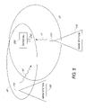
- FIG. 1 illustrates a telecommunication system in a single-cell configuration.
- FIG. 2 illustrates a block diagram of a telecommunication system according to one embodiment of the invention.
- FIG. 3 illustrates a detailed block diagram of the telecommunication system shown in FIG. 2 .
- FIG. 4 illustrates a block diagram of a telecommunication system according to another embodiment of the invention.
- FIG. 5 illustrates a telecommunication system in a multiple-cell configuration.
- FIG. 6 illustrates a flowchart that explains the operation of a telecommunication system according to one embodiment of the invention.
- FIG. 7 illustrates a flowchart that explains the operation of a telecommunication system according to another embodiment of the invention.
- FIG. 8 illustrates a block diagram of a transmitter model of the j-th base-station according to one embodiment of the invention.
- FIG. 9 illustrates a block diagram of a receiver model of the mobile station of interest according to one embodiment of the invention.
- FIG. 15 illustrates a chart showing block processing for exponential power delay profile according to one embodiment of the invention.
- FIG. 20 illustrates a block diagram of a data model and user-specific detection part of pilot-aided adaptive chip equalizer receiver according to one embodiment of the invention.
- FIG. 21 illustrates a block diagram of a pilot-aided updating part of pilot-aided chip equalizer receiver according to one embodiment of the invention.
- FIG. 22 illustrates a comparison chart of fractionally-spaced versus symbol-spaced adaptive chip equalizer receiver in quarter system load according to one embodiment of the invention.
- FIG. 23 illustrates a comparison chart of fractionally-spaced versus symbol-spaced adaptive chip equalizer receiver in half system load according to one embodiment of the invention.
- FIG. 24 illustrates a comparison chart of fractionally-spaced versus symbol-spaced adaptive chip equalizer receiver in full system load according to one embodiment of the invention.
- FIG. 25 illustrates a chart showing influence of Doppler-spread on performance of adaptive chip equalizer receiver according to one embodiment of the invention.
- FIG. 26 illustrates a flowchart that explains the operation of a telecommunication system according to another embodiment of the invention.
- FIG. 1 methods for communication, more in particular, wireless communication, between devices and the related devices are presented ( FIG. 1 ).
- at least data ( 10 ) is transmitted from at least one basestation ( 100 ) to at least one terminal ( 200 ).
- Said communication method is extendable to a case with a plurality of basestations ( FIG. 5 , 100 , 110 ), each basestation being designed for covering a single cell ( FIG. 5 , 20 , 21 ) around such basestation.
- a terminal receives typically signals from both the most nearby basestation and other basestations.
- the basestation has at least one antenna ( 110 ) and the terminal also has at least one physical antenna ( 210 ).
- the communication between the basestation(s) and the terminal is designed such that said communication is operable in a context with multiple terminals.
- substantially simultaneous communication between said basestation(s) and a plurality of terminals is happening, while still be able to distinguish at the terminal side which information was intended to be transmitted to a dedicated terminal.
- the notion of a user is introduced. It is assumed that with each terminal in such a multi terminal context at least one user is associated.
- the invented communication method and related devices exploit spreading with orthogonal codes as method for separating information streams being associated with different users. Hence at the basestation side information, more in particular data symbols, of different users, hence denoted user specific data symbols are available. After spreading spread user specific data symbols are obtained.
- the invented communication method blocks with a plurality of said chip symbols are transmitted.
- the transmitted signal thus comprises of a plurality of time overlapped coded signals, each coded signal being associated to an individual user and distinguishable only by a user specific encoding, based on the user signature or spreading codes.
- the distinguishing also exploits said basestation specific code.
- Such blocks have at least one pilot symbol (also called training sequence and denoted by s p [i] in equation (46)) being predetermined and known at both sides of the transmission link.
- a receiver FIG. 2 , 220
- Said receiver receives a spread-spectrum signal, corresponding to a superposition of the signals of all users active in the communication system or link, more in particular said superposition of signals is channel distorted.
- Said generation of at least two independent signals can be obtained by having either at least two antennas at the terminal, each independent signal being the signal ( 300 ) received at such antenna after the typical down-converting and filtering steps.
- polarization diversity [20] of said single antenna can be exploited or the temporal oversampling of the transmitted signal can be used.
- these independent signals are channel distorted versions (caused by the time-dispersive nature of the multi-path channel and described by equation (47)) of the signal transmitted by the basestation(s), including the transmitted block of chip symbols.
- the receiver or front-end circuitry provides for samples, typically complex baseband samples for a plurality of channels (either via different antennas or via polarisation diversity or oversampling) in digital format.
- the invention concerns a method for retrieving a desired user's symbol sequence (denoted by s k [i] in equation (46)), from a received signal transmitted in a communication context with multi-user interference.
- a step of inputting or receiving said received signal being a channel distorted version of a transmitted signal comprising a plurality of user data symbol sequences, each being encoded with a user specific known code is found.
- This multi-user interference suppression is obtained by performing combining of said independent signals resulting in a combined filtered signal ( 320 ).
- said combining also denoted chiplevel equalization, is a linear space-time combining.
- a combiner filter For said combining (chip-level equalizer) a combiner filter ( 230 ) is used.
- the (chip-level equalization) filter coefficients ( 420 ) of said combiner filter are determined directly from said independent signals ( 310 ), hence without determining an estimate of the channel characteristic.
- Said chip-level equalization filter is such that said transmitted signal is retrieved when applying said filter to said received signal.
- said filter coefficients are determined by using said independent signals and the knowledge of the pilot symbol.
- despreading and descrambling ( 240 ) with a code being the composite of said basestation specific scrambling code and one of said user specific codes (denoted by c k [n] in, equation (46)) is applied on said combined filtered signal ( 320 ) to obtain at least of one of said user specific data symbols.
- Said last step thus retrieves the desired user data symbol by correlating said retrieved transmitted signal ( 320 ) with the desired user specific known code and basestation specific code.
- despreading and descrambling step steps of performing correlations of modified received spread spectrum signals against selected replica of a spreading sequence are done, here with modified is meant linear space-time combining. Further said despreading step is used to extract the user corresponding to the spreading code used, more in particular the replica of the spreading code used at the transmitting side.
- said method for detection of a spread-spectrum signal can be formulated as comprising the steps of receiving a spread-spectrum signal including a training sequence, said signal corresponds to a superposition of signals of users; generating a first spread spectrum signal derived from said received spread spectrum signal and a second spread spectrum signal derived from said received spread spectrum signal; directly calculating the coefficients of a filter using knowledge of said training sequence from said derived spread-spectrum signals; and at least passing said first spread-spectrum signal and said second spread-spectrum signal different from said first spread-spectrum signal through said filter to generate a combined spread-spectrum signal; and despreading the filtered spread-spectrum signal, to extract a given user.
- said generated signals are independent, meaning received through another channel, either by having multiple antenna's, using the polarisation diversity of the available antennas or using temporal oversampling. Said generated signals are not a time-delayed version of each other.
- the combining of said generated signals is done in order to correct the signal for multi-user interference, more in particular to suppress multi-user interference.
- the combining filter is independent of the user one finally wants to detect.
- the combined signal is only then despread, meaning within the context of the description, correlated and decimated.
- the correlating is performed only with the user specific code of the user one wants to detect.
- the combining is done before correlating steps.
- the method of detection of a user signal thus comprises the steps of generating independent signals, filtering said generated independent signals with a filter being independent of said user, said filtering results in a combined signal; and despreading and descrambling with a code being user specific.
- the method of detection of a user signal involves in the detection part, only the code being user specific.
- the combining is done at chip-rate signals, hence before any step of despreading or even correlating is made.
- despreading is done as a first step before the filter is determined. However this despreading is done with the pilot code only.
- the method of filter determination despreads said generated independent signals with the pilot code while in the detection part despreading is performed on said filtered signal with the user specific code. It should be also understood that in some other embodiment in the part for determining the combining filter, thus not in the detection part itself, projecting rather than despreading is done as a first step before the filter is determined. However, this projecting is based on the multi-user code correlation matrix. Within the method ( FIG. 7 ) one can thus distinguish a filter determination part, denoted also initialisation, and a detection part using said filter. The method of filter determination projects said generated independent signals using a projection matrix derived from the multi-user code correlation matrix while in the detection part despreading is performed on said filtered signal with the user specific code.
- said performing of combining comprises the steps of performing filtering, preferable digital linear filtering ( 231 ) on said signals ( 310 ) to obtain the filtered signals ( 315 ) and combining ( 232 ), preferably linearly, said filtered signals to obtain said combined filtered signal ( 320 ).
- the filters used in said combining step have filter coefficients ( 420 ) being determined in a filter coefficient determination circuit ( 400 ) and are being determined by using said pilot symbol, more in particular by directly using said pilot symbol, hence the fact that said pilot symbol is known at the terminal side is exploited.
- said (filter) coefficients are determined without (explicit) channel estimation (the action of explicitly determining the coefficients of the Finite Impulse Response (FIR) channel filter that models the underlying multi-path propagation channel).
- said twostep combining ( 230 ) is used for suppressing multi-user interference, hence restoring the orthogonality of the codes.
- the chip-level equalization (filter coefficient) determination step does not rely on a-priori estimation of the channel characteristics. Also signal statistics are not used within the chiplevel equalization determination step, hence the notion of deterministic determination of said coefficients can be used.
- the direct filter coefficient determination is disclosed, indicating that said filter coefficients are determined such that one version or function of the combined filtered signal is as close as possible to a version or function of the pilot symbol.
- LS Least Squares
- RLS Recursive Least Squares
- Other minimization approaches such as Least Mean Squares (LMS) are also possible.
- a communication method is presented, denoted code division multiplexed pilot based determination, wherein for each user a user specific code is available but at least one of said user specific codes is used for spreading a known signal, denoted the pilot symbol.
- the associated user specific code is therefore denoted the pilot code.
- a so-called training-based approach is used, relying on the knowledge of said pilot symbol. More in particular said direct filter determination is such that the used version of the combined filtered signal is the combined filtered signal after despreading with a code being the composite code of said basestation specific scrambling code and said pilot code (denoted by c p [n] in equation (46) while said version of said pilot symbol is said pilot symbol itself. It should be noted however, that in practice said independent signals are first despread before combining takes place (see FIG. 6 ).
- said chip-level equalization filter is determined as a multiplication involving said known pilot symbol vector, a matrix involving the composite pilot codes, a Hankel structure output matrix, involving the received signals.
- a so-called semi-blind based approach is used, relying on the knowledge of said pilot symbol but also on characteristics of the codes.
- said direct filter determination is such that the used version of the combined filtered signal is the combined filtered signal after projecting on the orthogonal complement on the subspace spanned by the composite codes, being the codes composed of said base station specific scrambling code and said user specific codes, and said version of the pilot symbol is said pilot symbol spread with a composite code of said base station specific scrambling code and said pilot code.
- said independent signals are first projected before combining takes place (see FIG. 7 ).
- said chip-level equalization filter is determined as a multiplication involving said known pilot symbol vector, a matrix involving the pilot codes, a Hankel structure output matrix, involving the received signals and a matrix involving the user codes.
- a communication method is presented, denoted time division multiplexed pilot based method, wherein for each user a user specific code is available but in said block of symbols a plurality of a known pilot symbols are found, for each user code at least one.
- said transmitted block comprises at least two pilot symbols, each being spread by a user specific code.
- said pilot symbols can be denoted user specific known pilot symbols (represented by s k [i] in equation (64 )), each being encoded with a user specific known code.
- a so-called training-based approach is used, relying on the knowledge of said pilot symbol. More in particular said direct filter determination is such that the used version of the combined filtered signal is the combined filtered signal after despreading with a code being the composite code of said basestation specific scrambling code and a user specific code and said version of said pilot symbol is said pilot symbol itself. It should be noted however, that in practice said independent signals are first despread before combining takes place (see FIG. 6 ).
- said chip-level equalization filter is determined as a multiplication involving said known pilot symbol vector, a matrix involving the pilot codes and a Hankel structure output matrix.
- a so-called semi-blind based approach is used, relying on the knowledge of said pilot symbol but also on characteristics of the codes.
- said direct filter determination is such that the used version of the combined filtered signal is the pilot part of the combined filter signal; and said version of the pilot symbol is the sum of the spread pilot symbols within said transmitted block.
- said filter coefficients are determined such that the data part of the combined filter signal after projecting on the orthogonal complement on the subspace spanned by the composite codes, being the codes composed of said base station specific scrambling code and said user specific codes being as close as possible to the zero subspace. It should be noted however, that in practice said data part of said independent signals are first projected before combining takes place (see FIG. 7 ).
- said chip-level equalization filter is determined as a multiplication involving said known pilot symbol vector, a matrix involving the pilot codes, a Hankel structure output matrix, involving the received signals and a matrix involving the user codes.
- At least J base stations ( 100 , 110 ) are transmitting to said terminal having at least an integer number M at least J+1/(St*Sp) physical antenna's with St the temporal oversampling factor and Sp the polarisation diversity order. Note that alternatively less than M antenna's can be used by trading off complexity versus performance.
- steps of space-time combining ( 230 ) is performed J times as shown in FIG. 4 .
- Each of the resulting combined filtered signals ( 320 ) are multi-user interference suppressed versions of the signal transmitted from one of said basestations.
- despreading and descrambling ( 240 ) is performed J times as shown in FIG. 4 , to obtain J intermediate soft estimates ( 330 ) of a user specific data symbol.
- a step of combining ( 250 ), preferably linearly, of said J despread combined signals ( 330 ) to obtain a final soft estimate ( 340 ) of a user specific data symbol is performed followed by determining ( 260 ) from said final soft estimate a hard estimate ( 350 ) for said user specific data symbol.
- a wireless semi-blind communication method wherein besides user data symbols and pilot symbols, additional information is transmitted from the basestation(s) to said terminals.
- the space-time combiner filter has filter coefficients being determined by using said projection information.
- N a maximal amount of users, being N in case of time division multiplexed pilots and N ⁇ 1 in case of code division multiplexed pilots.
- an amount of active user Ua less than said maximal amount are active.
- said projection information is constructed by using or considering the active user's.
- said projection information is constructed by using or considering a predetermined set of assumed active user's, the size of said set being another upperbound on the amount of active users allowed.
- an apparatus with at least one antenna comprising (i) a receiver ( 220 ) capable of receiving a block ( 300 ) comprising of a plurality of chip symbols being data symbols spread by using scrambling and spreading codes and at least one pilot symbol, (ii) at least one linear space-time combining filter circuit ( 230 ), inputting at least two independent signals ( 310 ) derived from said received block and outputting a multi-user interference suppressed signal ( 320 ); (iii) a circuit ( 400 ) for determination of said combining filter circuit's coefficients ( 420 ), said filter circuit's coefficients being determined (directly) by using said pilot symbol; and (iv) at least one despreading circuit ( 240 ), used for despreading with one of said scrambling and spreading codes said multi-user interference suppressed signal ( 320 ).
- a radio receiver comprising a front-end circuitry ( 220 ) for providing complex baseband samples for a plurality of channels in digital format; an integrated adaptive digital combining circuitry ( 230 ), connected to said front-end circuitry, for combining said complex baseband samples; and a digital component ( 240 ), connected to said combining circuitry, being arranged to perform correlations of received spread spectrum signals against selected replica offsets of a spreading sequence.
- said apparatus for detecting of data signals from a transmitted signal in a Code-Division Multiple Access (CDMA) communication system, wherein the transmitted signal comprising a plurality of time overlapping coded signals, each coded signal associated to an individual user and distinguishable only by a user specific encoding (signature, spreading sequences), comprising a convolutional coder having at least two independent signals being representative for the transmitted signal as an input and outputting a single vector being representative for said transmitted signal; a decoder having said single vector as an input and outputting symbol information for at least one individual user.
- CDMA Code-Division Multiple Access
- an apparatus with at least one antenna comprising (i) a receiver ( 220 ) capable of receiving a block comprising of a plurality of chip symbols being data symbols spread by using scrambling and spreading codes, and projection information, enabling projecting of said independent signals on the orthogonal complement of the subspace spanned by scrambling and spreading codes; (ii) at least one linear space-time combining filter circuit ( 230 ), inputting at least two independent signals ( 310 ) derived from said received block and outputting a multi-user interference suppressed signal, (iii) a circuit ( 400 ) for determination of said combining filter circuit's coefficients with filter circuit's coefficients ( 420 ) being determined by using said projection information ( 430 ), and (iv) at least one despreading circuit ( 240 ), used for despreading with one of said scrambling and spreading codes said multi user interference suppressed signal ( 320 ).
- an apparatus comprising a plurality J of linear space-time combining filter circuits ( 230 ), each of said combining filter circuits inputting at least J+1 independent signals ( 310 ) and outputting a multi user interference suppressed signal ( 320 ), a circuit ( 400 ) for determination of said combining filters circuit's coefficients ( 420 ), a plurality of J despreading circuits ( 240 ), used for despreading said J multi-user interference suppressed signals ( 320 ); and a linear combining circuit ( 250 – 260 ) for combining said J spread multi-user interference suppressed signals.
- the last combining circuit can comprise of a substep of determining a soft estimate ( 250 ) and a substep of determining a hard estimate ( 260 ) based on said soft estimate.
- a radio receiver comprising a front-end circuitry ( 220 ) for providing complex baseband samples for a plurality of channels in digital format; a plurality of integrated adaptive digital combining circuitry ( 230 ), connected to said front-end circuitry, for combining said complex baseband samples; and a digital component ( 240 ), connected to said combining circuitry, being arranged to perform correlations of received spread spectrum signals against selected replica offsets of a spreading sequence.
- said apparatus for detection of a spread-spectrum signal can comprise of a processor arranged to provide a plurality of multiple input combining filter circuits ( 230 ), the plurality of multiple input combining filter circuits being respectively coupled to a plurality of despreading circuits ( 240 ).
- CDMA Code-Division Multiple Access
- the transmitted signal comprising a plurality of time overlapping coded signals, each coded signal associated to an individual user and distinguishable only by a user specific encoding (signature, spreading sequences), comprising a plurality of convolutional coders having at least two independent signals being representative for the transmitted signal as an input and outputting a single vector being representative for said transmitted signal; a decoder having said single vector as an input and outputting symbol information for at least one individual user.
- a user specific encoding signature, spreading sequences
- Said apparatus further comprises an algorithm unit ( 400 ), said algorithm unit is coupled to said plurality of combining filter circuits.
- said algorithm unit is an adaptive algorithm unit.
- the algorithm unit is used for calculating the coefficients of said combining filters based upon a training sequence within said spread-spectrum signal, more in particular exploiting a priori knowledge of the training sequence at the detection apparatus side of the communication link.
- the block transmitted from said at least one basestation to an at least one terminal comprises of a plurality of chip symbols scrambled with a base station specific scrambling code, said plurality of chip symbols comprising a plurality of spread user specific data symbols, being user specific data symbols spread by using user specific spreading codes and at least one pilot symbol.
- the transmitted signal can be a synchronous code division multiplex, employing user specific orthogonal Walsh-Hadamard spreading codes and a base-station specific aperiodic scrambling code.
- the user aperiodic code sequence is the multiplication of the corresponding spreading code and the base-station specific aperiodic scrambling code.
- the multi-user chip sequence (denoted by x[n] in equation (46)) comprises of K user signals plus at least one continuous pilot signal.
- the multi-user chip sequence (denoted by x[n] in equation (64)) comprises of a first set of user symbols, also denoted data symbols and a second set of known pilot symbols.
- the transmitted signal of each basestation can be a synchronous code division multiplex, employing user specific orthogonal Walsh-Hadamard spreading codes and a base-station specific aperiodic scrambling code.
- the user terminal then receives a sum of essentially all said transmitted signals.
- the user aperiodic code sequence is the multiplication of the corresponding spreading code and the base-station specific aperiodic scrambling code.
- the multi-user chip sequence comprises of K user signals plus at least one continuous pilot signal.
- the multi-user chip sequence comprises of a first set of user symbols, also denoted data symbols and a second set of known pilot symbols.
- G.1. a Multi-channel framework.
- Each base-station transmits a synchronous code division multiplex, employing short orthogonal Walsh-Hadamard spreading codes that are user specific and a long overlay scrambling code that is base-station specific.
- the multi-user chip sequence, transmitted by the j-th base-station x j [n] consists of K j active user signals and a continuous pilot signal:
- the data symbol sequence s k j [i] corresponds to the Dedicated Physical Data CHannel (DPDCH) for the k-th user from the j-th base-station whereas the pilot symbol sequence s p j [i] corresponds to the j-th base-station's Common PIlot CHannel (CPICH) in the UTRA specification for 3G systems [11].
- DPDCH Dedicated Physical Data CHannel
- CPICH Common PIlot CHannel
- the k-th user's composite code sequence for the j-th base-station c k j [n] is the multiplication of the user specific short Walsh-Hadamard spreading code ⁇ k j [n] (pilot-specific Walsh-Hadamard spreading code ⁇ p j [n]) and the base-station specific long scrambling code c s j [n].
- h m j (t) denote the continuous-time channel from the j-th base-station to the m-th receive antenna, including the transmit and receive filters.
- the received signal at the m-th receive antenna can then be written as:
- the channel matrix H has full column rank r.
- the input matrix X a has full row rank r.
- the pilot-aided block RAKE receiver the fully-trained, the pilot-trained and the enhanced pilot-trained block chip-level equalizer receiver.
- the receivers can detect the desired user's data symbols from each of the J active base-station signals. They address blocks of B symbols at once and, as shown in FIG. 9 , consist of J parallel branches, one for each base-station connected to the mobile station of interest. Each branch is made up of a linear space-time chip-level equalizer followed by a correlator.
- the space-time chip-level equalizer of the j-th branch linearly combines the discrete-time signals from the different antennas and tries to restore the multi-user chip sequence, transmitted by the j-th base-station.
- the chip-level equalizer receivers differ in the amount of a-priori information they assume to determine their equalizer coefficients.
- the correlator of the j-th branch descrambles and despreads the equalized signal with the desired user's composite code sequence for the j-th base-station.
- the final soft decisions about the desired user's data symbols are obtained by combining the correlator outputs of the different branches. These soft decisions are then input to a decision device that generates the final hard decisions.
- s K j j [s k j [0]s k j [1] . . . s k j [B ⁇ 1]]
- the 1 ⁇ B transmitted pilot symbol vector of the j-th base-station s p j is similarly defined as s k j .
- ⁇ k j [N ⁇ 1]] stacks the Walsh-Hadamard spreading code coefficients for the k-th user served by the j-th base-station and c s j [i] is simlarly defined as c k j [i].
- the pilot composite code matrix C p j , the pilot composite code vector c p j [i] and the pilot spreading code vector ⁇ p j of the j-th base-station are similarly defined as C k j , c k j [i] and ⁇ k j respectively.
- the A j (Q+1)M ⁇ A j BN super output matrix y i corresponding to the j-th base-station is then defined as follows:
- y i [ Y A 1 j ⁇ Y A 2 j ] .
- the pilot-aided channel estimation part of the j-th branch exploits the knowledge of the pilot composite code matrix and the pilot symbol vector to determine the j-th base-station's space-time channel coefficients [22].
- the columns of the (L j +1)M ⁇ B matrix V j contain the initial estimates of j-th base-station's spacetime channel vector at the different symbol instants.
- the (L j +1)M ⁇ BN output matrix Y ⁇ j is first despread with the j-th base-station's pilot composite code matrix C p j .
- the (L j +1)M ⁇ B despread output matrix Y ⁇ j C p j H is then component-wise multiplied with the complex conjugate of the (L j +1)M ⁇ B pilot symbol matrix S p j to remove the effect of the pilot symbol modulation.
- the final estimate of the j-th base-station's space-time channel vector is the average of the different initial estimates:
- G.2.c Fully-trained block chip-level equalizer receiver.
- the j-th branch of the fully-trained block chip-level equalizer receiver estimates the desired user's data symbol vector s k j j (we assume the desired user to be the k j -th user of the j-th base-station multiplex) from Y a j , with ⁇ j ⁇ Q ⁇ a j ⁇ j +L j , based on the knowledge of the j-th base-station's composite code matrix for the desired user C k j j and multi-user chip vector x 0 j .
- the fully-trained block chip-level equalizer receiver has zero spectral efficiency and is therefore useless in practice, its BER performance serves well as a lower bound on the BER probability of the proposed block chip equalizer receivers [14].
- w ⁇ aj j arg ⁇ ⁇ min w aj j ⁇ ⁇ w aj j ⁇ Y aj - x 0 j ⁇ 2 ( 19 ) which can be interpreted as follows.
- the equalized output matrix for the j-th base-station w a j j Y a j should be as close as possible to the known multi-user chip vector of the j-th base-station x 0 j in a Least Squares sense.
- the final soft symbol decisions for the desired user are then obtained by averaging the soft symbol decisions from each of the J branches:
- pilot-trained block chip-level equalizer receiver estimates the desired user's data symbol vector s k j j (we assume the desired user to be the k j -th user of the j-th base-station multiplex) from Y a j , with ⁇ j ⁇ Q ⁇ a j ⁇ j +L j , based on the knowledge of the j-th base-station's composite code matrix for the desired user C k j j , pilot composite code matrix C p j and pilot symbol vector s p j .
- g _ a j j arg ⁇ ⁇ ⁇ min g a j j ⁇ ⁇ g a j j ⁇ Y a j ⁇ C p j H - s p j ⁇ 2 ( 24 ) which can be interpreted as follows.
- the equalized output matrix for the j-th base-station g a j j Y a j is despread with the j-th base-station's pilot composite code matrix C p j .
- the equalized output matrix after despreading g a j j Y a j C p j H should then be as close as possible to the known pilot symbol vector of the j-th base-station s p j in a Least Squares sense.
- Equation 24 It is easy to prove that the LS problem in Equation 24 can be rewritten as follows:
- g _ aj j arg ⁇ ⁇ min g aj j ⁇ ⁇ g aj j ⁇ Y aj ⁇ ( C p j H ⁇ C p j ) - s p j ⁇ C p j ⁇ 2 ( 25 ) showing that the equalized output matrix g a j j Y a j is first projected on the subspace spanned by the j-th base-station's pilot composite code matrix C p j .
- the equalized output matrix after projecting g a j j Y a j (C p j H C p j ) should then be as close as possible to the known pilot chip vector of the j-th base-station s p j C p j in a Least Squares sense.
- Equations 20 and 75 remain valid if we replace w a j j by g a j j .
- G.2.e Enhanced pilot-trained block chip-level equalizer receiver The j-th branch of the enhanced pilot-trained block chip-level equalizer receiver estimates the desired user's data symbol vector s k j j from Y a j , with ⁇ j ⁇ Q ⁇ a j ⁇ j +L j , based on the knowledge of the j-th base-station's multi-user composite code matrix C d j , pilot composite code matrix C p j and pilot symbol vector s p j .
- f _ a j j , s _ d j arg ⁇ ⁇ ⁇ min f a j j , s d j ⁇ ⁇ f a j j ⁇ Y a j - s d j ⁇ C d j - s p j ⁇ C p j ⁇ 2 ( 28 ) Since the LS cost function is a quadratic form in f a j j ,s d j , the minimisation can be done independently for f a j j and s d j .
- f _ aj j arg ⁇ ⁇ min f aj j ⁇ ⁇ f aj j ⁇ Y aj ⁇ ( I BN - C d j H ⁇ C d j ) - s p j ⁇ C p j ⁇ 2 ( 30 ) which can be interpreted as follows.
- the equalized output matrix for the j-th base-station f a j j Y a j is projected on the orthogonal complement of the subspace spanned by the j-th base-station's multi-user composite code matrix C d j .
- the equalized output matrix after projecting f a j j Y a j (I BN ⁇ C d j H C d j ) should then be as close as possible to the known pilot chip vector of the j-th base-station s p j C p j in a Least Squares sense.
- K j N ⁇ 1
- Equation 30 It is easy to prove that the modified LS problem of Equation 30 can be rewritten as follows:
- f _ aj j ⁇ arg ⁇ ⁇ min f aj j ⁇ ⁇ ⁇ f aj j ⁇ Y aj ⁇ C p j H - s p j ⁇ 2 + ⁇ ⁇ f aj j ⁇ Y aj ⁇ ( I BN - C d j H ⁇ C d j - C p j H ⁇ C p j ) ⁇ 2 ⁇ ( 31 ) showing that the enhanced pilot-trained LS problem naturally decouples into two different parts: a training-based part and a fully-blind part.
- the training-based part corresponds to the pilot-trained chip equalizer of Equation 24.
- the fully-blind part projects the equalized output matrix f a j j Y a j on the orthogonal complement of the subspace spanned by both the j-th base-station's multi-user composite code matrix C d j and the j-th base-station's pilot composite code matrix C p j .
- the energy in the equalized output matrix after projecting f a j j Y a j (I BN ⁇ C d j H C d j ⁇ C p j H C p j ) should be as small as possible in a Least Squares sense which actually corresponds to the Minimum Output Energy (MOE) criterion of [18] and [19].
- MOE Minimum Output Energy
- Equations 20 and 75 remain valid if we replace w a j j by f a j j .
- the block version of the different chip equalizer receivers addresses a block of B symbols at once and is only suited for a block fading channel, that remains constant during the entire duration of the block. Since in practice, the multi-path fading channel is time-varying, we have to devise an adaptive version as well that updates the equalizer coefficients on the fly. In this section, we derive an adaptive version of the different chip-level equalizer receivers from their corresponding block version and provide complexity figures for each of them.
- the adaptive receivers address a single symbol at once and consist of J parallel branches, one for each base-station connected to the mobile station of interest.
- the j-th branch basically consists of two parts: a pilot-aided updating part and a user specific detection part.
- Y a ⁇ [ i ] [ y ⁇ [ i ⁇ ⁇ N + a ] ⁇ y ⁇ [ ( i + 1 ) ⁇ N + a - 1 ] ⁇ ⁇ ⁇ y ⁇ [ iN + a + Q ] ⁇ y ⁇ [ ( i + 1 ) ⁇ N + a + Q - 1 ] ] ( 32 ) where i represents the symbol instant and a the processing delay.
- the K j ⁇ N multi-user spreading code matrix ⁇ d j can be similarly defined as C d j [i], stacking the j-th base-station's active user spreading code vectors for each symbol instant.
- the pilot-aided channel updating part of the j-th branch exploits the knowledge of the pilot composite code vectors and pilot symbols of the corresponding j-th base-station [22]. It continuously updates the j-th base-station's space-time channel vector at the symbol rate. By having a closer look at the corresponding block processing algorithm in Equation 13, it is rather straightforward to derive an adaptive processing algorithm for the j-th branch.
- the correction term is the component-wise multiplication of the new despread output matrix block Y ⁇ j [i]c p j [i] H and the complex conjugate of the new pilot symbol vector s p j [i].
- the pilot-aided channel updating part for the j-th branch consists of three computational steps per time update, namely first a pilot despreading step, then a pilot symbol modulation removal step and finally an updating step.
- the pilot despreading step requires O(L j MN) computations.
- the pilot symbol modulation removal step as well as the updating step require O(L j M) computations. So, the pilot-aided channel updating part requires
- the user-specific detection part consists of two computational steps per time update, namely first a coherent combining step and then a correlation step.
- the coherent combining step requires O(NL j M) computations.
- the correlation step requires O(N) computations. So, the user-specific detection part requires
- the final soft decision s du [i] about the desired user's i-th symbol is then obtained with O(J) complexity by averaging the soft decisions of the different branches:
- G.3.c Fully-trained adaptive chip-level equalizer receiver.
- the j-th branch of the fully-trained adaptive chip-level equalizer receiver estimates the desired user's data symbol s k j j [i] (we assume the desired user to be the k j -th user of the j-th base-station multiplex) from the set Y a j [ 0 ], Y a j [ 1 ], . . .
- the fully-trained updating part of the j-th branch exploits the knowledge of the multi-user chip vectors of the corresponding j-th base-station. It continously updates the equalizer coefficients at the symbol rate using a Square Root Information (SRI) RLS type of adaptive algorithm [24].
- SRI Square Root Information
- T a j j [i] represents the orthogonal updating matrix at the i-th symbol instant that can be written as a sequence of Givens transformations [24].
- the fully-trained QRD-updating step tracks a (Q+1)M ⁇ (Q+1)M lower-triangular factor R a j j [i] and a corresponding 1 ⁇ (Q+1)M right-hand side z a j j [i].
- the fully-trained SRI-RLS updating part for the j-th branch consists of two computational steps per time update, namely first a triangular QRD-updating step and then a triangular backsubstitution step.
- the QRD-updating step amounts to triangularizing a structured matrix, namely a triangular matrix plus N extra columns, and requires O(NQ 2 M 2 ) computations.
- the triangular backsubstitution step requires O(Q 2 M 2 ) computations. So, the fully-trained updating part requires O(JNQ 2 M 2 ) computations in total for all J branches.
- the user-specific detection part also consists of two computational steps per time update, namely first an equalization step and then a correlation step.
- the equalization step requires O(NQM) computations.
- the correlation step requires O(N) computations. So, the user-specific detection part requires O(JNQM) computations in total for all J branches.
- the final soft decision s du [i] about the desired user's i-th symbol is then obtained with O(J) complexity by averaging the soft decisions of the different branches:
- pilot-trained adaptive chip-level equalizer receiver estimates the desired user's data symbol s k j j [i] (we assume the desired user to be the k j -th user of the j-th base-station multiplex) from the set Y a j [ 0 ], Y a j [ 1 ], . . .
- the pilot-trained updating part of the j-th branch exploits the knowledge of the pilot composite code vectors and pilot symbols of the corresponding j-th base-station [25]. It continously updates the equalizer coefficients at the symbol rate using a Square Root Information (SRI) RLS type of adaptive algorithm [24].
- SRI Square Root Information
- the new incoming output matrix block Y a j [i] is first despread with the j-th base-station's pilot composite code vector for the i-th symbol instant c p j [i].
- the new despread output matrix block Y a j [i]c p j [i] H is then used together with the new pilot symbol s p j [i] in a QRD-updating step:
- the pilot-trained QRD-updating step tracks a (Q+1)M ⁇ (Q+1)M lower-triangular factor R a j j [i] and a corresponding 1 ⁇ (Q+1)M right-hand side z a j j [i].
- the pilot-trained SRI-RLS updating part for the j-th branch consists of three computational steps per time update, namely first a pilot despreading step, then a triangular QRD-updating step and finally a triangular backsubstitution step.
- the pilot despreading step requires O(QMN) computations.
- the QRD-updating step amounts to triangularizing a structured matrix, namely a triangular matrix with one extra column, and requires O(Q 2 M 2 ) computations.
- the triangular backsubstitution step also requires O(Q 2 M 2 ) computations. So, the pilot-trained updating part requires O(JQMN+JQ 2 M 2 ) computations in total for all J branches.
- Equations 38 and 39 remain valid if we replace w a j j [i] by g a j j [i].
- G.3.e Enhanced pilot-trained adaptive chip-level equalizer receiver The j-th branch of the enhanced pilot-trained adaptive chip-level equalizer receiver estimates the desired user's data symbol s k j j [i] (we assume the desired user to be the k j -th user of the j-th base-station multiplex) from the set Y a j [ 0 ], Y a j [ 1 ], . . .
- the enhanced pilot-trained updating part of the j-th branch exploits the knowledge of all composite code vectors (so both pilot and user composite code vectors) and pilot symbols of the corresponding j-th base-station. It continously updates the equalizer coefficients at the symbol rate using a Square Root Information (SRI) RLS type of adaptive algorithm [24].
- SRI Square Root Information
- the new projected output matrix block Y a j [i]P d j [i] is then used together with the new pilot chip vector s p j[i]c p j [i] in a QRD-updating step:
- the enhanced pilot-trained QRD-updating step tracks a (Q+1)M ⁇ (Q+1)M lower-triangular factor R a j j [i] and a corresponding 1 ⁇ (Q+1)M right-hand side z a j j [i].
- the enhanced pilot-trained SRI-RLS updating part for the j-th branch consists of four computational steps per time update, namely first a projection step, then a pilot symbol spreading step, next a triangular QRD-updating step and finally a triangular backsubstitution step.
- the projection step decomposes into two substeps, namely the projection matrix calculation substep and the projection matrix multiplication substep.
- the projection matrix calculation substep would normally require O(K j N 2 ) computations.
- the multi-user spreading code correlation matrix does not depend on the symbol instant i, it can be precalculated at the base-station and broadcasted to all active mobile stations. This leaves only O(N 2 ) complexity for the projection matrix calculation substep at the mobile station.
- the projection matrix multiplication substep requires O(QMN 2 ) computations.
- the pilot symbol spreading step only requires O(N) computations.
- the QRD-updating step amounts to triangularizing a structured matrix, namely a triangular matrix plus N extra columns, and requires O(NQ 2 M 2 ) computations.
- the triangular backsubstitution step requires O(Q 2 M 2 ) computations. So, the enhanced pilot-trained updating part requires O(JQMN 2 +JNQ 2 M 2 ) computations in total for all J branches.
- Equations 38 and 39 remain valid if we replace w a j j [i] by f a j j [i].
- Table I compares the complexity of the different adaptive chip-level equalizer receivers.
- the user-specific detection part is common to all receivers.
- all receivers have linear complexity in the number of actively tracked base-stations J.
- the updating part of the pilot-aided adaptive RAKE receiver (PA-RAKE) has linear complexity in both the total number of RAKE fingers LM and the spreading factor N.
- the updating part of all other receivers has quadratic complexity in the total number of equalizer coefficients QM.
- the updating part of both the fully-trained (FT-CE) and the pilot-trained (PT-CE) adaptive chip-level equalizer receiver has linear complexity whereas that of the enhanced pilot-trained (EPT-CE) adaptive chip-level equalizer receiver has quadratic complexity in the spreading factor N.
- the updating part of the EPT-CE is N times more complex than that of the PT-CE. Note that the complexity figure of the EPT-CE agrees with the complexity figure of the LS channel estimators for long code DS-CDMA systems recently proposed in [26].
- both the EPT-CE and the FT-GE outperform the PA-RAKE for low to high SNR per bit.
- the PT-CE only outperforms the PA-RAKE at rather high SNR per bit.
- the FT-CE approaches the SUB rather closely.
- the EPT-CE and the PA-RAKE have similar performance. Only at medium to high SNR per bit
- the EPT-CE outperforms the PA-RAKE.
- the PT-CE has worse performance than the PA-RAKE. Only at rather high SNR per bit
- the PT-CE has better performance than the PA-RAKE.
- the PA-RAKE exhibits an error floor at a BER of 2 ⁇ 10 ⁇ 1 .
- the curves for the PT-CE, the EPT-CE and the FT-CE shift up due to the increased MUI but remain near/far resistant.
- the PT-CE and the EPT-CE have exactly the same performance (as discussed in Subsection G.2.e) but still outperform the PA-RAKE receiver, that exhibits an error floor at a BER of 5 ⁇ 10 ⁇ 2 .
- the PT-CE and the EPT-CE exhibit a 3.3 dB loss at a BER of 10 ⁇ 3 .
- G.4.b Adaptive processing.
- FIGS. 16 and 17 compare the performance of the pilot-aided adaptive RAKE receiver (PA-RAKE) with weighting factor
- ⁇ 1 2 , the pilot-trained (PT-CE), the enhanced pilot-trained (EPT-CE) and the fully-trained (FT-CE) adaptive chip-level equalizer receiver for half respectively full system load.
- the EPT-CE outperforms the PT-CE by 2.9 dB and suffers a 1.9 dB loss compared to the FT-CE at a BER of 10 ⁇ 3 .
- the PA-RAKE exhibits an error floor at a BER of 10 ⁇ 2 .
- the PT-CE and the EPT-CE have exactly the same performance and suffer a 5 dB loss compared to the FT-CE at a BER of 10 ⁇ 1 .
- the PA-RAKE exhibits an error floor at a BER of 4 ⁇ 10 ⁇ 2 .
- the pilot-trained and the enhanced pilot-trained receiver have exactly the same performance.
- the enhanced pilot-trained receiver outperforms the pilot-trained receiver and its performance comes close to that of the ideal fully-trained receiver.
- the enhanced pilot-trained chip-level equalizer can be viewed as a semi-blind chip equalizer, since its cost function can be written as the sum of a training-based term and a fully-blind term.
- the Least Squares block processing algorithms on the one hand, detect blocks of B symbols at once. For large block lengths B ⁇ , the performance of both the pilot-trained and the enhanced pilot-trained block chip equalizer receiver converges to the performance of the fully-trained block chip equalizer receiver. Conversely, the performance gain of the enhanced pilot-trained block chip-level equalizer receiver compared to the pilot-trained block chip-level equalizer receiver increases for decreasing block lengths B. Both receivers can deal with a severe near/far situation caused by the power control in the downlink. Moreover they are robust against both channel order over- and underestimation and they can cope with channels with a head or tail approaching zero.
- Both the pilot-trained and the enhanced pilot-trained adaptive chip-level equalizer receiver can track time-varying multi-path channels.
- the pilot-trained adaptive chip-level equalizer receiver outperforms the pilot-aided adaptive RAKE receiver at medium to high SNR per bit while the enhanced pilot-trained adaptive chip-level equalizer receiver always outperforms the pilot-aided adaptive RAKE receiver.
- Both the pilot-trained and the enhanced pilot-trained chip-level equalizer receiver have linear complexity in the number of tracked base-stations J and quadratic complexity in the total number of equalizer coefficients QMS t S p .
- the enhanced pilot-trained receiver has quadratic complexity in the spreading factor N.
- the enhanced pilot-trained adaptive chip-level equalizer receiver exhibits a N times higher complexity than the regular pilot-trained adaptive chip-level equalizer receiver.
- the enhanced pilot-trained spacetime chip-level equalizer receiver is a promising receiver for future WCDMA terminals, from a performance as wel as a complexity point of view.
- H.1. a Multi-channel framework. Let us consider the forward link of a single-cell WCDMA system with K active user terminals.
- the base-station transmits a synchronous code division multiplex, employing user specific orthogonal Walsh-Hadamard spreading codes and a base-station specific a periodic scrambling code.
- the transmitted multi-user chip sequence consists of K user signals and a continuous pilot signal:
- Each user's data symbol sequence s k [i] (pilot symbol sequence s p [i]) is spread by a factor N with the user code sequence c k [n] (pilot code sequence c p [n]).
- the k-th user aperiodic code sequence c k [n] (pilot code sequence c p [n]) is the concatenation of the corresponding Walsh-Hadamard spreading code and the base-station specific a periodic scrambling code.
- h m (t) denote the continuous-time channel from the base-station to the m-th receive antenna, including the transmit and receive filters.
- e[n] is similarly defined as y[n]
- h m ⁇ [ n ] h m ⁇ ( n ⁇ N T ) is the discrete-time channel impulse response from the base-station to the m-th receive antenna. Note that we model h[n] as an M ⁇ 1 FIR vector filter of order L.
- H.2.a Block processing The block processing algorithm for the semi-blind chip equalizer detects B data symbols at once.
- the KB ⁇ BN user code sequence matrix C d stacks the code sequence matrices of the individual users:
- C d [C 1 T . . . C K T ] T
- C k is the k-th user's B ⁇ BN code sequence matrix:
- the B ⁇ BN pilot code sequence matrix C p and the pilot code sequence vector c p [i] are similarly defined as C k respectively c k [i].
- the semi-blind block processing problem addressed here is to compute the desired user's data symbol sequence s 1 (we assume the first user to be the user of interest) from Y a , with ⁇ Q ⁇ a ⁇ L, based on the knowledge of the user code sequence matrix C d , the pilot code sequence matrix C p and the pilot symbol vector s p .
- s 1 we assume the first user to be the user of interest
- the channel matrix H has full column rank r.
- the input matrix X a has full row rank r.
- the second assumption requires that: BN ⁇ r
- f _ a , s _ d arg ⁇ ⁇ ⁇ min f a , s d ⁇ ⁇ f a ⁇ Y a - s d ⁇ C d - s p ⁇ C p ⁇ 2 ( 53 ) Since the LS cost function is a quadratic form in f a , s d , the minimisation can be done independently for f a and s d . In order to obtain a direct semi-blind equalizer estimation, we first solve for s d , assuming f a to be known and fixed.
- f _ a arg ⁇ ⁇ min f a ⁇ ⁇ f a ⁇ Y a ⁇ ( I BN - C d H ⁇ C d ) - s p ⁇ C p ⁇ 2 ( 55 ) which can be interpreted as follows.
- the equalized signal f a Y a is projected on the orthogonal complement of the space spanned by the user code sequences. Furthermore, the projected equalized signal f a Y a (I BN ⁇ C d H C d ) should be as close as possible to the transmitted pilot chip sequence s p C p in a Least Squares sense.
- f a s p C p Y a H ⁇ Y a ( I BN ⁇ C d H C d ) Y a H ⁇ ⁇ 1 (56)
- the block processing algorithm for the training-based chip equalizer that detects B data symbols at once, can again be formulated as a LS minimisation problem:
- g _ a arg ⁇ ⁇ min g a ⁇ ⁇ g a ⁇ Y a ⁇ C p H - s p ⁇ 2 ( 59 ) which can be interpreted as follows.
- the equalized signal g a Y a is despread with the pilot code sequence matrix C p .
- the equalized signal after despreading g a Y a C p H should then be as close
- the QRD-updating step tracks a lower-triangular factor ⁇ circumflex over (R) ⁇ a [i] and a corresponding right-hand side ⁇ circumflex over (z) ⁇ a [i].
- I.1. a Multi-channel framework. Let us consider the forward link of a single-cell WCDMA system with K active user terminals.
- the base-station transmits a synchronous code division multiplex, employing user specific orthogonal Walsh-Hadamard spreading codes and a base-station specific a periodic scrambling code.
- the transmitted multi-user chip sequence can then be written as:
- the pilot symbols correspond to the Dedicated Physical Control CHannel (DPCCH) whereas the data symbols correspond to the Dedicated Physical Data CHannel (DPDCH) in the UTRA specification for 3G mobile communications [11].
- DPCCH Dedicated Physical Control CHannel
- DPDCH Dedicated Physical Data CHannel
- Each user's symbol sequence s k [i] is spread by a factor N with the length- ⁇ N user code sequence c k [n].
- the k-th user aperiodic code sequence is the multiplication of the user specific Walsh-Hadamard spreading code and the base-station specific aperiodic scrambling code.
- the user terminal is equipped with M receive antennas.
- the received antenna signals are sampled at the chiprate
- e[n] is the M ⁇ 1 received noise vector sequence
- h[n] [h 1 [n] h 2 [n] . . . h M [n]]
- T is the M ⁇ 1 discrete-time vector channel from the base-station to the M receive antennas. Note that we model h[n] as an M ⁇ 1 FIR vector filter of order L.
- Y a [ y ⁇ [ a ] ⁇ y ⁇ [ a + BN - 1 ] ⁇ ⁇ y ⁇ [ a + Q ] ⁇ y ⁇ [ a + Q + BN - 1 ] ]
- B the block length
- a the processing delay
- Q+1 the temporal smoothing factor.
- ZF Zero-Forcing
- the channel matrix H has full column rank r.
- the input matrix X a has full row rank r.
- the second assumption requires that: BN ⁇ r (69) which states that the number of observed chip samples BN should be larger than the system order r.
- Both chip equalizer receivers consist of a linear space-time chip equalizer followed by a correlator.
- the space-time chip equalizer tries to restore the transmitted multi-user chip sequence by linearly combining the discrete-time signals from the different receive antennas.
- the correlator descrambles and despreads the equalized signal with the desired user's aperiodic code sequence and generates the soft decisions about the desired user's data symbols. These soft decisions are then input to a decision device that generates the final hard decisions.
- the DPCCH-trained and the enhanced DPCCH-trained chip equalizer receivers differ in the amount of a-priori information they assume to determine their equalizer coefficients.
- LS Least Squares
- x 0 s p C p +s d C d (70)
- s p is the 1 ⁇ KP total pilot symbol vector that stacks the pilot symbol vectors of the different active users:
- s p [s p,1 . . .
- s p,K [s k [0] s k [1] . . . s k [P ⁇ 1]]
- the 1 ⁇ KD total data symbol vector s d and the 1 ⁇ D data symbol vector of the k-th user s d,k are similarly defined as s p respectively s p,k .
- C _ p , k [ c k ⁇ [ 0 ] ⁇ c k ⁇ [ P - 1 ] ]
- the KD ⁇ BN total data code sequence matrix C d and the D ⁇ BN data code sequence matrix of the k-th user C d,k are similarly defined as C p respectively C p,k .
- the D ⁇ DN effective data code sequence matrix of the k-th user C d,k and the KD ⁇ DN total effective data code sequence matrix C d are similarly defined as C p,k respectively C p .
- the DPCCH-trained block chip equalizer receiver estimates the desired user's data symbol vector s d,k (we assume the desired user to be the k-th user of the base-station multiplex) from Y a , with ⁇ Q ⁇ a ⁇ L, based on the knowledge of the desired user's data code sequence matrix C d,k , the desired user's pilot code sequence matrix C p,k and the desired user's pilot symbol vector s p,k .
- g _ a arg ⁇ ⁇ min g a ⁇ ⁇ g a ⁇ Y a ⁇ C p , k H - s p , k ⁇ 2 ( 72 ) which can be interpreted as follows.
- the equalized signal g a Y a is first despread with the desired user's pilot code sequence matrix C p,k .
- the equalized signal after despreading g a Y a C p,k H should then be as close as possible to the desired user's known pilot symbol vector s p,k in a Least Squares sense.
- Equation 72 It is easy to prove that the LS problem in Equation 72 can be rewritten as follows:
- g _ a arg ⁇ ⁇ ⁇ min g a ⁇ ⁇ ⁇ g a ⁇ Y p , a ⁇ C _ p , k H - s p , k ⁇ 2 ( 73 ) showing that the DPCCH-trained LS problem only exploits the pilot part Y p,a of the output matrix Y a .
- the soft decisions s d,k are fed into a decision device that determines the nearest constellation point. This results in the hard decisions ⁇ d,k .
- the enhanced DPCCIH-trained block chip equalizer receiver estimates the desired user's data symbol vector s d,k from Y a , with ⁇ Q ⁇ a ⁇ L, based on the knowledge of the total data code sequence matrix C d , the total pilot code sequence matrix C p and the total pilot symbol vector s p .
- f _ a , s _ d arg ⁇ ⁇ min f a , s d ⁇ ⁇ f a ⁇ Y a - s d ⁇ C d - s p ⁇ C p ⁇ 2 ( 77 ) Since the LS cost function is a quadratic form in f a ,s d , the minimisation can be done independently for f a and s d . In order to obtain a direct equalizer estimation, we first solve for s d , assuming f a to be known and fixed.
- f _ a arg ⁇ ⁇ min f a ⁇ ⁇ ⁇ f a ⁇ Y a ⁇ ( I BN - C d H ⁇ C d ) - s p ⁇ C p ⁇ 2 ( 79 ) which can be interpreted as follows.
- the equalized signal f a Y a is projected on the orthogonal complement of the subspace spanned by the total data code sequence matrix C d .
- the equalized signal after projecting f a Y a (I BN ⁇ C d H C d ) should then be as close as possible to the known total pilot chip sequence vector s p C p in a Least Squares sense.
- Equation 80 It is easy to prove that the modified LS problem of Equation 79 can be rewritten as in Equation 80 (see the top of the next page) showing that the enhanced DPCCH-trained LS problem naturally decouples into two different parts: a fully-trained part and a fully-blind part.
- the fully-trained part (corresponding to the first term in Equation 80)
- f _ a arg ⁇ ⁇ min f a ⁇ ⁇ ⁇ ⁇ f a ⁇ Y p , a - s p ⁇ C _ p ⁇ 2 + ⁇ f a ⁇ Y d , a ⁇ ( I DN - C _ d H ⁇ C _ d ) ⁇ 2 ⁇ ( 80 ) forces the equalized signal to be as close aspossible (in a Least Squares sense) to the transmitted multi-user chip sequence during the training mode of the receiver.
- the fully-blind part projects the equalized signal on the orthogonal complement of the subspace spanned by the total effective data code sequence matrix during the blind mode of the receiver.
- the energy in the projected equalized signal should be as small as possible (in a Least Squares sense) which actually corresponds to a Minimum Output Energy (MOE) criterion.
- MOE Minimum Output Energy
- the LS solution for f a can be written as: f a 32 s p C p Y a H ⁇ Y a ( I BN ⁇ C d H C d ) Y a H ⁇ ⁇ 1 (81)
- the obtained LS enhanced DPCCH-trained chip equalizer f a may subsequently be used to extract the 1 ⁇ D desired user's vector of soft symbol decisions s d,k . Equation 75 remains valid if we replace g a by f a .
- the DPCCH-trained updating part can work in two modes: a training mode and a decision-directed mode.
- a training mode By having a closer look at the corresponding LS block processing algorithm in Equation 73, it is rather straightforward to derive an SRI-RLS type of adaptive processing algorithm.
- the (Q+1)M ⁇ N new incoming output matrix block Y a [i] is first despread with the desired user's code sequence vector for the i-th symbol instant c k [i].
- the new despread output matrix block Y a [i]c k H [i] is then used together with the new desired user's pilot symbol s k [i] (during the training mode) or the new desired user's estimated data symbol ⁇ k [i] (during the decision-directed mode) in a QRD-updating step [24].
- the QRD-updating step tracks a (Q+1)M ⁇ (Q+1)M lower triangular factor R a [i] and a corresponding 1 ⁇ (Q+1)M right-hand side z a [i].
- I.3.b Enhanced DPCCH-trained adaptive chip equalizer receiver.
- the enhanced DPCCH-trained updating part can also work in two modes: a training mode and a blind mode. By having a closer look at the corresponding LS block processing algorithm in Equation 80, it is rather straightforward to derive an SRI-RLS type of adaptive processing algorithm.
- the training mode the new incoming output matrix block Y a [i] is used together with the 1 ⁇ N new multi-user chip sequence vector x 0 [i] in a QRD-updating step.
- the new incoming output matrix block Y a [i] is first projected on the orthogonal complement of the subspace spanned by the active user codes, using the N ⁇ N projection matrix I N ⁇ C d H [i]C d [i].
- the new projected output matrix block is then used together with the 1 ⁇ N zero vector 0 1 ⁇ N in a QRD-updating step [24].
- DPCCH-T CE DPCCH-trained
- E-DPCCH-T CE enhanced DPCCH-trained chip equalizer
- the ideal RAKE receiver dearly exhibits an error floor due to the MUI while both the DPCCH-T and the F-DPCCH-T CE receiver are near/far resistant.
- the E-DPCCH-T CE receiver realizes a 5 dB gain at a BER of 10 ⁇ 2 compared to the regular DPCCH-T CE receiver. Moreover, its performance nearly approaches that of the ideal F-T CE receiver.
- the LS block chip equalizer receivers on the one hand that detect B symbols at once, are suited for packet-switched type of communication.
- the performance gain of the enhanced DPCCH-trained receiver compared to the regular DPCCH-trained receiver increases for decreasing pilot length P.
- the RLS adaptive chip equalizer receivers on the other hand, that detect symbol by symbol, are suited for circuit-switched type of communication. They are able to track time-varying multipath channels and outperform the conventional RAKE receiver with perfect channel knowledge.
- the enhanced DPCCH-trained chip equalizer receiver is a promising receiver for future WCDMA terminals, from a performance as well as complexity point of view.
- the base-station transmits a synchronous code division multiplex, employing user-specific orthogonal Walsh-Hadamard spreading codes and a site-specific aperiodic scrambling code.
- the transmitted multi-user chip sequence during the i-th symbol period consists of K user signals and a continuous pilot signal
- the total transmitted multi-user chip sequence is then the sum of different time-shifted versions of x[i,n]:
- the impulse response of the time-varying composite channel during the i-th symbol period consisting of the low-pass transmit and receive filters and the actual propagation channel, can be modeled as follows:
- h (i) [m] and ⁇ m are the time-varying complex channel gain respectively the delay of the m-th path.
- the composite chip waveform ⁇ RC (t) includes both transmit and receive low-pass filters and has a raised-cosine spectrum.
- the total received baseband signal at the mobile user terminal can be written as:
- y ⁇ ( t ) ⁇ i ⁇ ⁇ n ⁇ x ⁇ [ i , n ] ⁇ ⁇ h ( i ) ⁇ ( t - ( Ni + n ) ⁇ T c ) + ⁇ ⁇ ( t ) ( 86 )
- H q [ ⁇ i ] [ ⁇ h q ⁇ [ i , L ] h q ⁇ [ i , L - 1 ] ⁇ h q ⁇ [ i , 0 ] 0 ⁇ 0 0 h q ⁇ [ i , L ] ⁇ h q ⁇ [ i , 1 ] h q ⁇ [ i , 0 ] ⁇ 0 ⁇ ⁇ ⁇ ⁇ ⁇ ⁇ 0 0 h q ⁇ [ i , L ] ⁇ h q ⁇ [ i , 1 ] h q ⁇ [ i , 0 ] ] ( 89 )
- ⁇ (t) is a zero-mean complex colored Gaussian noise process with power spectral density ⁇ 2 .
- the noise coloring is due to the receive low-pass filter.
- the signal y(t) is now temporally oversampled at twice
- H ⁇ [ i ] [ H 1 ⁇ [ i ] H 2 ⁇ [ i ] ] ( 88 ) while ⁇ [i] is the received noise vector during the i-th symbol period.
- the (3K+3)-dimensional bit vector b[i] contains the user and pilot transmitted bits during the i-th symbol period as well as the previous and the next symbol period.
- the (N+2F+L) ⁇ (3K+3) code matrix C[i] contains the aperiodic spreading codes corresponding to each of the transmitted bits while the (3K+3)-dimensional diagonal matrix A contains the amplitudes of the user signals and the pilot signal.
- the proposed pilot-aided adaptive chip equalizer receiver is well-suited for implementation in a mobile user terminal, operating in fast fading multipath channels. By exploiting the presence of a continuous pilot signal in forthcoming third generation cellular and LEO satellite communication systems, it continuously updates at the symbol rate using a simple NLMS or a more advanced RLS adaptive scheme.
- the proposed receiver basically consists of two parts: a user-specific detection part and a pilot-aided updating part.
- the user-specific detection part operates like the conventional chip equalizer receiver, as shown in FIG. 20 . Initially, it uses for each symbol instant the corresponding equalizer coefficients, drawn from the pilot-aided updating part (see next subsection), to equalize the received signal. Finally, it descrambles and despreads the equalized signal with the aperiodic spreading code of the user of interest (user k) and makes a decision about the transmitted data symbol.
- the total equalizer coefficient vector g H [i] [g 1 H [i] g 2 H [i]] stacks the equalizer coefficient vectors for the first and the second phase.
- G q ⁇ [ i ] [ g q ⁇ [ i , - F ] g q ⁇ [ i , - F + 1 ] ⁇ g q ⁇ [ i , + F ] 0 ⁇ 0 0 g q ⁇ [ i , - F ] ⁇ g q ⁇ [ i , + F - 1 ] g q ⁇ [ i , + F ] ⁇ 0 ⁇ ⁇ ⁇ ⁇ ⁇ ⁇ 0 0 0 g q ⁇ [ i , - F ] ⁇ g q ⁇ [ i , + F - 1 ] g q ⁇ [ i , + F ] ] ( 93 ) be written as follows:
- the updating part employs the pilot signal to adaptively update the equalizer coefficients at the symbol rate, as opposed to a classical chip equalizer that would be updated at the chip rate.
- the latter requires a continuous muliti-user training chip sequence for fast fading channel conditions, which is impossible to realize in practice.
- the pilot's descrambling/despreading matrix provides 2F+1 correlation values for each phase (so 2 ⁇ (2F+1) in total), with F the single-sided symbol-spaced equalizer length. These values are the correlator outputs at the correct symbol instant and F chip periods before and after the correct symbol instant.
- the total equalizer coefficient vector g H [i] (with 2 ⁇ (2F+1) coefficients) coherently combines these correlation values to obtain an estimate of the transmitted pilot symbol.
- the optimal equalizer coefficients are determined iteratively by using a simple NLMS scheme or a more advanced RLS scheme [24].
- the period of the Gold overlay scrambling code measures 12 symbols or equivalently 384 chips.
- the Symbol-Spaced (SS) Chip Equalizer (CE) receiver only uses the first phase while the Fractionally-Spaced (FS) Chip Equalizer (CE) receiver uses both phases of the received signal.
- T coh T S 1000.
- the SS-CE achieves better performance than the RAKE receiver.
- the FS-CE with RLS updating outperforms the corresponding SS-CE by 4 dB for a BER of 10 ⁇ 3 and approaches the single-user bound. Performance of NLMS updating is within one dB of that of RLS updating.
- the SS-CE and the FS-CE with RLS updating outperform the RAKE by 4 dB respectively 7 dB for a BER of 10 ⁇ 2 .
- the performance of NLMS updating remains within one dB of that of RLS updating.
- the RAKE clearly exhibits an error floor due to the increased MUI, while both the SS-CE and the FS-CE remain near/far resistant.
- FIG. 25 shows the average BER versus the average SNR per bit of the FS-CE with RLS updating for different normalized Doppler spreads F d ⁇ T s ranging from 10 ⁇ 6 , over 10 ⁇ 3 to 10 ⁇ 2 .
- the optimal values of ⁇ were determined to be 0.9999, 0.9 respectively 0.8.
- a block is transmitted from a base-station to a terminal (Step 120 ).
- the block comprises a plurality of chip symbols scrambled with a base station specific scrambling code, the plurality of chip symbols comprising a plurality of spread user specific data symbols which are user specific data symbols spread by using user specific spreading codes and at least one pilot symbol.
- the terminal at least two independent signals that comprise at least a channel distorted version of the transmitted block are generated (Step 140 ). After the independent signals are generated, the two independent signals are combined with a combiner filter with filter coefficients which are determined by using the pilot symbol, thus a combined filtered signal is obtained (Step 160 ).
- the combined filtered signal is despread and descrambled with a composite code of the base-station specific scrambling code and one of the user specific codes (Step 180 ).
Landscapes
- Engineering & Computer Science (AREA)
- Computer Networks & Wireless Communication (AREA)
- Signal Processing (AREA)
- Mobile Radio Communication Systems (AREA)
- Cable Transmission Systems, Equalization Of Radio And Reduction Of Echo (AREA)
Priority Applications (2)
| Application Number | Priority Date | Filing Date | Title |
|---|---|---|---|
| US10/134,307 US7158558B2 (en) | 2001-04-26 | 2002-04-26 | Wideband multiple access telecommunication method and apparatus |
| US11/599,680 US7623571B2 (en) | 2001-04-26 | 2006-11-15 | Wideband multiple access telecommunication method and apparatus |
Applications Claiming Priority (2)
| Application Number | Priority Date | Filing Date | Title |
|---|---|---|---|
| US28648601P | 2001-04-26 | 2001-04-26 | |
| US10/134,307 US7158558B2 (en) | 2001-04-26 | 2002-04-26 | Wideband multiple access telecommunication method and apparatus |
Related Child Applications (1)
| Application Number | Title | Priority Date | Filing Date |
|---|---|---|---|
| US11/599,680 Division US7623571B2 (en) | 2001-04-26 | 2006-11-15 | Wideband multiple access telecommunication method and apparatus |
Publications (2)
| Publication Number | Publication Date |
|---|---|
| US20030095529A1 US20030095529A1 (en) | 2003-05-22 |
| US7158558B2 true US7158558B2 (en) | 2007-01-02 |
Family
ID=26832195
Family Applications (2)
| Application Number | Title | Priority Date | Filing Date |
|---|---|---|---|
| US10/134,307 Active 2024-10-15 US7158558B2 (en) | 2001-04-26 | 2002-04-26 | Wideband multiple access telecommunication method and apparatus |
| US11/599,680 Expired - Lifetime US7623571B2 (en) | 2001-04-26 | 2006-11-15 | Wideband multiple access telecommunication method and apparatus |
Family Applications After (1)
| Application Number | Title | Priority Date | Filing Date |
|---|---|---|---|
| US11/599,680 Expired - Lifetime US7623571B2 (en) | 2001-04-26 | 2006-11-15 | Wideband multiple access telecommunication method and apparatus |
Country Status (1)
| Country | Link |
|---|---|
| US (2) | US7158558B2 (US20030095529A1-20030522-M00071.png) |
Cited By (18)
| Publication number | Priority date | Publication date | Assignee | Title |
|---|---|---|---|---|
| US20040008301A1 (en) * | 2002-07-10 | 2004-01-15 | Sunghoe Yoon | Liquid crystal display device using cholesteric liquid crystal |
| US20040161057A1 (en) * | 2003-02-18 | 2004-08-19 | Malladi Durga Prasad | Communication receiver with a rake-based adaptive equalizer |
| US20050129105A1 (en) * | 2003-12-11 | 2005-06-16 | Aris Papasakellariou | Determination of the adaption coefficient for adaptive equalizers in communication systems based on the estimated signal-to-noise ratio and the mobile speed |
| US20050164656A1 (en) * | 2004-01-27 | 2005-07-28 | Masayuki Watabe | Distortion compensation amplifying apparatus and base station |
| US20050195886A1 (en) * | 2004-03-02 | 2005-09-08 | Nokia Corporation | CPICH processing for SINR estimation in W-CDMA system |
| US20050238085A1 (en) * | 2004-04-22 | 2005-10-27 | Yoneo Akita | Despreading of modulated signals with low noise |
| US20060276156A1 (en) * | 2005-05-17 | 2006-12-07 | Advantest Corporation | Filter coefficient generating device, filter, multipath simulator and filter coefficient generating method, program, and recording medium |
| US20070054619A1 (en) * | 2005-09-02 | 2007-03-08 | Nokia Corporation | Method and arrangement for radio resource control |
| US20070202824A1 (en) * | 2003-02-18 | 2007-08-30 | Qualcomm, Incorporated | Systems and methods for improving channel estimation |
| US20080002763A1 (en) * | 2003-02-18 | 2008-01-03 | Qualcomm Incorporated | Communication receiver with an adaptive equalizer |
| US20080040117A1 (en) * | 2004-05-14 | 2008-02-14 | Shuian Yu | Method And Apparatus Of Audio Switching |
| US20080267156A1 (en) * | 2004-06-08 | 2008-10-30 | Freescale Semiconductor, Inc. | Wireless Communication Unit and Method for Processing a Code Division Multiple Access Signal |
| US20090274197A1 (en) * | 2005-03-18 | 2009-11-05 | Interdigital Technology Corporation | Method and apparatus for compensating for phase noise of symbols spread with a long spreading code |
| US20100015985A1 (en) * | 2008-07-21 | 2010-01-21 | Mediatek Inc. | Methods for controlling radio links in a cellular communication system |
| US20100157951A1 (en) * | 2005-07-28 | 2010-06-24 | Broadcom Corporation | Rake receiver architecture within a WCDMA terminal |
| US7844004B2 (en) | 2005-12-02 | 2010-11-30 | Imec | Method for estimating and compensating carrier frequency offset |
| US7907663B1 (en) * | 2005-04-06 | 2011-03-15 | St-Ericsson Sa | Multi-user equalization method and device for wireless communication system |
| US9172411B2 (en) * | 2002-09-20 | 2015-10-27 | Iii Holdings 1, Llc | Advanced signal processors for interference cancellation in baseband receivers |
Families Citing this family (47)
| Publication number | Priority date | Publication date | Assignee | Title |
|---|---|---|---|---|
| US5960344A (en) * | 1993-12-20 | 1999-09-28 | Norand Corporation | Local area network having multiple channel wireless access |
| US7039036B1 (en) * | 1999-04-01 | 2006-05-02 | Texas Instruments Incorporated | Reduced complexity primary and secondary synchronization codes with good correlation properties for WCDMA |
| US7061891B1 (en) | 2001-02-02 | 2006-06-13 | Science Applications International Corporation | Method and system for a remote downlink transmitter for increasing the capacity and downlink capability of a multiple access interference limited spread-spectrum wireless network |
| EP1386406A4 (en) * | 2001-03-30 | 2009-06-03 | Science Applic Int Corp | MULTI-STAGE TRANSMISSION RECEIVER WITH CODE DIVISION MULTIPLE ACCESS |
| US7933342B2 (en) * | 2001-06-15 | 2011-04-26 | Texas Instruments Incorporated | Multipath equalization for MIMO multiuser systems |
| US7006461B2 (en) * | 2001-09-17 | 2006-02-28 | Science Applications International Corporation | Method and system for a channel selective repeater with capacity enhancement in a spread-spectrum wireless network |
| US7330496B2 (en) * | 2001-10-19 | 2008-02-12 | Matsushita Electric Industrial Co., Ltd. | System and method for spread spectrum communication |
| AU2003903826A0 (en) | 2003-07-24 | 2003-08-07 | University Of South Australia | An ofdm receiver structure |
| US7469003B2 (en) * | 2002-06-11 | 2008-12-23 | Texas Instruments Incorporated | Method and apparatus for adaptive channel equalization using decision feedback |
| US7085582B2 (en) * | 2002-07-31 | 2006-08-01 | Motorola, Inc. | Pilot information gain control method and apparatus |
| US7463609B2 (en) * | 2005-07-29 | 2008-12-09 | Tensorcomm, Inc | Interference cancellation within wireless transceivers |
| US7787572B2 (en) | 2005-04-07 | 2010-08-31 | Rambus Inc. | Advanced signal processors for interference cancellation in baseband receivers |
| US7653028B2 (en) * | 2002-10-03 | 2010-01-26 | Qualcomm Incorporated | Scheduling techniques for a packet-access network |
| WO2004054194A1 (en) * | 2002-12-09 | 2004-06-24 | Philips Intellectual Property & Standards Gmbh | Phase/gain imbalance estimation or compensation |
| US7161973B2 (en) * | 2002-12-17 | 2007-01-09 | Sbc Properties, L.P. | Pilot aided adaptive minimum mean square interference cancellation and detection |
| EP1447927A1 (en) * | 2003-02-17 | 2004-08-18 | France Telecom | Signal processing apparatus and method |
| US20040203812A1 (en) * | 2003-02-18 | 2004-10-14 | Malladi Durga Prasad | Communication receiver with an adaptive equalizer that uses channel estimation |
| US7536198B1 (en) * | 2003-03-28 | 2009-05-19 | Nortel Networks Limited | System and method for multiple input multiple output wireless transmission |
| US7428260B2 (en) * | 2003-10-30 | 2008-09-23 | Marvell World Trade Ltd. | Unified MMSE equalization and multi-user detection approach for use in a CDMA system |
| US20050166121A1 (en) * | 2003-11-13 | 2005-07-28 | Interdigital Technology Corporation | Memory error tolerant integrated circuit used to process encoded data with on-chip memory array |
| JP4521633B2 (ja) * | 2004-03-12 | 2010-08-11 | 直樹 末広 | 符号分割多重信号の相関分離識別方式 |
| US7599426B2 (en) * | 2004-07-19 | 2009-10-06 | Acorn Technologies, Inc. | Use of adaptive filters in multiple access wireless systems employing predictable signals |
| US20060114974A1 (en) | 2004-11-05 | 2006-06-01 | Interdigital Technology Corporation | Normalized least mean square chip-level equalization advanced diversity receiver |
| US7539262B2 (en) * | 2004-12-14 | 2009-05-26 | Interdigital Technology Corporation | Method and apparatus for performing chip level equalization using joint processing |
| US7443909B2 (en) * | 2004-12-21 | 2008-10-28 | Nokia Corporation | Weighted autocorrelation method for downlink CDMA LMMSE equalizers |
| US8111986B1 (en) * | 2004-12-22 | 2012-02-07 | Clariphy Communications, Inc. | Testing of transmitters for communication links by software simulation of reference channel and/or reference receiver |
| US7643752B2 (en) * | 2004-12-22 | 2010-01-05 | Clariphy Communications, Inc. | Testing of transmitters for communication links by software simulation of reference channel and/or reference receiver |
| US8488967B2 (en) * | 2005-02-18 | 2013-07-16 | Telcordia Technologies, Inc. | System and method for OCDMA-based photonic layer security robustness to archival attack |
| US7853149B2 (en) * | 2005-03-08 | 2010-12-14 | Clariphy Communications, Inc. | Transmitter frequency peaking for optical fiber channels |
| CN101180622A (zh) * | 2005-05-25 | 2008-05-14 | 松下电器产业株式会社 | 矩阵运算装置 |
| US7664394B2 (en) | 2005-06-30 | 2010-02-16 | Clariphy Communications, Inc. | Testing of receivers with separate linear O/E module and host used in communication links |
| US8254781B2 (en) | 2005-06-30 | 2012-08-28 | Clariphy Communications, Inc. | Testing of receivers with separate linear O/E module and host used in communication links |
| US20070008944A1 (en) * | 2005-07-06 | 2007-01-11 | Qian Zhang | Method and system for spreading and scrambling downlike physical channels |
| US7889780B2 (en) * | 2006-01-04 | 2011-02-15 | Sirf Technology, Inc. | Method of estimating doppler spread and signal-to-noise ratio of a received signal |
| CN101385297B (zh) | 2006-02-13 | 2011-08-31 | Nxp股份有限公司 | 用于符号级均衡器的以hsdsch符号速率更新的滤波器权重估计设备 |
| JP4444259B2 (ja) * | 2006-10-03 | 2010-03-31 | 株式会社エヌ・ティ・ティ・ドコモ | 下りリンクスクランブル方法および基地局装置 |
| US8401055B1 (en) * | 2008-10-31 | 2013-03-19 | Spidercloud Wireless Inc. | Communications methods and apparatus |
| US9059760B2 (en) * | 2010-02-05 | 2015-06-16 | Qualcomm Incorporated | Apparatus and method for enabling uplink beamforming transit diversity |
| EP2609692B1 (en) * | 2010-08-23 | 2013-10-16 | Telefonaktiebolaget L M Ericsson (publ) | Devices and methods for transmitting / receiving instructions for uplink transmission in a wcdma system |
| CA2837334C (en) | 2011-06-01 | 2022-05-10 | Andrew Llc | Broadband distributed antenna system with non-duplexer isolator sub-system |
| US8989325B2 (en) * | 2012-01-30 | 2015-03-24 | Intel Corporation | Multi-mode frequency domain equalization with adaptation to varying channel conditions |
| KR101428562B1 (ko) * | 2012-04-20 | 2014-08-12 | 조선대학교산학협력단 | 확산 코드 발생 장치 |
| CN103067946B (zh) * | 2012-09-10 | 2016-08-03 | 深圳技师学院 | 一种wcdma网络的扰码优化方法 |
| US9020020B2 (en) * | 2012-11-19 | 2015-04-28 | Broadcom Corporation | System and method for a Krylov Method Symbol equalizer |
| WO2015160777A1 (en) | 2014-04-15 | 2015-10-22 | Commscope Technologies Llc | Wideband remote unit for distributed antenna system |
| EP3151458B1 (en) * | 2015-10-02 | 2019-03-20 | Mitsubishi Electric R&D Centre Europe B.V. | A method for determining features of an error correcting code system |
| US10447504B1 (en) * | 2018-05-16 | 2019-10-15 | Orta Dogu Tekník Üníversítesí | Quantized detection in uplink MIMO with oversampling |
Citations (6)
| Publication number | Priority date | Publication date | Assignee | Title |
|---|---|---|---|---|
| US20010046255A1 (en) * | 2000-04-04 | 2001-11-29 | Shattil Steve J. | Spread spectrum communication method and system using diversity correlation and multi-user detection |
| US20020191568A1 (en) * | 2001-03-29 | 2002-12-19 | Koninklijke Philips Electronics N.V. | Adaptive chip equalizers for synchronous DS-CDMA systems with pilot sequences |
| US6580750B2 (en) * | 1998-10-05 | 2003-06-17 | Systemonic Ag | Process for receiving spread-spectrum signals |
| US20030165187A1 (en) * | 2002-03-01 | 2003-09-04 | Cognio, Inc. | System and Method for Joint Maximal Ratio Combining Using Time-Domain Based Signal Processing |
| US6801565B1 (en) * | 1999-06-25 | 2004-10-05 | Ericsson Inc. | Multi-stage rake combining methods and apparatus |
| US6990137B2 (en) * | 2001-05-17 | 2006-01-24 | Qualcomm, Incorporated | System and method for received signal prediction in wireless communications systems |
Family Cites Families (10)
| Publication number | Priority date | Publication date | Assignee | Title |
|---|---|---|---|---|
| US6937292B1 (en) * | 1992-04-22 | 2005-08-30 | Samsung Electronics Co., Ltd. | Ghost cancellation reference signal with bessel chirps and PN sequences, and TV receiver using such signal |
| US5461640A (en) * | 1994-06-03 | 1995-10-24 | Texas Instruments Incorporated | Method and system for optimizing an equalizer in a data transmission system |
| US6101399A (en) * | 1995-02-22 | 2000-08-08 | The Board Of Trustees Of The Leland Stanford Jr. University | Adaptive beam forming for transmitter operation in a wireless communication system |
| US5862186A (en) * | 1995-12-01 | 1999-01-19 | Kumar; Derek D. | RF simplex spread spectrum receiver and method |
| US6426972B1 (en) * | 1998-06-19 | 2002-07-30 | Nxtwave Communications | Reduced complexity equalizer for multi mode signaling |
| US6671334B1 (en) * | 1998-11-03 | 2003-12-30 | Tektronix, Inc. | Measurement receiver demodulator |
| US6301298B1 (en) * | 1998-11-03 | 2001-10-09 | Tektronix, Inc. | Adaptive equalizer with complex signal regeneration and method of operation |
| US6522683B1 (en) * | 2000-08-10 | 2003-02-18 | Qualcomm, Incorporated | Method and apparatus for adaptive linear equalization for walsh covered modulation |
| JP2002196241A (ja) * | 2000-12-27 | 2002-07-12 | Asahi Optical Co Ltd | ズームレンズ系 |
| FI20055602A0 (fi) * | 2005-11-10 | 2005-11-10 | Nokia Corp | Taajuuskorjaus radiovastaanottimessa |
-
2002
- 2002-04-26 US US10/134,307 patent/US7158558B2/en active Active
-
2006
- 2006-11-15 US US11/599,680 patent/US7623571B2/en not_active Expired - Lifetime
Patent Citations (6)
| Publication number | Priority date | Publication date | Assignee | Title |
|---|---|---|---|---|
| US6580750B2 (en) * | 1998-10-05 | 2003-06-17 | Systemonic Ag | Process for receiving spread-spectrum signals |
| US6801565B1 (en) * | 1999-06-25 | 2004-10-05 | Ericsson Inc. | Multi-stage rake combining methods and apparatus |
| US20010046255A1 (en) * | 2000-04-04 | 2001-11-29 | Shattil Steve J. | Spread spectrum communication method and system using diversity correlation and multi-user detection |
| US20020191568A1 (en) * | 2001-03-29 | 2002-12-19 | Koninklijke Philips Electronics N.V. | Adaptive chip equalizers for synchronous DS-CDMA systems with pilot sequences |
| US6990137B2 (en) * | 2001-05-17 | 2006-01-24 | Qualcomm, Incorporated | System and method for received signal prediction in wireless communications systems |
| US20030165187A1 (en) * | 2002-03-01 | 2003-09-04 | Cognio, Inc. | System and Method for Joint Maximal Ratio Combining Using Time-Domain Based Signal Processing |
Non-Patent Citations (28)
| Title |
|---|
| Buzzi et al., "Channel Estimation and Multiuser Detection in Long-Code DS/CDMA Systems", (2001) IEEE Journal on Selected Areas in Communications, vol. 19, No. 8, pp. 1476-1487. |
| Correal et al., "Enhanced DS-CDMA Uplink Performance Through Base Station Polarization Diversity and Multistage Interference Cancellation", (1998) IEEE, pp. 1905-1910. |
| Fantacci, "An Efficient RAKE Receiver Architecture with Pilot Signal Cancellation for Downlink Communications in DS-CDMA Indoor Wireless Networks", (1999) IEEE Transactions on Communications, vol. 47, No. 6, pp. 823-827. |
| Frank et al., "Adaptive Interference Suppersion for Direct-Sequence CDMA Systems with Long Spreading Codes", (1998) Allerton Conference on Communication, Control and Computing, pp. 411-420. |
| G. Leus, "Signal Processing Algorithms for CDMA-Based Wireless Communications" (2000) Ph.D. Thesis KULeuven. |
| Gesbert et al., "Blind Multiuser MMSE Detector for CDMA Signals in ISI Channels", (1999) IEEECommunications Letters, vol. 3, No. 8, pp. 233-235. |
| Gesbert et al., "On-Line Blind Multichannel Equalization Based on Mutually Referenced Filters", (1997) IEEE Transactions on Signal Processing, vol. 45, No. 9, pp. 2307-2317. |
| Ghauri et al. "Linear Receivers for the DS-CDMA Doenlink Exploting Orthogonality of Spreading Sequences", (1998) IEEE vol. 1, pp. 650-654. |
| Ghauri et al., "Blind and Semi-blind Single User Receiver Techniques for Asynchronous CDMA in Multipath Channels", (1998) IEEE, pp. 3572-3577. |
| Holma et al., "WCDMA for UMTS", (2001) Wiley. |
| Honig et al., "Multiuser CDMA Receivers", (2000) IEEE Signal Processing Magazine, vol. 17, No. 3, pp. 49-63. |
| Hooli et al., "Multiple Access Interference Suppression with Linear Chip Equalizers in WCDMA Downlink Receiversl" (1999) Globecom, vol. General Conference (Part A), pp. 467-471. |
| J. Proakis, "Digital Communicationsl", (1995) McGraw-Hill, 3rd edition. |
| Klein, "Data Detection Algorithms Specially Designed for the Downlink of CDMA Mobile Radio Systems", (1997) IEEE, pp. 203-207. |
| Krauss et al. "Simple MMSE Equalizers for CDMA Downlink to Restore Chip Sequence: comparison to Zero-forcing and Rake", (2000) IEEE, pp. 2865-2868. |
| Krauss et al., "Blind Channel Identification on CDMA Forward Link Based on Dual Antenna Receiver at Hand-Set and Cross-Relation", (1999) IEEE, pp. 75-79. |
| Li et al., "A New Blind Receiver for Downlink DS-CDMA Communications", (1999) IEEE Communications Letters, vol. 3, No. 7, pp. 193-195. |
| Milstein, "Wideband Code Division Multiple Access", (2000) IEEE Journal on Selected Areas in Communication, vol. 18, No. 8, pp. 1344-1354. |
| Mudulodu et al., "A Blind Multiuser Receiver for the CDMA Downlink", (2000) IEEE, pp. 2933-2936. |
| Petre et al., "Extended MMSE Receiver for Multiuser Interference Rejection in Multipath DS-CDMA Channels", (1999) Vehicular Technology Conference, vol. 3, pp. 1840-1844. |
| Petre et al., "Pilot-aided Adaptive Chip Equalizer Receiver for Interference Suppression in DS-CDMA Forward Link", Vehicular Technology Conference, (2000) vol. 1, pp. 303-308. |
| Price et al., "A Communication Technique for Multipath Channels", (1958) IRE, vol. 46, pp. 555-570. |
| S. Haykin, "Adoptive Filter Theory", (1996) Prentice Hall, 3rd edition. |
| S. Verdu, "Multiuser Detection", (1998) Cambridge University Press. |
| Tsatasnis et al., "Performance Analysis of Minimum Variance CDMA Receivers", (1998) IEEE Transactions on Signal Processing, vol. 46, No. 11, pp. 3014-3022. |
| Tsatasnis, "Inverse Filtering Criteria for CDMA Systems", (1997) IEEE Transactions on Signal Processing, vol. 45, No. 1, pp. 102-112. |
| Vauhan, "Polarization Diversity in Mobile Communications", (1990) IEEE Transactions on Vehicular Technology, vol. 39, No. 3, pp. 177-186. |
| Wang et al., "Blind Equalization and Multiuser Detection in Dispersive CDMA Channels", (1998) IEEE Transactions on Communications, vol. 46, No. 1, pp. 91-103. |
Cited By (28)
| Publication number | Priority date | Publication date | Assignee | Title |
|---|---|---|---|---|
| US20040008301A1 (en) * | 2002-07-10 | 2004-01-15 | Sunghoe Yoon | Liquid crystal display device using cholesteric liquid crystal |
| US9172411B2 (en) * | 2002-09-20 | 2015-10-27 | Iii Holdings 1, Llc | Advanced signal processors for interference cancellation in baseband receivers |
| US8615200B2 (en) | 2003-02-18 | 2013-12-24 | Qualcomm Incorporated | Systems and methods for improving channel estimation |
| US20040161057A1 (en) * | 2003-02-18 | 2004-08-19 | Malladi Durga Prasad | Communication receiver with a rake-based adaptive equalizer |
| US8135351B2 (en) | 2003-02-18 | 2012-03-13 | Qualcomm Incorporated | Systems and methods for improving channel estimation |
| US20110013686A1 (en) * | 2003-02-18 | 2011-01-20 | Qualcomm Incorporated | Systems and methods for improving channel estimation |
| US20070202824A1 (en) * | 2003-02-18 | 2007-08-30 | Qualcomm, Incorporated | Systems and methods for improving channel estimation |
| US20080002763A1 (en) * | 2003-02-18 | 2008-01-03 | Qualcomm Incorporated | Communication receiver with an adaptive equalizer |
| US8422544B2 (en) | 2003-02-18 | 2013-04-16 | Qualcomm Incorporated | Communication receiver with an adaptive equalizer |
| US20050129105A1 (en) * | 2003-12-11 | 2005-06-16 | Aris Papasakellariou | Determination of the adaption coefficient for adaptive equalizers in communication systems based on the estimated signal-to-noise ratio and the mobile speed |
| US20050164656A1 (en) * | 2004-01-27 | 2005-07-28 | Masayuki Watabe | Distortion compensation amplifying apparatus and base station |
| US20050195886A1 (en) * | 2004-03-02 | 2005-09-08 | Nokia Corporation | CPICH processing for SINR estimation in W-CDMA system |
| US7756192B2 (en) * | 2004-04-22 | 2010-07-13 | Tektronix, Inc. | Despreading of modulated signals with low noise |
| US20050238085A1 (en) * | 2004-04-22 | 2005-10-27 | Yoneo Akita | Despreading of modulated signals with low noise |
| US8335686B2 (en) * | 2004-05-14 | 2012-12-18 | Huawei Technologies Co., Ltd. | Method and apparatus of audio switching |
| US20080040117A1 (en) * | 2004-05-14 | 2008-02-14 | Shuian Yu | Method And Apparatus Of Audio Switching |
| US20080267156A1 (en) * | 2004-06-08 | 2008-10-30 | Freescale Semiconductor, Inc. | Wireless Communication Unit and Method for Processing a Code Division Multiple Access Signal |
| US7940738B2 (en) * | 2004-06-08 | 2011-05-10 | Freescale Semiconductor, Inc. | Wireless communication unit and method for processing a code division multiple access signal |
| US20090274197A1 (en) * | 2005-03-18 | 2009-11-05 | Interdigital Technology Corporation | Method and apparatus for compensating for phase noise of symbols spread with a long spreading code |
| US7907663B1 (en) * | 2005-04-06 | 2011-03-15 | St-Ericsson Sa | Multi-user equalization method and device for wireless communication system |
| US20060276156A1 (en) * | 2005-05-17 | 2006-12-07 | Advantest Corporation | Filter coefficient generating device, filter, multipath simulator and filter coefficient generating method, program, and recording medium |
| US20100157951A1 (en) * | 2005-07-28 | 2010-06-24 | Broadcom Corporation | Rake receiver architecture within a WCDMA terminal |
| US8472410B2 (en) * | 2005-07-28 | 2013-06-25 | Broadcom Corporation | Rake receiver architecture within a WCDMA terminal |
| US20070054619A1 (en) * | 2005-09-02 | 2007-03-08 | Nokia Corporation | Method and arrangement for radio resource control |
| US11296808B2 (en) | 2005-09-23 | 2022-04-05 | Iii Holdings 1, Llc | Advanced signal processors for interference cancellation in baseband receivers |
| US7844004B2 (en) | 2005-12-02 | 2010-11-30 | Imec | Method for estimating and compensating carrier frequency offset |
| US8583123B2 (en) | 2008-07-21 | 2013-11-12 | Mediatek Inc. | Methods for controlling radio links in a cellular communication system |
| US20100015985A1 (en) * | 2008-07-21 | 2010-01-21 | Mediatek Inc. | Methods for controlling radio links in a cellular communication system |
Also Published As
| Publication number | Publication date |
|---|---|
| US7623571B2 (en) | 2009-11-24 |
| US20030095529A1 (en) | 2003-05-22 |
| US20070064775A1 (en) | 2007-03-22 |
Similar Documents
| Publication | Publication Date | Title |
|---|---|---|
| US7158558B2 (en) | Wideband multiple access telecommunication method and apparatus | |
| US6975666B2 (en) | Interference suppression in CDMA systems | |
| US6301293B1 (en) | Detectors for CDMA systems | |
| KR100228950B1 (ko) | 멀티유저-간섭 감소 장치 및 방법과 코드분할 다중 액세스 통신 시스템 | |
| US8548028B2 (en) | Method and apparatus for equalizing CDMA signals | |
| US6658047B1 (en) | Adaptive channel equalizer | |
| US20020191568A1 (en) | Adaptive chip equalizers for synchronous DS-CDMA systems with pilot sequences | |
| EP1726101A1 (en) | Successive interference cancellation in a generalized rake receiver architecture | |
| US20020060999A1 (en) | Multiple-user CDMA wireless communication system | |
| EP1304815A2 (en) | A code division multiple access downlink receiver | |
| Krauss et al. | Downlink specific linear equalization for frequency selective CDMA cellular systems | |
| EP1240731B1 (en) | Interference suppression in cdma systems | |
| Smee et al. | Adaptive feedforward/feedback architectures for multiuser detection in high data rate wireless CDMA networks | |
| US7443908B2 (en) | Low complexity detection in digital receivers | |
| Smee et al. | Adaptive space-time feedforward/feedback detection for high data rate CDMA in frequency-selective fading | |
| Krauss et al. | Chip-level MMSE equalization at the edge of the cell | |
| Choi | MMSE equalization of downlink CDMA channel utilizing unused orthogonal spreading sequences | |
| EP1157474A1 (en) | Unsupervised adaptive chip separation filter for cdma terminal | |
| Yang et al. | Tentative chip decision-feedback equalizer for multicode wideband CDMA | |
| Petré et al. | Adaptive space-time chip-level equalization for WCDMA downlink with code-multiplexed pilot and soft handover | |
| Petré et al. | Space-time chip equalizer receivers for WCDMA downlink with code-multiplexed pilot and soft handover | |
| Fernandes et al. | Spatial and temporal adaptive receiver for DS-CDMA systems | |
| Chowdhury et al. | Application of reduced-rank chip-level MMSE equalization to the forward link DS-CDMA with frequency selective multipath | |
| Petré et al. | Adaptive chip equalization for DS-CDMA downlink with receive diversity | |
| Gajbhiye et al. | Adaptive MMSE-MRC multiuser detector with mixed phase channel for DS-CDMA system |
Legal Events
| Date | Code | Title | Description |
|---|---|---|---|
| AS | Assignment |
Owner name: INTERUNIVERSITAIR MICROELEKTRONICA CENTRUM (IMEC), Free format text: ASSIGNMENT OF ASSIGNORS INTEREST;ASSIGNORS:PETRE, FREDERIK;LEUS, GEERT;MOONEN, MARC;REEL/FRAME:013559/0077;SIGNING DATES FROM 20020827 TO 20020919 Owner name: AGILENT TECHNOLOGIES INC., CALIFORNIA Free format text: ASSIGNMENT OF ASSIGNORS INTEREST;ASSIGNORS:PETRE, FREDERIK;LEUS, GEERT;MOONEN, MARC;REEL/FRAME:013559/0077;SIGNING DATES FROM 20020827 TO 20020919 Owner name: KATHOLIEKE UNIVERSITEIT LEUVEN (KUL), BELGIUM Free format text: ASSIGNMENT OF ASSIGNORS INTEREST;ASSIGNORS:PETRE, FREDERIK;LEUS, GEERT;MOONEN, MARC;REEL/FRAME:013559/0077;SIGNING DATES FROM 20020827 TO 20020919 |
|
| STCF | Information on status: patent grant |
Free format text: PATENTED CASE |
|
| CC | Certificate of correction | ||
| FEPP | Fee payment procedure |
Free format text: PAYOR NUMBER ASSIGNED (ORIGINAL EVENT CODE: ASPN); ENTITY STATUS OF PATENT OWNER: LARGE ENTITY |
|
| FPAY | Fee payment |
Year of fee payment: 4 |
|
| FPAY | Fee payment |
Year of fee payment: 8 |
|
| AS | Assignment |
Owner name: KEYSIGHT TECHNOLOGIES, INC., CALIFORNIA Free format text: ASSIGNMENT OF ASSIGNORS INTEREST;ASSIGNOR:AGILENT TECHNOLOGIES, INC.;REEL/FRAME:035635/0130 Effective date: 20150505 |
|
| MAFP | Maintenance fee payment |
Free format text: PAYMENT OF MAINTENANCE FEE, 12TH YEAR, LARGE ENTITY (ORIGINAL EVENT CODE: M1553) Year of fee payment: 12 |