US7139357B2 - Reactor servicing platform - Google Patents
Reactor servicing platform Download PDFInfo
- Publication number
- US7139357B2 US7139357B2 US11/005,977 US597704A US7139357B2 US 7139357 B2 US7139357 B2 US 7139357B2 US 597704 A US597704 A US 597704A US 7139357 B2 US7139357 B2 US 7139357B2
- Authority
- US
- United States
- Prior art keywords
- reactor
- servicing platform
- servicing
- pressure vessel
- platform
- Prior art date
- Legal status (The legal status is an assumption and is not a legal conclusion. Google has not performed a legal analysis and makes no representation as to the accuracy of the status listed.)
- Expired - Lifetime
Links
- 238000000034 method Methods 0.000 claims abstract description 16
- 229910000831 Steel Inorganic materials 0.000 claims description 2
- XAGFODPZIPBFFR-UHFFFAOYSA-N aluminium Chemical compound [Al] XAGFODPZIPBFFR-UHFFFAOYSA-N 0.000 claims description 2
- 229910052782 aluminium Inorganic materials 0.000 claims description 2
- 239000002131 composite material Substances 0.000 claims description 2
- 239000000835 fiber Substances 0.000 claims description 2
- 239000010959 steel Substances 0.000 claims description 2
- 229920001169 thermoplastic Polymers 0.000 claims description 2
- 239000004416 thermosoftening plastic Substances 0.000 claims description 2
- 230000008878 coupling Effects 0.000 claims 1
- 238000010168 coupling process Methods 0.000 claims 1
- 238000005859 coupling reaction Methods 0.000 claims 1
- 239000000306 component Substances 0.000 description 10
- 238000009835 boiling Methods 0.000 description 2
- 238000012423 maintenance Methods 0.000 description 2
- XLYOFNOQVPJJNP-UHFFFAOYSA-N water Substances O XLYOFNOQVPJJNP-UHFFFAOYSA-N 0.000 description 2
- 239000002826 coolant Substances 0.000 description 1
- 239000008358 core component Substances 0.000 description 1
- 230000000694 effects Effects 0.000 description 1
- 239000000446 fuel Substances 0.000 description 1
- 239000000463 material Substances 0.000 description 1
- 238000012986 modification Methods 0.000 description 1
- 230000004048 modification Effects 0.000 description 1
- 238000005192 partition Methods 0.000 description 1
- 230000009257 reactivity Effects 0.000 description 1
- 230000000007 visual effect Effects 0.000 description 1
Images


Classifications
-
- G—PHYSICS
- G21—NUCLEAR PHYSICS; NUCLEAR ENGINEERING
- G21C—NUCLEAR REACTORS
- G21C19/00—Arrangements for treating, for handling, or for facilitating the handling of, fuel or other materials which are used within the reactor, e.g. within its pressure vessel
- G21C19/20—Arrangements for introducing objects into the pressure vessel; Arrangements for handling objects within the pressure vessel; Arrangements for removing objects from the pressure vessel
-
- Y—GENERAL TAGGING OF NEW TECHNOLOGICAL DEVELOPMENTS; GENERAL TAGGING OF CROSS-SECTIONAL TECHNOLOGIES SPANNING OVER SEVERAL SECTIONS OF THE IPC; TECHNICAL SUBJECTS COVERED BY FORMER USPC CROSS-REFERENCE ART COLLECTIONS [XRACs] AND DIGESTS
- Y02—TECHNOLOGIES OR APPLICATIONS FOR MITIGATION OR ADAPTATION AGAINST CLIMATE CHANGE
- Y02E—REDUCTION OF GREENHOUSE GAS [GHG] EMISSIONS, RELATED TO ENERGY GENERATION, TRANSMISSION OR DISTRIBUTION
- Y02E30/00—Energy generation of nuclear origin
- Y02E30/30—Nuclear fission reactors
Definitions
- This invention relates generally to nuclear reactor, and more particularly to a service platform for use in a nuclear reactor.
- a reactor pressure vessel (RPV) of a boiling water reactor (BWR) typically has a generally cylindrical shape and is closed at both ends, e.g., by a bottom head and a removable top head.
- a top guide sometimes referred to as a grid is spaced above a core plate within the RPV.
- a core shroud, or shroud surrounds the core plate and is supported by a shroud support structure.
- the core shroud is a reactor coolant flow partition and structural support for the core components.
- the shroud has a generally cylindrical shape and surrounds both the core plate and the top guide.
- a removable shroud head is coupled to a shroud head flange at the top of the shroud.
- the majority of the servicing operations are performed from a bridge system that spans the refueling floor and the reactor and fuel storage pool cavities.
- These bridges typically have a straight four to eight foot wide walkway along their length and can be positioned above the reactor or refueling pool cavity.
- the refuel bridge must be elevated about five feet above the floor surface.
- the bridge In use, the bridge is moved to the desired position above the reactor and personnel work along the walkway of the bridge.
- a round reactor vessel such as a boiling water reactor
- access to a specific azimuth zone of the round reactor vessel is restricted for any given placement of the bridge because of shape of the bridge.
- the use of refuel bridges and auxiliary bridges is the most efficient known method of work access for achieving productivity for plant outage schedules.
- a normal bridge system can only accomplish radial or tangential alignment at the specific azimuth positions of 0, 90, 180, or 270 degrees. Radial and tangential alignment can never be accomplished simultaneously. Therefore, personnel and equipment may not have the optimal angle of access for visual observation or equipment manipulation.
- a reactor servicing platform for a nuclear reactor includes a reactor pressure vessel positioned in a primary containment and at least one refuel bridge.
- the primary containment includes a refueling floor
- the servicing platform includes a frame, a support structure, and a floor covering the frame.
- the floor includes a reactor access opening sized to permit access to the reactor pressure vessel.
- a nuclear reactor in another aspect, includes a primary containment vessel, a reactor pressure vessel positioned in the primary containment vessel, and a reactor servicing platform.
- the servicing platform includes a frame, a support-structure, and a floor covering the frame.
- the floor includes a reactor access opening sized to permit access to the reactor pressure vessel.
- a method of servicing a nuclear reactor during a reactor outage includes a primary containment vessel and a reactor pressure vessel positioned in the primary containment vessel.
- the method includes positioning a servicing platform above the reactor pressure vessel, and performing predetermined servicing operations on the reactor.
- the servicing platform includes a frame, a support structure, and a floor attached to the frame.
- the floor includes a reactor access opening sized to permit access to the reactor pressure vessel.
- FIG. 1 is simplified schematic view of a nuclear reactor.
- FIG. 2 is a perspective schematic view of a reactor servicing platform in accordance with an embodiment of the present invention.
- FIG. 3 is a side schematic view of the reactor servicing platform shown in FIG. 2 .
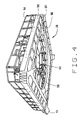
- FIG. 4 is a bottom perspective view of the reactor servicing platform shown in FIG. 2 .
- FIG. 5 is a top perspective schematic view of a reactor servicing platform in accordance with an embodiment of the present invention.
- FIG. 6 is a side schematic view of a reactor servicing platform in accordance with an embodiment of the present invention.
- FIG. 7 is a side schematic view of a reactor servicing platform in accordance with an embodiment of the present invention.
- a reactor servicing platform having a reactor access opening to permit access to the reactor internal components during refueling and maintenance outage operations is described below in detail.
- the reactor servicing platform permits multiple work crews and equipment to simultaneously perform tasks at multiple azimuth locations around a reactor vessel.
- the reactor servicing platform is fabricated from any suitable material(s), for example, aluminum, steel, and thermoplastic and fiber composite materials. Further, the reactor servicing platform has a modular design with major components sized for transport to a reactor refuel floor through an equipment hatch. The reactor servicing is assembled in site in the reactor and can be disassembled and transported to another reactor.
- FIG. 1 is simplified schematic view of a nuclear reactor 10 .
- Reactor 10 includes a reactor pressure vessel 12 positioned in a containment vessel 14 .
- Reactor pressure vessel 12 has a generally cylindrical shape and includes a bottom head 16 and a removable top head (not shown).
- a reactor core 18 is located inside pressure vessel 12 .
- a plurality of control rod drives 20 extend through bottom head 16 and control the position of the control rods (not shown) in core 18 which adjusts the reactivity of core 18 .
- Containment vessel 14 includes a drywell 22 in which pressure vessel 12 is located, and a wetwell 24 .
- a refuel floor 26 extends from a side wall 28 of containment 14 and is located above pressure vessel 12 .
- Refuel floor 26 permits worker access to pressure vessel 12 through an access opening 30 to perform refueling, maintenance, and other servicing functions of pressure vessel 12 .
- a ledge 32 extends from refuel floor 26 into access opening 30 .
- Crane rails 34 are located on an upper surface 36 of refuel floor 26 .
- FIG. 2 is a perspective schematic view of a reactor servicing platform 38 in accordance with an embodiment of the present invention.
- FIG. 3 is a side schematic view of reactor servicing platform 38
- FIG. 4 is a bottom perspective view of reactor servicing platform 38 .
- servicing platform 38 servicing platform 38 includes a frame 40 , a support structure 42 , and a floor 44 covering frame 40 .
- Floor 44 is formed from a plurality of floor panels 46 attached to frame 40 .
- Floor 44 includes a reactor access opening 48 sized to permit access to reactor pressure vessel 12 .
- At least one auxiliary platform 50 extends into access opening 48 .
- Each auxiliary platform 50 is movable along a perimeter of access opening 48 .
- Access opening 48 can be any suitable shape, for example, a circular, elliptical, or polygonal shape.
- a safety rail or fence 52 extends around a perimeter of access opening 48 .
- a safety rail or fence 54 extends around an outer perimeter of floor 44 .
- reactor servicing platform 38 also includes servicing tools, for example, lifting devices 55 , that are movable along a perimeter of access opening 48 .
- Frame 40 includes a plurality of beams 56 , a circular central beam 58 and a plurality of cross-members 60 extending between beams 56 and central beam 58 .
- Circular central beam 58 defines reactor access opening 48 .
- Floor panels 46 attach to beams 56 , central beam 58 , and cross-members 60 to form floor 44 .
- Auxiliary platforms 50 movably couple to upper and lower support rails 62 and 64 that are coupled to circular central beam 58 .
- Upper support rail 62 is coupled to central beam 58 by support brackets 66 .
- Auxiliary platforms 50 include upper rollers 68 and lower rollers 70 that couple to upper and lower support rails 62 and 64 respectively and permit auxiliary platforms 50 to move along support rails 62 and 64 for positioning within reactor access opening 48 .
- servicing tools for example, lifting devices, are movably coupled to upper and lower support rails 62 and 64 .
- Support structure 42 includes support pods 72 attached to frame 40 . In one embodiment support pods rest on upper surface 36 of refuel floor 26 to support servicing platform 38 over pressure vessel 12 .
- FIG. 5 is a top perspective schematic view of a reactor servicing platform 74 in accordance with another embodiment of the present invention.
- Servicing platform 74 is substantially similar to servicing platform 38 , shown in FIGS. 2 , 3 , and 4 , and components in servicing platform 74 that are identical to components of servicing platform 38 are identified in FIG. 5 using the same reference numerals used in FIGS. 2 , 3 , and 4 .
- Servicing platform 74 includes a frame 40 , a floor 44 covering frame 40 , and a support structure 76 .
- Floor 44 includes a reactor access opening 48 sized to permit access to reactor pressure vessel 12 .
- An auxiliary platform 78 is movably coupled to frame 40 and extends across the diameter of access opening 48 .
- Auxiliary platform 78 is movable around the perimeter of access opening 48 .
- Support structure 76 attaches to existing reactor bridges 80 and 82 to suspend servicing platform 74 above reactor pressure vessel 12 (shown in FIG. 1 ).
- FIG. 6 is a side schematic view of a reactor servicing platform 84 in accordance with an embodiment of the present invention.
- Servicing platform 84 is substantially similar to servicing platform 38 , shown in FIGS. 2 , 3 , and 4 , and components in servicing platform 84 that are identical to components of servicing platform 38 are identified in FIG. 6 using the same reference numerals used in FIGS. 2 , 3 , and 4 .
- Servicing platform 84 includes a frame 40 , a floor 44 covering frame 40 , and a support structure 86 .
- Support structure 86 includes support pods 88 attached to frame 40 .
- Support pods 88 are sized and positioned to rest on ledge 32 extending around access opening 30 in refuel floor 26 to support servicing platform 84 over pressure vessel 12 (shown in FIG. 1 ).
- FIG. 7 is a side schematic view of a reactor servicing platform 90 in accordance with an embodiment of the present invention.
- Servicing platform 90 is substantially similar to servicing platform 38 , shown in FIGS. 2 , 3 , and 4 , and components in servicing platform 90 that are identical to components of servicing platform 38 are identified in FIG. 7 using the same reference numerals used in FIGS. 2 , 3 , and 4 .
- Servicing platform 90 includes a frame 40 , a floor 44 covering frame 40 , and a support structure 92 .
- Support structure 92 includes support members 94 attached to frame 40 .
- Each support member 94 includes wheels 96 sized to engage and roll on crane rails 34 (shown in FIG. 1 ) attached to refuel floor upper surface 36 (shown in FIG. 1 ).
- the above described servicing platforms 38 , 74 , 84 , and 90 permit access to the reactor along the radial and tangential directions of the vessel or component.
- the above described servicing platforms 38 , 74 , 84 , and 90 permit radial and tangential alignment simultaneously. Further, the above described servicing platforms 38 , 74 , 84 , and 90 improve plant outage schedules, work productivity, and quality by providing a work platform that permits multiple work crews and equipment to simultaneously perform tasks at multiple azimuths around a reactor vessel
Abstract
Description
Claims (10)
Priority Applications (1)
| Application Number | Priority Date | Filing Date | Title |
|---|---|---|---|
| US11/005,977 US7139357B2 (en) | 2002-02-20 | 2004-12-07 | Reactor servicing platform |
Applications Claiming Priority (2)
| Application Number | Priority Date | Filing Date | Title |
|---|---|---|---|
| US09/683,823 US6856663B2 (en) | 2002-02-20 | 2002-02-20 | Reactor servicing platform |
| US11/005,977 US7139357B2 (en) | 2002-02-20 | 2004-12-07 | Reactor servicing platform |
Related Parent Applications (1)
| Application Number | Title | Priority Date | Filing Date |
|---|---|---|---|
| US09/683,823 Division US6856663B2 (en) | 2002-02-20 | 2002-02-20 | Reactor servicing platform |
Publications (2)
| Publication Number | Publication Date |
|---|---|
| US20060140328A1 US20060140328A1 (en) | 2006-06-29 |
| US7139357B2 true US7139357B2 (en) | 2006-11-21 |
Family
ID=27734952
Family Applications (3)
| Application Number | Title | Priority Date | Filing Date |
|---|---|---|---|
| US09/683,823 Expired - Lifetime US6856663B2 (en) | 2002-02-20 | 2002-02-20 | Reactor servicing platform |
| US10/429,121 Expired - Lifetime US6856664B2 (en) | 2002-02-20 | 2003-05-02 | Reactor servicing platform |
| US11/005,977 Expired - Lifetime US7139357B2 (en) | 2002-02-20 | 2004-12-07 | Reactor servicing platform |
Family Applications Before (2)
| Application Number | Title | Priority Date | Filing Date |
|---|---|---|---|
| US09/683,823 Expired - Lifetime US6856663B2 (en) | 2002-02-20 | 2002-02-20 | Reactor servicing platform |
| US10/429,121 Expired - Lifetime US6856664B2 (en) | 2002-02-20 | 2003-05-02 | Reactor servicing platform |
Country Status (2)
| Country | Link |
|---|---|
| US (3) | US6856663B2 (en) |
| JP (1) | JP4596739B2 (en) |
Cited By (8)
| Publication number | Priority date | Publication date | Assignee | Title |
|---|---|---|---|---|
| US20090020361A1 (en) * | 2003-12-30 | 2009-01-22 | Paul Teichert | Device for enabling access to a structure above ground level |
| US20090245451A1 (en) * | 2008-03-28 | 2009-10-01 | Westinghouse Electric Company, Llc | Mobile rigging structure |
| WO2010030259A1 (en) * | 2008-09-12 | 2010-03-18 | Dbi Operating Company | Thorium-based nuclear reactor and method |
| US20100067644A1 (en) * | 2008-09-12 | 2010-03-18 | D Auvergne Hector A | Thorium-based nuclear reactor and method |
| US8833521B1 (en) * | 2012-03-27 | 2014-09-16 | Troy L. Jude | Rotatably-engaged tree stand and ladder for access there with |
| US9070484B2 (en) | 2007-07-13 | 2015-06-30 | Ge-Hitachi Nuclear Energy Americas Llc | Reactor servicing platform |
| US9666313B2 (en) | 2012-04-17 | 2017-05-30 | Bwxt Mpower, Inc. | Small modular reactor refueling sequence |
| US10546662B2 (en) | 2013-03-15 | 2020-01-28 | Bwxt Mpower, Inc. | Upper vessel transport |
Families Citing this family (13)
| Publication number | Priority date | Publication date | Assignee | Title |
|---|---|---|---|---|
| US20050013401A1 (en) * | 2003-07-02 | 2005-01-20 | Markling Robert E. | Boiling water reactor refuel cavity work platform |
| US20050238130A1 (en) * | 2004-01-29 | 2005-10-27 | Mccann James E | Refueling work platform |
| US20050265510A1 (en) * | 2004-05-14 | 2005-12-01 | Rush Jennings | Multi-plant adaptable boiling water reactor inspection work platform |
| DE102005050942A1 (en) * | 2005-10-21 | 2007-05-03 | Areva Np Gmbh | Method and device for disassembling a built-in part of a nuclear reactor pressure vessel |
| JP2007157849A (en) * | 2005-12-01 | 2007-06-21 | Denso Corp | Manufacturing method of stacked piezoelectric element |
| US8705684B2 (en) * | 2006-11-30 | 2014-04-22 | General Electric Company | Renew process implementation for reactor bottom head |
| FR2968118B1 (en) * | 2010-11-30 | 2012-12-21 | Endel | SHIELDING AND PROTECTIVE DEVICE FOR A NUCLEAR REACTOR TANK |
| US9493957B2 (en) * | 2011-10-24 | 2016-11-15 | The Gsi Group Llc | Catwalk for a grain bin or the like and a plank used in the construction thereof |
| CN102556492A (en) * | 2011-12-30 | 2012-07-11 | 大连理工大学 | Transportation bracket for nuclear containment shell |
| CN105719710A (en) * | 2014-12-01 | 2016-06-29 | 上海核工程研究设计院 | Small modular reactor fuel handling and refueling system |
| CN107476555A (en) * | 2017-07-25 | 2017-12-15 | 广东核电合营有限公司 | A kind of fuel for nuclear power plant factory building service sink workbench and its installation method |
| CN109638695B (en) * | 2018-12-12 | 2024-04-09 | 江苏核电有限公司 | Nuclear power station reactor main pump overhauls rack |
| GB2593258A (en) * | 2020-12-03 | 2021-09-22 | Rolls Royce Plc | Nuclear power generation system |
Citations (24)
| Publication number | Priority date | Publication date | Assignee | Title |
|---|---|---|---|---|
| US3393026A (en) | 1963-11-22 | 1968-07-16 | Fairey Eng | Rotary bearing arrangements for supporting large heavy objects, for example rotatable sections of shielding in nuclear reactors |
| US3960242A (en) | 1972-12-01 | 1976-06-01 | Whiting Corporation | Orbital service bridge |
| US3967741A (en) | 1974-02-15 | 1976-07-06 | Fried. Krupp Gesellschaft Mit Beschrankter Haftung | Device for moving fuel elements and control bars from one place to another place in a core reactor |
| US3994365A (en) | 1974-11-04 | 1976-11-30 | Georgia-Pacific Corporation | Apparatus for positioning person within container tank |
| US4078969A (en) | 1976-08-13 | 1978-03-14 | The United States Government As Represented By The U. S. Department Of Energy | Core disruptive accident margin seal |
| US4080254A (en) | 1976-04-28 | 1978-03-21 | The United States Of America As Represented By The United States Department Of Energy | Plug-to-plug gas transfer system |
| FR2373858A1 (en) | 1976-12-07 | 1978-07-07 | Westinghouse Electric Corp | NUCLEAR FUEL HANDLING EQUIPMENT |
| US4115193A (en) | 1975-04-25 | 1978-09-19 | The United States Of America As Represented By The United States Department Of Energy | Nuclear reactor pressure vessel support system |
| US4192558A (en) | 1976-12-07 | 1980-03-11 | Westinghouse Electric Corp. | Self-lubricating bearing |
| US4200172A (en) | 1978-04-14 | 1980-04-29 | Westinghouse Electric Corp. | Radiation shielded movable work station apparatus |
| US4288292A (en) | 1977-05-25 | 1981-09-08 | The United States Of America As Represented By The United States Department Of Energy | Connecting apparatus for limited rotary of rectilinear motion (II) |
| JPS57161273A (en) | 1981-03-31 | 1982-10-04 | Tokyo Shibaura Electric Co | Automatic disassembling apparatus of pressure container of atomic reactor |
| US4401619A (en) | 1980-12-23 | 1983-08-30 | Rockwell International Corporation | Nuclear reactor sealing system |
| US4505874A (en) | 1982-03-08 | 1985-03-19 | Combustion Engineering Co., Inc. | Vessel inspection boom |
| US4639351A (en) | 1983-03-23 | 1987-01-27 | Kraftwerk Union Aktiengesellschaft | Repair device for a reactor pressure vessel |
| US5183625A (en) | 1990-04-02 | 1993-02-02 | Framatome | Removable platform for working inside a casing of a pressurizer of a pressurized-water nuclear reactor |
| US5241572A (en) * | 1991-05-31 | 1993-08-31 | British Nuclear Fuels Plc | Apparatus for locating a floatable platform |
| US5254835A (en) | 1991-07-16 | 1993-10-19 | General Electric Company | Robotic welder for nuclear boiling water reactors |
| US5291531A (en) | 1992-12-30 | 1994-03-01 | Combustion Engineering, Inc. | Auxiliary platform for boiling water reactors |
| US5351277A (en) | 1990-04-13 | 1994-09-27 | Hitachi, Ltd. | Method of constructing top slab of nuclear reactor container and nuclear reactor container constructed by the method |
| JPH07113896A (en) | 1993-10-18 | 1995-05-02 | Toshiba Corp | Reactor service platform |
| US5600686A (en) | 1994-08-16 | 1997-02-04 | Siemens Aktiengesellschaft | Method for replacing a component located in the interior of a containment of a nuclear reactor |
| US5687207A (en) | 1996-04-02 | 1997-11-11 | Westinghouse Electric Corporation | Refueling machine |
| US5774513A (en) | 1997-01-14 | 1998-06-30 | Combustion Engineering, Inc. | Head area cable tray bridge |
Family Cites Families (7)
| Publication number | Priority date | Publication date | Assignee | Title |
|---|---|---|---|---|
| US3817348A (en) * | 1972-07-10 | 1974-06-18 | Transfer Systems | Refueling bridge with service elevator for well wall maintenance |
| US4120378A (en) * | 1977-03-07 | 1978-10-17 | Mills Ernest E | Movable work support for cylindrical structures |
| US4427623A (en) * | 1981-07-27 | 1984-01-24 | General Electric Company | Automatic fuel transfer apparatus and method |
| US5085824A (en) * | 1991-01-31 | 1992-02-04 | General Electric Company | Nuclear refueling platform drive system |
| GB9407257D0 (en) * | 1993-04-22 | 1994-06-08 | Ici Plc | Vaporisation of liquids |
| US5369676A (en) * | 1993-08-19 | 1994-11-29 | General Electric Company | Reactor refueling mechanism |
| FR2719697B1 (en) * | 1994-05-05 | 1996-08-02 | Framatome Sa | Loading machine for fuel assemblies at the heart of a nuclear reactor having removable guide beams. |
-
2002
- 2002-02-20 US US09/683,823 patent/US6856663B2/en not_active Expired - Lifetime
-
2003
- 2003-02-19 JP JP2003040449A patent/JP4596739B2/en not_active Expired - Lifetime
- 2003-05-02 US US10/429,121 patent/US6856664B2/en not_active Expired - Lifetime
-
2004
- 2004-12-07 US US11/005,977 patent/US7139357B2/en not_active Expired - Lifetime
Patent Citations (24)
| Publication number | Priority date | Publication date | Assignee | Title |
|---|---|---|---|---|
| US3393026A (en) | 1963-11-22 | 1968-07-16 | Fairey Eng | Rotary bearing arrangements for supporting large heavy objects, for example rotatable sections of shielding in nuclear reactors |
| US3960242A (en) | 1972-12-01 | 1976-06-01 | Whiting Corporation | Orbital service bridge |
| US3967741A (en) | 1974-02-15 | 1976-07-06 | Fried. Krupp Gesellschaft Mit Beschrankter Haftung | Device for moving fuel elements and control bars from one place to another place in a core reactor |
| US3994365A (en) | 1974-11-04 | 1976-11-30 | Georgia-Pacific Corporation | Apparatus for positioning person within container tank |
| US4115193A (en) | 1975-04-25 | 1978-09-19 | The United States Of America As Represented By The United States Department Of Energy | Nuclear reactor pressure vessel support system |
| US4080254A (en) | 1976-04-28 | 1978-03-21 | The United States Of America As Represented By The United States Department Of Energy | Plug-to-plug gas transfer system |
| US4078969A (en) | 1976-08-13 | 1978-03-14 | The United States Government As Represented By The U. S. Department Of Energy | Core disruptive accident margin seal |
| FR2373858A1 (en) | 1976-12-07 | 1978-07-07 | Westinghouse Electric Corp | NUCLEAR FUEL HANDLING EQUIPMENT |
| US4192558A (en) | 1976-12-07 | 1980-03-11 | Westinghouse Electric Corp. | Self-lubricating bearing |
| US4288292A (en) | 1977-05-25 | 1981-09-08 | The United States Of America As Represented By The United States Department Of Energy | Connecting apparatus for limited rotary of rectilinear motion (II) |
| US4200172A (en) | 1978-04-14 | 1980-04-29 | Westinghouse Electric Corp. | Radiation shielded movable work station apparatus |
| US4401619A (en) | 1980-12-23 | 1983-08-30 | Rockwell International Corporation | Nuclear reactor sealing system |
| JPS57161273A (en) | 1981-03-31 | 1982-10-04 | Tokyo Shibaura Electric Co | Automatic disassembling apparatus of pressure container of atomic reactor |
| US4505874A (en) | 1982-03-08 | 1985-03-19 | Combustion Engineering Co., Inc. | Vessel inspection boom |
| US4639351A (en) | 1983-03-23 | 1987-01-27 | Kraftwerk Union Aktiengesellschaft | Repair device for a reactor pressure vessel |
| US5183625A (en) | 1990-04-02 | 1993-02-02 | Framatome | Removable platform for working inside a casing of a pressurizer of a pressurized-water nuclear reactor |
| US5351277A (en) | 1990-04-13 | 1994-09-27 | Hitachi, Ltd. | Method of constructing top slab of nuclear reactor container and nuclear reactor container constructed by the method |
| US5241572A (en) * | 1991-05-31 | 1993-08-31 | British Nuclear Fuels Plc | Apparatus for locating a floatable platform |
| US5254835A (en) | 1991-07-16 | 1993-10-19 | General Electric Company | Robotic welder for nuclear boiling water reactors |
| US5291531A (en) | 1992-12-30 | 1994-03-01 | Combustion Engineering, Inc. | Auxiliary platform for boiling water reactors |
| JPH07113896A (en) | 1993-10-18 | 1995-05-02 | Toshiba Corp | Reactor service platform |
| US5600686A (en) | 1994-08-16 | 1997-02-04 | Siemens Aktiengesellschaft | Method for replacing a component located in the interior of a containment of a nuclear reactor |
| US5687207A (en) | 1996-04-02 | 1997-11-11 | Westinghouse Electric Corporation | Refueling machine |
| US5774513A (en) | 1997-01-14 | 1998-06-30 | Combustion Engineering, Inc. | Head area cable tray bridge |
Non-Patent Citations (1)
| Title |
|---|
| Merriam Webster's Collegiate Dictionary, 10th Edition, p. 891. * |
Cited By (11)
| Publication number | Priority date | Publication date | Assignee | Title |
|---|---|---|---|---|
| US20090020361A1 (en) * | 2003-12-30 | 2009-01-22 | Paul Teichert | Device for enabling access to a structure above ground level |
| US8083029B2 (en) * | 2003-12-30 | 2011-12-27 | Pp Energy Aps | Device for enabling access to a structure above ground level |
| US20120090917A1 (en) * | 2003-12-30 | 2012-04-19 | Pp Energy Aps | Device for enabling access to a structure above ground level |
| US8534421B2 (en) * | 2003-12-30 | 2013-09-17 | Pp Energy Aps | Device for enabling access to a structure above ground level |
| US9070484B2 (en) | 2007-07-13 | 2015-06-30 | Ge-Hitachi Nuclear Energy Americas Llc | Reactor servicing platform |
| US20090245451A1 (en) * | 2008-03-28 | 2009-10-01 | Westinghouse Electric Company, Llc | Mobile rigging structure |
| WO2010030259A1 (en) * | 2008-09-12 | 2010-03-18 | Dbi Operating Company | Thorium-based nuclear reactor and method |
| US20100067644A1 (en) * | 2008-09-12 | 2010-03-18 | D Auvergne Hector A | Thorium-based nuclear reactor and method |
| US8833521B1 (en) * | 2012-03-27 | 2014-09-16 | Troy L. Jude | Rotatably-engaged tree stand and ladder for access there with |
| US9666313B2 (en) | 2012-04-17 | 2017-05-30 | Bwxt Mpower, Inc. | Small modular reactor refueling sequence |
| US10546662B2 (en) | 2013-03-15 | 2020-01-28 | Bwxt Mpower, Inc. | Upper vessel transport |
Also Published As
| Publication number | Publication date |
|---|---|
| US20030156676A1 (en) | 2003-08-21 |
| US6856664B2 (en) | 2005-02-15 |
| JP4596739B2 (en) | 2010-12-15 |
| US20060140328A1 (en) | 2006-06-29 |
| US6856663B2 (en) | 2005-02-15 |
| US20030227993A1 (en) | 2003-12-11 |
| JP2003255077A (en) | 2003-09-10 |
Similar Documents
| Publication | Publication Date | Title |
|---|---|---|
| US7139357B2 (en) | Reactor servicing platform | |
| CA1306314C (en) | Apparatus and process for nuclear reactor instrumentation device | |
| US5239564A (en) | Process for dismantling an irradiated component of a nuclear reactor by the cutting of its wall | |
| US6533640B1 (en) | Ultra high pressure abrasive waterjet cutting apparatus | |
| US20020157327A1 (en) | Method of handling a structure and equipment of handling the same | |
| ZA200208929B (en) | Method and device for loading the core of a nuclear reactor with fuel assemblies. | |
| US5526384A (en) | Fueling machine for fuel assemblies for the core of a nuclear reactor, having removable guide beams | |
| CA2081644C (en) | Method for erection of absorber towers using jacking system | |
| US20240021330A1 (en) | Floating maintenance platform for nuclear facility | |
| NL8301984A (en) | STEEL CONSTRUCTION. | |
| KR830001008B1 (en) | Reactor internal structure and control rod handling device | |
| US20050013401A1 (en) | Boiling water reactor refuel cavity work platform | |
| JP2011196903A (en) | Nuclear reactor platform and nuclear reactor inspection method | |
| JPH07113896A (en) | Reactor service platform | |
| JPS629706B2 (en) | ||
| US20230162877A1 (en) | Platform and platform system for nuclear power plant | |
| KR200223713Y1 (en) | Reactor Protection Cover | |
| CA2766470C (en) | Nuclear reactor feeder removal process | |
| EP0978126B1 (en) | A nuclear reactor device and a method to construct a nuclear reactor device | |
| KR960013586B1 (en) | Method for constructing huge modules, and a module fabricated by the method | |
| CA2766440C (en) | Feeder platform for nuclear reactor | |
| JP2004325219A (en) | Platform for work in nuclear reactor, and working method in nuclear reactor | |
| US10090071B2 (en) | Systems and methods for disposing of one or more radioactive components from nuclear reactors of nuclear plants | |
| JPH0217088Y2 (en) | ||
| JPH09166684A (en) | Structure of pool in reactor building |
Legal Events
| Date | Code | Title | Description |
|---|---|---|---|
| STCF | Information on status: patent grant |
Free format text: PATENTED CASE |
|
| FPAY | Fee payment |
Year of fee payment: 4 |
|
| REMI | Maintenance fee reminder mailed | ||
| FPAY | Fee payment |
Year of fee payment: 8 |
|
| SULP | Surcharge for late payment |
Year of fee payment: 7 |
|
| FEPP | Fee payment procedure |
Free format text: MAINTENANCE FEE REMINDER MAILED (ORIGINAL EVENT CODE: REM.) |
|
| FEPP | Fee payment procedure |
Free format text: 11.5 YR SURCHARGE- LATE PMT W/IN 6 MO, LARGE ENTITY (ORIGINAL EVENT CODE: M1556); ENTITY STATUS OF PATENT OWNER: LARGE ENTITY |
|
| MAFP | Maintenance fee payment |
Free format text: PAYMENT OF MAINTENANCE FEE, 12TH YEAR, LARGE ENTITY (ORIGINAL EVENT CODE: M1553); ENTITY STATUS OF PATENT OWNER: LARGE ENTITY Year of fee payment: 12 |
|
| AS | Assignment |
Owner name: GE HITACHI NUCLEAR ENERGY AMERICAS LLC, NORTH CAROLINA Free format text: ASSIGNMENT OF ASSIGNORS INTEREST;ASSIGNOR:GENERAL ELECTRIC COMPANY;REEL/FRAME:065507/0098 Effective date: 20231109 |