US7136090B1 - Communications system - Google Patents
Communications system Download PDFInfo
- Publication number
- US7136090B1 US7136090B1 US10/049,253 US4925302A US7136090B1 US 7136090 B1 US7136090 B1 US 7136090B1 US 4925302 A US4925302 A US 4925302A US 7136090 B1 US7136090 B1 US 7136090B1
- Authority
- US
- United States
- Prior art keywords
- location
- image
- observation zone
- way mirror
- participant
- Prior art date
- Legal status (The legal status is an assumption and is not a legal conclusion. Google has not performed a legal analysis and makes no representation as to the accuracy of the status listed.)
- Expired - Fee Related, expires
Links
- 238000004891 communication Methods 0.000 title claims description 23
- 230000000007 visual effect Effects 0.000 claims description 36
- 239000011521 glass Substances 0.000 claims description 11
- 230000000694 effects Effects 0.000 claims description 4
- 230000003993 interaction Effects 0.000 claims description 4
- 230000009471 action Effects 0.000 claims description 3
- 230000001360 synchronised effect Effects 0.000 claims description 2
- 239000000463 material Substances 0.000 description 10
- 210000003128 head Anatomy 0.000 description 9
- 238000000034 method Methods 0.000 description 9
- 238000013519 translation Methods 0.000 description 4
- 230000005540 biological transmission Effects 0.000 description 2
- 238000004590 computer program Methods 0.000 description 2
- 230000000875 corresponding effect Effects 0.000 description 2
- 230000004044 response Effects 0.000 description 2
- 238000012549 training Methods 0.000 description 2
- 241001422033 Thestylus Species 0.000 description 1
- 230000003213 activating effect Effects 0.000 description 1
- 238000004458 analytical method Methods 0.000 description 1
- 230000004888 barrier function Effects 0.000 description 1
- 230000008859 change Effects 0.000 description 1
- 230000002596 correlated effect Effects 0.000 description 1
- 230000008451 emotion Effects 0.000 description 1
- 230000014509 gene expression Effects 0.000 description 1
- 230000002452 interceptive effect Effects 0.000 description 1
- 238000004519 manufacturing process Methods 0.000 description 1
- 230000003278 mimic effect Effects 0.000 description 1
- 230000002688 persistence Effects 0.000 description 1
- 238000012545 processing Methods 0.000 description 1
- 230000000717 retained effect Effects 0.000 description 1
- 238000012552 review Methods 0.000 description 1
- 230000001960 triggered effect Effects 0.000 description 1
- PICXIOQBANWBIZ-UHFFFAOYSA-N zinc;1-oxidopyridine-2-thione Chemical class [Zn+2].[O-]N1C=CC=CC1=S.[O-]N1C=CC=CC1=S PICXIOQBANWBIZ-UHFFFAOYSA-N 0.000 description 1
Images


Classifications
-
- G—PHYSICS
- G03—PHOTOGRAPHY; CINEMATOGRAPHY; ANALOGOUS TECHNIQUES USING WAVES OTHER THAN OPTICAL WAVES; ELECTROGRAPHY; HOLOGRAPHY
- G03B—APPARATUS OR ARRANGEMENTS FOR TAKING PHOTOGRAPHS OR FOR PROJECTING OR VIEWING THEM; APPARATUS OR ARRANGEMENTS EMPLOYING ANALOGOUS TECHNIQUES USING WAVES OTHER THAN OPTICAL WAVES; ACCESSORIES THEREFOR
- G03B15/00—Special procedures for taking photographs; Apparatus therefor
- G03B15/08—Trick photography
- G03B15/10—Trick photography using back-projection, i.e. blending artificial background with real foreground
-
- H—ELECTRICITY
- H04—ELECTRIC COMMUNICATION TECHNIQUE
- H04N—PICTORIAL COMMUNICATION, e.g. TELEVISION
- H04N13/00—Stereoscopic video systems; Multi-view video systems; Details thereof
- H04N13/10—Processing, recording or transmission of stereoscopic or multi-view image signals
- H04N13/194—Transmission of image signals
-
- H—ELECTRICITY
- H04—ELECTRIC COMMUNICATION TECHNIQUE
- H04N—PICTORIAL COMMUNICATION, e.g. TELEVISION
- H04N13/00—Stereoscopic video systems; Multi-view video systems; Details thereof
- H04N13/20—Image signal generators
- H04N13/204—Image signal generators using stereoscopic image cameras
- H04N13/239—Image signal generators using stereoscopic image cameras using two 2D image sensors having a relative position equal to or related to the interocular distance
-
- H—ELECTRICITY
- H04—ELECTRIC COMMUNICATION TECHNIQUE
- H04N—PICTORIAL COMMUNICATION, e.g. TELEVISION
- H04N13/00—Stereoscopic video systems; Multi-view video systems; Details thereof
- H04N13/30—Image reproducers
- H04N13/302—Image reproducers for viewing without the aid of special glasses, i.e. using autostereoscopic displays
- H04N13/305—Image reproducers for viewing without the aid of special glasses, i.e. using autostereoscopic displays using lenticular lenses, e.g. arrangements of cylindrical lenses
-
- H—ELECTRICITY
- H04—ELECTRIC COMMUNICATION TECHNIQUE
- H04N—PICTORIAL COMMUNICATION, e.g. TELEVISION
- H04N13/00—Stereoscopic video systems; Multi-view video systems; Details thereof
- H04N13/30—Image reproducers
- H04N13/332—Displays for viewing with the aid of special glasses or head-mounted displays [HMD]
- H04N13/337—Displays for viewing with the aid of special glasses or head-mounted displays [HMD] using polarisation multiplexing
-
- H—ELECTRICITY
- H04—ELECTRIC COMMUNICATION TECHNIQUE
- H04N—PICTORIAL COMMUNICATION, e.g. TELEVISION
- H04N13/00—Stereoscopic video systems; Multi-view video systems; Details thereof
- H04N13/30—Image reproducers
- H04N13/332—Displays for viewing with the aid of special glasses or head-mounted displays [HMD]
- H04N13/341—Displays for viewing with the aid of special glasses or head-mounted displays [HMD] using temporal multiplexing
-
- H—ELECTRICITY
- H04—ELECTRIC COMMUNICATION TECHNIQUE
- H04N—PICTORIAL COMMUNICATION, e.g. TELEVISION
- H04N7/00—Television systems
- H04N7/14—Systems for two-way working
- H04N7/141—Systems for two-way working between two video terminals, e.g. videophone
- H04N7/142—Constructional details of the terminal equipment, e.g. arrangements of the camera and the display
- H04N7/144—Constructional details of the terminal equipment, e.g. arrangements of the camera and the display camera and display on the same optical axis, e.g. optically multiplexing the camera and display for eye to eye contact
-
- H—ELECTRICITY
- H04—ELECTRIC COMMUNICATION TECHNIQUE
- H04N—PICTORIAL COMMUNICATION, e.g. TELEVISION
- H04N13/00—Stereoscopic video systems; Multi-view video systems; Details thereof
- H04N13/10—Processing, recording or transmission of stereoscopic or multi-view image signals
- H04N13/106—Processing image signals
- H04N13/161—Encoding, multiplexing or demultiplexing different image signal components
-
- H—ELECTRICITY
- H04—ELECTRIC COMMUNICATION TECHNIQUE
- H04N—PICTORIAL COMMUNICATION, e.g. TELEVISION
- H04N13/00—Stereoscopic video systems; Multi-view video systems; Details thereof
- H04N13/20—Image signal generators
- H04N13/296—Synchronisation thereof; Control thereof
-
- H—ELECTRICITY
- H04—ELECTRIC COMMUNICATION TECHNIQUE
- H04N—PICTORIAL COMMUNICATION, e.g. TELEVISION
- H04N13/00—Stereoscopic video systems; Multi-view video systems; Details thereof
- H04N13/30—Image reproducers
- H04N13/363—Image reproducers using image projection screens
-
- H—ELECTRICITY
- H04—ELECTRIC COMMUNICATION TECHNIQUE
- H04N—PICTORIAL COMMUNICATION, e.g. TELEVISION
- H04N13/00—Stereoscopic video systems; Multi-view video systems; Details thereof
- H04N13/30—Image reproducers
- H04N13/366—Image reproducers using viewer tracking
-
- H—ELECTRICITY
- H04—ELECTRIC COMMUNICATION TECHNIQUE
- H04N—PICTORIAL COMMUNICATION, e.g. TELEVISION
- H04N13/00—Stereoscopic video systems; Multi-view video systems; Details thereof
- H04N13/30—Image reproducers
- H04N13/398—Synchronisation thereof; Control thereof
Definitions
- This invention relates to a communications system which is particularly suitable for, but not limited to, video conferencing in which eye contact with a transmitted life-size image of a person superimposed into a three dimensional setting can be achieved.
- Video conferencing these systems use a network connection, such as ISDN, to transmit video between two locations.
- Most systems use a video monitor to display the people at the distant location and have a camera positioned on top of the monitor to capture an image of the users in the home location for transmission to the distant location.
- the user in the home location views the remote location displayed on a screen directly in front of him or her.
- This provides the user with a ‘telepresence’ by presenting a view of the remote location as if they were actually there.
- the people in the remote location will view the user in the home location as a life-size image superimposed into a position behind a lectern or seated at a table.
- the superimposed life-size image is positioned so that the camera is matched to the field of view for the telepresence of the user in the home location. Since the people in the remote location see a life-size image of a person who has a telepresence for natural human communication, we call this technique “teleportation”.
- This eye to eye contact with the teleported person makes it easier to establish a sense of presence which encourages more natural communication.
- people can be more expressive and draw upon human gestures and expressions to communicate emotions and feelings.
- this invention creates a new form of communication that has been coined a “teleportation conference”.
- This invention provides a system for achieving eye to eye communication by matching the position of cameras with the relative position of the eyes of the images of the people displayed on screens.
- Embodiments of the present invention reside in, but are not limited to, a communications system for linking participants at two separate locations, comprising: first and second locations each provided with at least one real time image capturing device, at least one image projecting device, an observation zone for occupation by a participant at that location and a two-way mirror through which images are viewed, the image capturing device(s) at each location being:
- the visual depth means may be constituted by one or more suitably located objects or a further image display (e.g. an image or images projected onto a screen or backdrop) located beyond the two-way mirror so as to be prominently visible to the observer at that location.
- a further image display e.g. an image or images projected onto a screen or backdrop
- three dimensional setting is to be understood in terms of an arrangement which gives the observer the impression of the remotely-derived image being positioned within a three-dimensional volume beyond the two-way mirror.
- the three dimensional setting is implemented by positioning the remotely-derived image (which may be flat or stereoscopic) in a plane spaced, along the line of sight of the viewer, from one or more further planes at which a further image or images (e.g. scenery) is displayed, the further image(s) being flat or stereoscopic.
- the invention may comprise a home location connected by a network to one or more remote locations with each location having an arrangement of an image-capturing device in the form of a video camera, a two way mirror and an image display.
- the video camera can be any device that captures moving images of the user.
- the camera may output the moving images in a standard video format or a format optimised for a network, such as internet protocol for transmission over the internet.
- the two way mirror can be a semi-transparent element comprising for example a partially mirrored glass, plastic or film material or other form of beam-splitting arrangement.
- the two way mirror may be laminated with one or more sheets of glass or plastic to maintain a flat surface.
- the image display can be a rear projection screen, a front projection screen, a retroreflective surface or a large display screen, such as a plasma screen, LCD screen or monitor.
- a user seated at a table looks forward to see the life-size image of a person from another location called the remote location.
- a two way mirror positioned in front of the user is angled to reflect an image of a person displayed on an image display. So that the image as seen by the viewer at one location is not a mirror image of the participant at the remote location, it may be necessary to flip the image laterally by video processing or by mounting a small mirror in front of the camera lens.
- the configurations can be arranged so that the two way mirror is angled down to reflect an image display positioned below or angled up to reflect an image display positioned above.
- the image display and the mirror are configured so that the reflected image of the person on the image display appears to be on the other side of a table or lectern.
- the teleported person may appear to be seated in a chair and the camera may be located in a high back with a camera facing towards the user to capture the image of the user in the home location.
- the camera may be located in a draped backdrop behind the lectern. In either configuration the position of the eyes of the teleported person is displayed in a position to match the line of sight as captured by the camera.
- the visual person(s) to person(s) link between locations may be supplemented by a computer link between the locations.
- the user(s) may have a computer monitor positioned in front of him or her so that he or she could control computer programs containing content to be shared with the remote person(s).
- the computer in the home location may be networked by the Internet, telecommunications connection or private network with a compatible computer in the remote location. Through specialist software and a network connection the images displayed on the screen in the home location can be controlled to be displayed on a monitor in front of the remote person and/or on a screen to be viewed by an audience in the remote location.
- the users in each location will be able to use a stylus to make notations on the screen which will be visualised on the computer screens in both the home and the remote locations.
- One application of the invention may, for instance, be for a teleportation meeting between a banker in a national centre and a customer in a branch of the bank whereas the banker would select relevant graphics and forms within a custom computer program. Through the teleportation visual display of face to face communication the banker and the customer would discuss the displayed graphic and financial material. Information that is of interest to the customer could be printed by a small printer next to the customer for taking away for further review and consideration.
- the banker could help the customer to fill in forms by typing in information or using the stylus to check appropriate boxes while maintaining a personal eye to eye communication to provide assurance and gauge responses.
- the completed form could be printed in the branch bank and signed by the customer for posting back to the national bank centre.
- the person in the home location would be displayed at a lectern in a remote location.
- the visual content displayed on the computer screen in the home location would be networked to the remote location for display on a large screen that would be in clear view of an audience.
- the invention would be used for teaching, training or corporate presentations where the audience would be interested in both seeing the presenter and seeing the content of the presentation. With the use of a stylus the presenter would be able to make notations that would highlight content in a prepared presentation.
- the screen in front of the audience could be an “interactive board” that would have the feature of registering any notations made on the board as a computer input.
- the notations on the screen would be networked to the presenter's computer so that he or she could see a display of any input by the audience in the remote location.
- a substantially full figure from head to toe is displayed at substantially life-size.
- the figure can be displayed in a theatre where the teleported person appears to be on the stage.
- the teleported person may be able to see a large screen display of the audience so that he/she can interact through natural conversation with members of the audience. In this way, dignitaries, performers, musicians, sports stars and celebrities could be brought into face to face contact with audiences around the world.
- the user in the home location may for example see the three dimensional setting of a conference room through the two way mirror and an image of the distant user superimposed into a position behind the table in a plane that is in front of a chair.
- the chair and table serve to provide visual depth cues so that the image of the distant user is seen in a three dimensional setting.
- a camera on the user at each location views through the two way mirror to capture an image of the user.
- the video or computer image has the background dropped out to black so that the only image being displayed on the screen is the image of the user.
- This black background can be achieved by shooting the user against a black background; by using a chromakey technique to replace a colour, such as blue, with a black background or by using a retroreflective material with a key light positioned close to the camera lens.
- the invention can be configured to have more than two locations participating in the teleportation conference with each location having separate image displays for each person transmitted from the remote locations. In these configurations a separate camera is used for each view of the user.
- the two cameras are positioned above the two way mirror so that their field of view covers a reflection of the user in the two way mirror.
- the exact location of the two cameras is determined by the position of the eyes of the user in the remote location.
- a head tracking system determines the exact position of the eyes of the user in the remote location and the co-ordinates are transmitted to the home location. In the home location the cameras are moved to the selected position above the mirror to match the relative position of the remote user behind the two way mirror.
- the screen comprises retroreflective material and the images are front projected.
- the two projectors use single lenses and the projectors are positioned so that the focal points of the reflected images match to the positions of the two eyes of the user.
- the co-ordinates produced by the head tracking device are used to position the projectors in the remote location.
- the projectors are held in a translation stage that moves to a position to be at the reflected focal point from the retroreflective surface. In this way the user will see an autostereoscopic image.
- Another method for solving this problem is to have shutters on both the cameras and the projectors that are synchronised to alternate between projecting the image of the remote location and capturing the image in the home location.
- Another method for achieving stereoscopic images is to project two images obtained using two separate cameras at the remote location that are offset laterally to provide a stereoscopic pair with polarising filters set at 90 degrees to each other onto a rear projection screen that retains the polarity of light as it passes through the screen. While normal rear projection screen materials diffuse polarised light, the polarisation of light is retained by using clear screen material with a fresnel lens on one side and a lenticular array on the other.
- the stereoscopic pair of images projected on the high gain rear projection screen is reflected by the two way mirror and the resulting stereoscopic images may be viewed through 3D polarised glasses.
- the same stereoscopic visual effect can be achieved by using glasses or goggles that use LCD shutters to alternate between left and right views of the participant from a pair of cameras in the other location.
- the screen could be of a type that would diffuse polarised light.
- the shutter glasses could be used with a CRT monitor, LCD monitor, plasma screen or other type of electronic image display system that could alternate the display of the left and right images, the arrangement being such that the displayed images are reflected by the two way mirror so as to appear to be within the 3 dimensional setting located beyond the two way mirror.
- a method for achieving stereoscopic effect without the use of polarising glasses or LCD goggles is to use a lenticular screen on a monitor which displays a set of offset views for reflection by the two way mirror so as to appear to be within the three dimensional setting.
- This method is ideal for autostereoscopic viewing from several positions simultaneously.
- the size of displays with this technique is governed by the size of high resolution monitors available.
- the person may be projected onto the screen with a black background. Their stereoscopic image will be reflected to appear within the three dimensional space in front of the viewer. In this manner the person and any objects captured by the cameras will appear to have true depth as they are seen in the three dimensional space. Unlike the single image that will appear to be within the single plane of the reflected image, the person in the stereoscopic image could appear to move closer and further away within the three dimensional space behind the two way mirror and could even appear to reach forward of the two way mirror.
- a particularly advantageous feature of the invention is that a life-size image of a person in a remote location may be made to appear in a three dimensional setting that may include objects within the image area. It is then possible to assign functions to be performed when the image of the remote person intersects with the physical location of one of the objects, i.e. actions on the part of the user in the remote location may be correlated with physical objects in the three dimensional setting at the home location so as to give the impression of interaction of the remotely-captured image with the physical objects at the home location. As an example, a remote person could trigger a function by reaching to the location of a button within the image area.
- the function could be triggered by a software application that would recognise the movement of a hand as it entered a zone dedicated to a predetermined function. In this way a remote person could perform functions in a manner similar to actually being in the remote location.
- Another method for registering a function is for the person in the home location to make physical contact with an object in the home location.
- the physical contact will be registered as a set of measurable pressures and/or physical movements. These registered physical pressures and/or movements will be activated in the remote location on a similar object to mimic the action taken in the home location. This will result in a coordinated display of an image of the person in the remote location activating actual physical movement or physical change to objects in the three dimensional space. This effect can be very useful in training or demonstrations.
- the invention includes within its scope a system in which there is at least one further location so arranged that a person at each location is able to communicate at least visually with a person at at least one, and preferably at each, other location
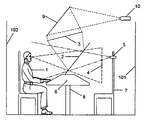
- FIG. 1 shows one system in accordance with the invention with a user seated at a table with a two way mirror that reflects an image of a user in a remote location and provides a view through the mirror to a setting with a chair so that the image of the remote user is superimposed into the scene and a camera captures an image of the user through the two way mirror.
- FIG. 2 shows the system in the configuration in the remote location with a mirror image of all of the same features of the home location.
- FIG. 3 shows the system with a shorter person at the home location.
- FIG. 4 shows the system in the configuration of the remote location with the camera on the user in a lower position in order to match the height of the eyes of the user in the home location.
- FIG. 5 shows the system in a configuration with the image display below the two way mirror and the superimposed image of the remote person positioned in a chair.
- FIG. 6 shows the system with the image display housed in a lectern with the superimposed remote person in front of a curtain backdrop.
- FIG. 7 shows an embodiment of the system used for autostereoscopic viewing of a person in a remote location with a pair of projectors projecting an image on a retroreflective surface and a pair of cameras capturing the reflected image of the user.
- FIG. 8 shows the embodiment of the system in the autostereoscopic configuration for the remote location.
- FIG. 9 shows the system with the user in the home location with a closer viewing position with an adjusted position of the projectors to match the relative distance from the retroreflective screen.
- FIG. 10 shows the system in the remote location with the camera on the user moved in closer to match the relative distance of the user in the home position to the user in the remote location.
- FIG. 11 shows an embodiment of the system where the person in the home location is a head to toe figure displayed on a screen positioned above the two way mirror so that it is superimposed onto a stage and is viewed by an audience.
- FIG. 12 shows another configuration of the system in a theatre setting where the two way mirror is angled down to reflect a screen below which has an image of a full head to toe figure.
- FIG. 13 shows a configuration of the system where a full height view of the user is captured by camera in the home location and the user has a view of an audience in a remote location displayed on a large screen.
- FIG. 14 shows the system in a configuration of an exhibition stand where group of standing people can view a superimposed image of a user from the home location.
- FIG. 15 shows a top view of the system in the configuration for an exhibition stand where the camera angle of view captures an image of a group of people.
- FIG. 16 shows the top view of the system at the home location where the user can see an image positioned at an angle of view that matches the angle of view of the camera in the remote location on the group of people looking into the exhibition stand.
- FIG. 17 shows a top view of the system in a configuration at an exhibition stand with two cameras to cover a wider area showing a group of people.
- FIG. 18 shows a top view of the system in a configuration at the home location with two screens that match the cameras angles of view of the group at the remote location.
- FIG. 19 shows a top view of triangular table that represents the layout for a teleportation conference for three people.
- FIG. 20 shows the top view of the system in a configuration for the home location for a three way teleportation conference.
- FIG. 21 shows the top view of the system in a configuration of the first remote location for a three way teleportation conference.
- FIG. 22 shows the top view of the system in a configuration of the second remote location for a three way teleportation conference.
- FIG. 23 shows a configuration with a rear projection screen for displaying an image of a remote person and a control object in the plane of the reflected image.
- FIG. 24 shows a configuration with a rear projection screen displaying a stereoscopic image with a number of control objects at different depths.
- a user 1 is in the home location for a teleportation conference.
- the user 1 looks forward to see an image on a screen 3 that is reflected off a beam splitter in the form of a two way mirror 2 .
- the two way mirror 2 and the screen 3 are aligned so that the reflected image is superimposed in a three dimensional setting behind table 8 at position 4 which appears to be in front of the chair 7 and background wall 101 , the chair and table serving as visible depth cues for the observer.
- the rear projection screen 3 has an image projected from projector 10 that is reflected off mirror 9 .
- a camera 5 captures an image of the user 1 through the two way mirror 2 .
- the camera views the participant directly along a line of sight which passes through the two-way mirror and through the image 4 .
- the user 1 is viewed against a background wall 102 which is either black, a colour for chromakey or a retroreflective material.
- the user 1 can input computer commands through a keyboard in a console 6 which also incorporates a standard monitor or touch screen monitor.
- a user in a remote location 21 looks through a two way mirror 22 to see a reflected image of screen 23 that appears to be positioned in a three dimensional setting behind table 28 at position 24 and in front of chair 27 and background wall 104 .
- the image at position 24 is the user 1 in FIG. 1 as seen by camera 5 .
- the user 21 can input information and control computer functions at console 26 that will be linked by a network to the console 6 at the home location represented in FIG. 1 .
- a camera 25 captures an image through the two way mirror 22 of the user 21 so that it can be transmitted to the home location for display on screen 3 in FIG. 1 . Again the table and chair serve as visual depth cues.
- FIG. 3 represents the home location with a different user 12 that is shorter than the original user 1 in FIG. 1 .
- FIG. 4 shows the remote location with the same user 21 as illustrated in FIG. 2 .
- the camera 25 is lower than in FIG. 2 so that the height of the camera 25 matches the position of the eyes of the shorter user 12 in FIG. 3 .
- the output of the camera 25 is transmitted over a network to the home location and displayed on screen 3 in FIG. 3 so that the user 12 will see the reflected image in the position 4 at an angle of view that matches the angle of view of the user 12 .
- FIG. 5 shows a user 11 seated in a chair 20 that can have the height adjusted 120 to position of the eyes of the user at the correct placement for the camera 17 .
- the output of camera 17 is displayed on monitor 15 which is viewed as a superimposed image at 16 .
- An alignment reference is displayed on the monitor 15 so the user can easily set the correct height.
- the camera sees the user 11 , the chair 20 and the background 106 .
- the chair 20 and the background 106 are black, a chromakey material or a retroreflective material so that the final image can be transmitted as solely the image of the user 11 against a black background.
- the camera 17 also sees a reflection of the ceiling 107 , however the ceiling is black so that it does not register as an image with the camera 17 .
- the user 11 looks forward to see a chair 19 and background wall 105 with a superimposed image 16 of a remote person displayed on a video display 15 which is reflected by a two way mirror 14 .
- the user can share information with the remote person through a networked computer 18 .
- FIG. 6 shows a user 13 standing in front of a lectern with a video display 15 which reflects on a two way mirror 14 for showing a superimposed image 16 in a three dimensional setting with the lectern serving as visual depth cue means.
- a camera 17 is concealed in a draped background 68 .
- FIG. 7 shows a user 31 in a home location for the system in a configuration for an autostereoscopic teleportation conference.
- the user 31 looks forward through a two way mirror 32 to see a retroreflective screen 34 .
- the user 31 also sees the ceiling 39 reflected off the two way mirror 32 . Since the ceiling 39 is black it does not add any superimposed image onto the image displayed on the retroreflective material 34 .
- a projection rig 35 holds a pair of projectors that have projection paths that have a convergence that is approximately 65 mm horizontally offset to approximate a typical interocular offset for a user.
- the rig with two projectors is positioned so that the projection reflects off the two way mirror 32 to the retroreflective screen.
- a camera rig 33 holds two cameras so that the field of view for the two cameras are offset approximately 65 mm in order that they can capture stereoscopic pairs of images.
- the cameras are directed toward the two way mirror at an angle to capture a stereoscopic image of the user 31 .
- the user 31 wears a head tracking device 36 that is used to provide co-ordinates of the position of the eyes of the user 31 .
- the projection rig 35 is held in position by a translation stage 37 that moves projection rig 35 into a position matching the relative position of the eyes of the user 31 .
- Another method which may be used instead for tracking the position of the eyes of the users is through a stationary camera 38 which views the area of movement of the person and uses a computer to analyse the image to determine the exact location of their eyes for the positioning of the pair of projectors at both locations.
- FIG. 8 shows a user 41 in a remote location for an autostereoscopic teleportation conference.
- the user 41 looks through the two way mirror to see the retroreflective screen 44 .
- the projection rig 45 has two projectors that project the images captured by the camera rig 33 in FIG. 7 .
- the camera rig 43 is positioned so that the field of view captures the image of the user 41 as seen as a reflection off the two way mirror 42 .
- the images from the two cameras in the camera rig 43 are transmitted to the home location illustrated in FIG. 7 and projected by the pair of projectors in the rig 35 so that the user 31 can see the stereoscopic image on the retroreflective screen 34 .
- the camera 33 , 43 in the embodiment of FIGS. 7 and 8 sees the participant along a line of sight which indirectly passes through the two way mirror so that the eyes of the participant are effectively seen through the image 34 .
- FIG. 9 shows the user 31 in the home location as he/she leans forward to get a closer view of the images from the remote location as displayed on the retroreflective screen 34 .
- the head tracking device 36 determines the co-ordinates of the location of the eyes of the user 31 .
- the translation stage 37 moves the projection rig 35 closer to match the relative distance and angle of view of the user 31 .
- FIG. 10 shows the remote location with the translation stage 48 having moved the camera rig 43 in a closer position to match the relative position of the eyes of the user 31 in the home location shown in FIG. 9 as detected by the head tracking device at the home location.
- FIG. 11 shows a configuration of the system for teleportation conferencing is with an audience at a remote location in the form of a theatre.
- the audience 69 looks through the two way mirror 65 to see the stage 64 and the backdrop 68 .
- a projector 66 projects an image on mirror 67 which reflects to be displayed on screen 63 .
- the audience sees a reflection of screen 63 which appears superimposed into the stage setting at position 62 within the three dimensional stage setting.
- the camera 61 captures an image of the audience through the two way mirror 65 .
- the stage floor 64 is black so that the reflection off the mirror 65 does not superimpose any light onto the image captured by camera 61 .
- a second projector 130 projects onto the backdrop 68 to display an image providing a background setting for the superimposed image of the person 62 and also providing a visual depth cue.
- FIG. 12 shows another configuration of the system with a two way mirror 65 angled down to reflect the image on the screen 63 so that it appears superimposed into the setting onto the stage 64 and in front of the backdrop 68 at position 62 .
- the second projector 131 is positioned above mirror 65 for projecting a background image on the backdrop 68 .
- FIG. 13 shows the home location for the teleportation conference with user 51 standing on a stage 55 .
- a camera 53 looks through a small hole in screen 54 and has a field of view that captures an image of the full height of the user. The user looks forward at the same angle of view as the camera 61 in FIG. 11 so that the user sees the audience displayed on the screen 54 in the same orientation as the view of audience in the remote location.
- FIG. 14 shows the system as an exhibition stand with a group of people 69 looking into the stand to see a user from the home location superimposed into the stand at position 62 behind lectern 64 and in front of a background 68 .
- Camera 61 captures a view of the group of people 69 as seen through the two way mirror 65 .
- FIG. 15 shows a top view of the exhibition stand with the group of people 69 within the field of view 70 as seen by the camera 61 .
- FIG. 16 shows a top view of the home location with the user 51 looking at the monitor or screen 54 showing the field of view 71 at the same angle of view 70 as the camera 61 in FIG. 15 in the remote location.
- FIG. 17 shows a top view of the remote location at an exhibition stand with camera 61 capturing an image of a group of people 69 with a coverage of a set angle of view 70 .
- a second camera 71 covers an angle of view 72 that captures images of more people 79 .
- FIG. 18 shows a user 51 at the home location with a field of view 71 being displayed on a monitor or screen 54 that matches the angle of view 70 of camera 61 in the remote location in FIG. 17 .
- a second field of view 73 that matches the angle of view 72 of the camera 71 the remote location in FIG. 17 is displayed on the monitor or screen 75 .
- FIG. 19 shows a top view of the configuration of a teleportation conference with three people where user 1 sees an image of a user 81 in one remote location and user 82 from another remote location. In this configuration the users 81 and 82 will also be able to see and communicate with each other.
- FIG. 20 shows the user 1 in the home location with a camera 83 to capture his/her image at the correct angle for viewing by user 81 and a camera 84 to capture his/her image for the correct viewing angle for user 82 .
- a two way mirror 91 is used to superimpose images of users 81 and 82 in positions 94 and 95 respectively.
- FIG. 21 shows the user 81 with camera 85 capturing his/her image from the correct angle for viewing by the remote user 82 and the camera 86 capturing his/her from the correct angle of view for the user 1 in the home location.
- a two way mirror 92 is used to superimpose images of users 1 and 82 into positions 96 and 97 respectively.
- FIG. 22 shows the user 82 with camera 87 capturing his/her image at the correct angle for viewing for the user 81 and camera 88 capturing his/her image from the correct angle for the user 1 in the home position.
- a two way mirror 93 is used to superimpose images of users 81 and 1 into positions 98 and 99 respectively.
- FIG. 23 shows a user 201 viewing screen 204 which is a reflected on to a two way mirror 203 so that the image of the remote user appears to be present in the plane depicted by reference numeral 209 and hence within the three dimensional setting beyond the mirror 203 .
- Camera 206 views the user 201 through the image 209 .
- Projector 205 projects the image of the remote user, the image being reflected on mirror 211 to be displayed on a rear projection screen 204 .
- a physical object 212 is placed in the plane of the apparent image 209 .
- a physical component, such as a table top, is positioned to provide a visual barrier to match the bottom of the superimposed image.
- FIG. 24 shows a user 301 wearing a pair of polarising glasses or LCD shutter glasses 302 .
- a pair of projectors 305 project images that reflect on mirror 311 to be displayed on a rear projection screen 304 .
- the pair of images projected on screen 304 may be polarised in planes at 90 degrees to each other or the two images may be projected alternately in rapid succession.
- the two way mirror 303 reflects the images on screen 304 so that they appear to be in the plane of 309 where, through persistence of vision, the images are superimposed as seen as a stereoscopic image.
- a number of objects 312 , 313 and 314 are in the three dimensional space around the image plane of 309 .
- the viewer Since the viewer is wearing polarising glasses or LCD shutter glasses as described hereinbefore, the user will see a stereoscopic image that will appear to be at a location that could be at the plane of the reflected image 309 or in a position in front or behind the plane 309 .
Landscapes
- Engineering & Computer Science (AREA)
- Multimedia (AREA)
- Signal Processing (AREA)
- Physics & Mathematics (AREA)
- General Physics & Mathematics (AREA)
- Two-Way Televisions, Distribution Of Moving Picture Or The Like (AREA)
- Testing, Inspecting, Measuring Of Stereoscopic Televisions And Televisions (AREA)
Applications Claiming Priority (3)
| Application Number | Priority Date | Filing Date | Title |
|---|---|---|---|
| GBGB9918704.9A GB9918704D0 (en) | 1999-08-10 | 1999-08-10 | Device and method for eye to eye communication overa network |
| GB0012732A GB2353429A (en) | 1999-08-10 | 2000-05-26 | Video conference system with 3D projection of conference participants, via a two-way mirror. |
| PCT/GB2000/002856 WO2001011880A1 (en) | 1999-08-10 | 2000-07-24 | Communications system |
Publications (1)
| Publication Number | Publication Date |
|---|---|
| US7136090B1 true US7136090B1 (en) | 2006-11-14 |
Family
ID=26244349
Family Applications (1)
| Application Number | Title | Priority Date | Filing Date |
|---|---|---|---|
| US10/049,253 Expired - Fee Related US7136090B1 (en) | 1999-08-10 | 2000-07-24 | Communications system |
Country Status (7)
| Country | Link |
|---|---|
| US (1) | US7136090B1 (enExample) |
| EP (1) | EP1203489B1 (enExample) |
| JP (1) | JP2003506973A (enExample) |
| CN (1) | CN1197372C (enExample) |
| AU (1) | AU6171200A (enExample) |
| CA (1) | CA2381087A1 (enExample) |
| WO (1) | WO2001011880A1 (enExample) |
Cited By (57)
| Publication number | Priority date | Publication date | Assignee | Title |
|---|---|---|---|---|
| US20040194127A1 (en) * | 2003-03-28 | 2004-09-30 | Eastman Kodak Company | Method and system for modifying digital cinema frame content |
| US20040194123A1 (en) * | 2003-03-28 | 2004-09-30 | Eastman Kodak Company | Method for adapting digital cinema content to audience metrics |
| US20050071430A1 (en) * | 2001-09-14 | 2005-03-31 | Youichi Kobayashi | Network information processing system and information processing method |
| US20050117073A1 (en) * | 2002-03-22 | 2005-06-02 | Payne Roger A. | Interactive video system |
| US20060012675A1 (en) * | 2004-05-10 | 2006-01-19 | University Of Southern California | Three dimensional interaction with autostereoscopic displays |
| US20060092267A1 (en) * | 2001-09-14 | 2006-05-04 | Accenture Global Services Gmbh | Lab window collaboration |
| US20060274031A1 (en) * | 2005-06-02 | 2006-12-07 | Yuen Lau C | Display system and method |
| US20080013050A1 (en) * | 2006-06-20 | 2008-01-17 | Olivier Boute | Optical system alternating image capture and image projection |
| US20100002193A1 (en) * | 2008-07-02 | 2010-01-07 | Hines Stephen P | Projected autostereoscopic lenticular 3-D system |
| US20100014053A1 (en) * | 2008-07-21 | 2010-01-21 | Disney Enterprises, Inc. | Autostereoscopic projection system |
| WO2010007421A3 (en) * | 2008-07-14 | 2010-06-03 | Musion Ip Limited | Live teleporting system and apparatus |
| WO2010007426A3 (en) * | 2008-07-14 | 2010-06-10 | Musion Ip Limited | Method and system for producing a pepper's ghost |
| US20100182220A1 (en) * | 2009-01-16 | 2010-07-22 | Microsoft Corporation | Surface puck |
| US20110096136A1 (en) * | 2009-05-12 | 2011-04-28 | Huawei Device Co., Ltd. | Telepresence system, telepresence method, and video collection device |
| US20110238753A1 (en) * | 2009-03-04 | 2011-09-29 | Lueth Jacquelynn R | System and Method for Providing a Real-Time Digital Impact Virtual Audience |
| US20120162385A1 (en) * | 2010-12-22 | 2012-06-28 | Ji-Young Park | Apparatus and method for acquiring 3d depth information |
| US8270075B2 (en) | 2008-05-08 | 2012-09-18 | Musion Ip Limited | Projection apparatuses and associated methods |
| US20130215312A1 (en) * | 2012-01-13 | 2013-08-22 | Dwango Co., Ltd. | Image system and imaging method |
| DE102012103887A1 (de) * | 2012-05-03 | 2013-11-07 | Thomas Reitmeier | Anordnung aus einem Tisch und einer bildprojizierenden Vorrichtung sowie Steuerungsverfahren |
| US8692870B2 (en) | 2010-06-28 | 2014-04-08 | Microsoft Corporation | Adaptive adjustment of depth cues in a stereo telepresence system |
| US8804321B2 (en) | 2012-05-25 | 2014-08-12 | Steelcase, Inc. | Work and videoconference assembly |
| US8890919B2 (en) | 2012-02-29 | 2014-11-18 | Cisco Technology, Inc. | Video conferencing display and method to facilitate enhanced eye contact |
| US8915595B2 (en) | 2008-12-24 | 2014-12-23 | Musion Ip Limited | Method of manufacturing foil for producing a pepper's ghost illusion |
| US9044863B2 (en) | 2013-02-06 | 2015-06-02 | Steelcase Inc. | Polarized enhanced confidentiality in mobile camera applications |
| US20150243085A1 (en) * | 2014-02-21 | 2015-08-27 | Dropbox, Inc. | Techniques for capturing and displaying partial motion in virtual or augmented reality scenes |
| US20150373303A1 (en) * | 2014-06-20 | 2015-12-24 | John Visosky | Eye contact enabling device for video conferencing |
| WO2016049482A1 (en) * | 2014-09-25 | 2016-03-31 | Mcnelley Steve H | Communication stage and integrated systems |
| US9462030B2 (en) | 2009-03-04 | 2016-10-04 | Jacquelynn R. Lueth | System and method for providing a real-time three-dimensional digital impact virtual audience |
| US9563115B2 (en) | 2008-12-24 | 2017-02-07 | Musion Ip Limited | Method of manufacturing foil for producing a pepper's ghost illusion |
| US9603457B2 (en) | 2013-05-31 | 2017-03-28 | Steelcase Inc. | Lounge assemblies for supporting portable electronics devices |
| US9626799B2 (en) | 2012-10-02 | 2017-04-18 | Aria Glassworks, Inc. | System and method for dynamically displaying multiple virtual and augmented reality scenes on a single display |
| US9723226B2 (en) | 2010-11-24 | 2017-08-01 | Aria Glassworks, Inc. | System and method for acquiring virtual and augmented reality scenes by a user |
| US20170264863A1 (en) * | 2013-09-14 | 2017-09-14 | Taskin Sakarya | Virtual Transportation Machine |
| US20170289501A1 (en) * | 2013-07-17 | 2017-10-05 | Ebay Inc. | Methods, systems, and apparatus for providing video communications |
| US9848169B2 (en) | 2014-09-25 | 2017-12-19 | Steve H. McNelley | Transparent projection communication terminals |
| US9930290B2 (en) | 2014-09-25 | 2018-03-27 | Steve H. McNelley | Communication stage and integrated systems |
| US10129506B2 (en) | 2014-09-25 | 2018-11-13 | Steve H. McNelley | Advanced transparent projection communication terminals |
| US10216982B2 (en) | 2015-03-12 | 2019-02-26 | Microsoft Technology Licensing, Llc | Projecting a virtual copy of a remote object |
| US10288982B2 (en) | 2008-12-02 | 2019-05-14 | Musion Ip Limited | Mobile studio |
| US10298877B2 (en) | 2014-09-25 | 2019-05-21 | Steve H. McNelley | Communication stage and display systems |
| US10471611B2 (en) * | 2016-01-15 | 2019-11-12 | Irobot Corporation | Autonomous monitoring robot systems |
| US10769852B2 (en) | 2013-03-14 | 2020-09-08 | Aria Glassworks, Inc. | Method for simulating natural perception in virtual and augmented reality scenes |
| US10841535B2 (en) | 2014-09-25 | 2020-11-17 | Steve H. McNelley | Configured transparent communication terminals |
| US11099465B2 (en) | 2014-09-25 | 2021-08-24 | Steve H. McNelley | Communication stage and display systems |
| US11106124B2 (en) | 2018-02-27 | 2021-08-31 | Steelcase Inc. | Multiple-polarization cloaking for projected and writing surface view screens |
| US20210392290A1 (en) * | 2014-09-25 | 2021-12-16 | Steve H. McNelley | Direct view transparent communication terminals |
| US11221497B2 (en) | 2017-06-05 | 2022-01-11 | Steelcase Inc. | Multiple-polarization cloaking |
| US20220053220A1 (en) * | 2020-08-17 | 2022-02-17 | Zoltan Bathory | Event Production and Distribution Networks, Systems, Apparatuses, and Methods Related Thereto |
| US11258983B2 (en) | 2014-09-25 | 2022-02-22 | Steve H. McNelley | Immersive communication terminals |
| US20220262064A1 (en) * | 2020-07-16 | 2022-08-18 | Tencent Technology (Shenzhen) Company Limited | Interaction method and apparatus, display device, and storage medium |
| US11442339B2 (en) | 2008-07-14 | 2022-09-13 | Holicom Film Limited | Method and system for filming |
| US11487132B2 (en) * | 2018-11-12 | 2022-11-01 | Yutou Technology (Hangzhou) Co., Ltd. | Active alignment for assembling optical devices |
| US11509861B2 (en) * | 2011-06-14 | 2022-11-22 | Microsoft Technology Licensing, Llc | Interactive and shared surfaces |
| US20230016649A1 (en) * | 2018-11-12 | 2023-01-19 | Yutou Technology (Hangzhou) Co., Ltd. | Active alignment for assembling optical devices |
| EP4203464A1 (en) * | 2021-12-21 | 2023-06-28 | Christopher Max Schwitalla | Full dome conference |
| US11750772B2 (en) | 2014-09-25 | 2023-09-05 | Steve H. McNelley | Rear illuminated transparent communication terminals |
| US11831454B2 (en) | 2020-12-21 | 2023-11-28 | Christopher Max Schwitalla | Full dome conference |
Families Citing this family (37)
| Publication number | Priority date | Publication date | Assignee | Title |
|---|---|---|---|---|
| US6783247B2 (en) | 2002-03-14 | 2004-08-31 | White Peter Mcduffie | Life-size communications systems with front projection |
| US20040196359A1 (en) * | 2002-05-28 | 2004-10-07 | Blackham Geoffrey Howard | Video conferencing terminal apparatus with part-transmissive curved mirror |
| FR2841420B1 (fr) * | 2002-06-25 | 2005-01-14 | France Telecom | Systeme audiovisuel pour l'etablissement d'une communication bidirectionnelle entre une premiere scene et une deuxieme scene |
| FR2848762A1 (fr) * | 2002-12-13 | 2004-06-18 | France Telecom | Systeme audiovisuel interactif |
| NO318883B1 (no) * | 2003-04-07 | 2005-05-18 | Tandberg Telecom As | Arrangement og fremgangsmate for forbedret kommunikasjon mellom deltakere i en videokonferanse |
| JP2005258162A (ja) * | 2004-03-12 | 2005-09-22 | Tetsuya Akiba | 映像表示方法及び室内装飾方法 |
| US8599239B2 (en) | 2004-04-21 | 2013-12-03 | Telepresence Technologies, Llc | Telepresence systems and methods therefore |
| US7057637B2 (en) | 2004-04-21 | 2006-06-06 | White Peter Mcduffie | Reflected backdrop for communications systems |
| US8208007B2 (en) | 2004-04-21 | 2012-06-26 | Telepresence Technologies, Llc | 3-D displays and telepresence systems and methods therefore |
| JP2008537250A (ja) * | 2005-04-19 | 2008-09-11 | コーニンクレッカ フィリップス エレクトロニクス エヌ ヴィ | 奥行き検知装置及び方法 |
| KR20090074210A (ko) * | 2006-09-22 | 2009-07-06 | 피터 맥더피 화이트 | 3d 디스플레이 및 텔레프레즌스 시스템 및 방법 |
| JP2008217590A (ja) * | 2007-03-06 | 2008-09-18 | Fuji Xerox Co Ltd | 情報共有支援システム、情報処理装置及び制御プログラム |
| CN101620363B (zh) * | 2008-06-30 | 2011-01-26 | 上海邮电设计咨询研究院有限公司 | 一种用于视频会议的成像投影系统 |
| GB0905317D0 (en) * | 2008-07-14 | 2009-05-13 | Musion Ip Ltd | Video processing and telepresence system and method |
| US8427424B2 (en) | 2008-09-30 | 2013-04-23 | Microsoft Corporation | Using physical objects in conjunction with an interactive surface |
| DE102008056917A1 (de) * | 2008-11-12 | 2010-06-02 | Universität Konstanz | Kooperationsfenster/wand |
| JP2010171573A (ja) * | 2009-01-21 | 2010-08-05 | Epson Imaging Devices Corp | 3次元画像表示・撮像装置、通信システム、および表示装置 |
| US8730309B2 (en) * | 2010-02-23 | 2014-05-20 | Microsoft Corporation | Projectors and depth cameras for deviceless augmented reality and interaction |
| WO2011046505A2 (en) * | 2010-12-06 | 2011-04-21 | Kjell Johansson | 3d conference system |
| US9329469B2 (en) | 2011-02-17 | 2016-05-03 | Microsoft Technology Licensing, Llc | Providing an interactive experience using a 3D depth camera and a 3D projector |
| US9480907B2 (en) | 2011-03-02 | 2016-11-01 | Microsoft Technology Licensing, Llc | Immersive display with peripheral illusions |
| US9597587B2 (en) | 2011-06-08 | 2017-03-21 | Microsoft Technology Licensing, Llc | Locational node device |
| WO2013019217A1 (en) * | 2011-08-02 | 2013-02-07 | Hewlett-Packard Development Company, L.P. | Projection capture system and method |
| US9521276B2 (en) | 2011-08-02 | 2016-12-13 | Hewlett-Packard Development Company, L.P. | Portable projection capture device |
| CN102761732B (zh) * | 2012-07-25 | 2018-04-27 | 鲁懿齐 | 一种视频会议目光对视交流系统 |
| EP3008887A4 (en) * | 2013-06-15 | 2016-12-21 | The Supergroup Creative Omnimedia Inc | METHOD AND DEVICE FOR INTERACTIVE TWO-WAY VISUALIZATION USING AT THE SAME TIME AND PROJECTED VIDEO STREAMS |
| JP2015007734A (ja) * | 2013-06-26 | 2015-01-15 | ソニー株式会社 | 画像投影装置、画像投影システム、画像投影方法及び表示装置 |
| US9628754B2 (en) | 2015-04-02 | 2017-04-18 | Telepresence Technologies, Llc | TelePresence architectural systems and methods therefore |
| WO2016197092A1 (en) | 2015-06-05 | 2016-12-08 | The SuperGroup Creative Omnimedia, Inc. | Imaging and display system and method |
| JP6534204B2 (ja) * | 2015-06-30 | 2019-06-26 | Necネッツエスアイ株式会社 | コミュニケーションシステム及びコミュニケーション方法 |
| US20180077430A1 (en) * | 2016-09-09 | 2018-03-15 | Barrie Hansen | Cloned Video Streaming |
| EP3642692B1 (en) * | 2017-06-30 | 2021-10-13 | Huawei Technologies Co., Ltd. | System and method for interacting with a user via a mirror |
| GB2582161B (en) * | 2019-03-13 | 2021-04-28 | Csba Ltd | Video conferencing device |
| CN112656415B (zh) * | 2020-12-28 | 2021-07-13 | 军事科学院军事医学研究院环境医学与作业医学研究所 | 基于反应时的本顿视觉保持测试装置和方法 |
| JP7684330B2 (ja) * | 2021-01-05 | 2025-05-27 | ソニーグループ株式会社 | 情報処理装置、情報処理方法およびコンピュータプログラム |
| WO2024034014A1 (ja) * | 2022-08-09 | 2024-02-15 | 日本電信電話株式会社 | 空間演出装置及び空間演出方法 |
| WO2025062952A1 (ja) * | 2023-09-22 | 2025-03-27 | ソニーグループ株式会社 | 情報処理装置、情報処理方法、及びコンピュータが読み取り可能な記録媒体 |
Citations (47)
| Publication number | Priority date | Publication date | Assignee | Title |
|---|---|---|---|---|
| US4232939A (en) | 1978-01-04 | 1980-11-11 | Tomoo Kikuchi | Screen with high luminance and wide angle |
| US4298246A (en) | 1978-11-08 | 1981-11-03 | Mitsubishi Denki Kabushiki Kaisha | Reflection type screen |
| US4309073A (en) | 1979-01-17 | 1982-01-05 | Sanyo Electric Co., Ltd. | Translucent screen assembly |
| US4558922A (en) | 1984-05-09 | 1985-12-17 | Beattie Systems, Inc. | Bright viewing and focusing screens |
| US4732441A (en) | 1987-05-14 | 1988-03-22 | Cheng Teh Yao | Oriented-reflection reflective mirror screen |
| US4738522A (en) | 1986-07-08 | 1988-04-19 | Technifex | Method and apparatus for coordinated super imposition of images in a visual display |
| US4805895A (en) | 1987-05-01 | 1989-02-21 | Rogers Robert E | Image forming apparatus and method |
| US4852988A (en) * | 1988-09-12 | 1989-08-01 | Applied Science Laboratories | Visor and camera providing a parallax-free field-of-view image for a head-mounted eye movement measurement system |
| US4965819A (en) | 1988-09-22 | 1990-10-23 | Docu-Vision, Inc. | Video conferencing system for courtroom and other applications |
| US5061061A (en) | 1986-06-30 | 1991-10-29 | Introvision International, Inc. | Front projection composite photography system combining staged action with two projected images |
| US5117285A (en) * | 1991-01-15 | 1992-05-26 | Bell Communications Research | Eye contact apparatus for video conferencing |
| US5194955A (en) | 1990-05-19 | 1993-03-16 | Sony Corporation | Video telephone |
| US5221937A (en) | 1991-07-31 | 1993-06-22 | Machtig Jeffrey S | Video mannequin |
| US5255028A (en) | 1992-05-15 | 1993-10-19 | Kevin Biles | Apparatus and method for producing 3-dimensional images |
| US5278596A (en) | 1992-05-19 | 1994-01-11 | Machtig Jeffrey S | LCD projection apparatus |
| US5365354A (en) | 1990-10-02 | 1994-11-15 | Physical Optics Corporation | Grin type diffuser based on volume holographic material |
| WO1994030016A1 (en) | 1993-06-16 | 1994-12-22 | Bell Communications Research, Inc. | Eye contact video-conferencing system and screen |
| US5438357A (en) | 1993-11-23 | 1995-08-01 | Mcnelley; Steve H. | Image manipulating teleconferencing system |
| US5473469A (en) | 1994-05-12 | 1995-12-05 | Philips Electronics North America Corporation | Front projection screen with lenticular front surface |
| WO1996009722A1 (en) | 1994-09-19 | 1996-03-28 | Teleport Corporation | Teleconferencing method and system |
| US5528425A (en) | 1993-10-06 | 1996-06-18 | Design Magic, Inc. | Apparatus and method for creating optical illusion effects |
| US5532736A (en) | 1992-07-31 | 1996-07-02 | Nippon Telegraph And Telephone Corporation | Display and image capture apparatus |
| US5541769A (en) | 1994-11-18 | 1996-07-30 | Hughes Training, Inc. | Uniform-brightness, high-gain display structures and methods |
| US5550754A (en) | 1994-05-13 | 1996-08-27 | Videoptic Research | Teleconferencing camcorder |
| US5573325A (en) | 1994-06-08 | 1996-11-12 | Encountarium, Inc. | Multi-sensory theatrical presentation structure |
| US5609939A (en) | 1993-07-27 | 1997-03-11 | Physical Optics Corporation | Viewing screen formed using coherent light |
| US5619254A (en) | 1995-04-11 | 1997-04-08 | Mcnelley; Steve H. | Compact teleconferencing eye contact terminal |
| US5639151A (en) | 1996-02-16 | 1997-06-17 | Mcnelley; Steve H. | Pass-through reflective projection display |
| US5777665A (en) | 1995-09-20 | 1998-07-07 | Videotronic Systems | Image blocking teleconferencing eye contact terminal |
| US5782547A (en) | 1996-11-08 | 1998-07-21 | Videotronic Systems | Magnified background image spatial object display |
| US5801758A (en) * | 1995-06-21 | 1998-09-01 | Apple Computer, Inc. | System and method for image capture and display utilizing time sharing across a single, two-way optical path |
| US5837346A (en) | 1995-11-27 | 1998-11-17 | Nashua Corporation | Projection screens having light collimating and light diffusing properties |
| US5865519A (en) | 1995-09-20 | 1999-02-02 | Maass; Uwe | Device for displaying moving images in the background of a stage |
| US5892538A (en) | 1995-06-30 | 1999-04-06 | Ericsson Inc. | True three-dimensional imaging and display system |
| US5923469A (en) | 1995-10-12 | 1999-07-13 | Videotronic Systems | Eye contact rear screen imaging |
| US5953052A (en) | 1995-09-20 | 1999-09-14 | Videotronic Systems | Reflected display teleconferencing eye contact terminal |
| US6023369A (en) | 1996-08-16 | 2000-02-08 | Dai Nippon Printing Co., Ltd. | Reflection screen and front projection system |
| US6042233A (en) | 1997-11-11 | 2000-03-28 | Kabushiki Kaisha Topcon | Optical characteristic measuring apparatus |
| US6044226A (en) | 1997-05-16 | 2000-03-28 | Mcwilliams; Steven M. | Attention focusing device and method for photography subject |
| US6042235A (en) * | 1996-11-08 | 2000-03-28 | Videotronic Systems | Videoconferencing eye contact spatial imaging display |
| US6104424A (en) | 1995-09-20 | 2000-08-15 | Videotronic Systems | Foldable eye contact components for a dual mode display |
| US6137526A (en) * | 1995-02-16 | 2000-10-24 | Sumitomo Electric Industries, Ltd. | Two-way interactive system, terminal equipment and image pickup apparatus having mechanism for matching lines of sight between interlocutors through transmission means |
| US6157733A (en) * | 1997-04-18 | 2000-12-05 | At&T Corp. | Integration of monocular cues to improve depth perception |
| US6243130B1 (en) | 1995-09-20 | 2001-06-05 | Mcnelley Steve H. | Integrated reflected display teleconferencing eye contact terminal |
| US6290359B1 (en) | 1999-08-05 | 2001-09-18 | The Potomac Company, L.L.C. | Image forming apparatus and method for live performance |
| US6421174B1 (en) | 1996-12-24 | 2002-07-16 | Hitachi, Ltd. | Directional reflection screen and display system using the same |
| US6600600B2 (en) | 2000-08-14 | 2003-07-29 | Cid, Inc. | Projection screen and projection method |
Family Cites Families (2)
| Publication number | Priority date | Publication date | Assignee | Title |
|---|---|---|---|---|
| JPH05191726A (ja) * | 1992-01-09 | 1993-07-30 | Nippon Telegr & Teleph Corp <Ntt> | 臨場感表示装置 |
| JP2744394B2 (ja) * | 1993-02-08 | 1998-04-28 | 日本電信電話株式会社 | 臨場感画像表示装置および臨場感画像入出力装置 |
-
2000
- 2000-07-24 CA CA002381087A patent/CA2381087A1/en not_active Abandoned
- 2000-07-24 EP EP00948145A patent/EP1203489B1/en not_active Expired - Lifetime
- 2000-07-24 US US10/049,253 patent/US7136090B1/en not_active Expired - Fee Related
- 2000-07-24 CN CNB008140723A patent/CN1197372C/zh not_active Expired - Fee Related
- 2000-07-24 AU AU61712/00A patent/AU6171200A/en not_active Abandoned
- 2000-07-24 WO PCT/GB2000/002856 patent/WO2001011880A1/en not_active Ceased
- 2000-07-24 JP JP2001515624A patent/JP2003506973A/ja active Pending
Patent Citations (50)
| Publication number | Priority date | Publication date | Assignee | Title |
|---|---|---|---|---|
| US4232939A (en) | 1978-01-04 | 1980-11-11 | Tomoo Kikuchi | Screen with high luminance and wide angle |
| US4298246A (en) | 1978-11-08 | 1981-11-03 | Mitsubishi Denki Kabushiki Kaisha | Reflection type screen |
| US4309073A (en) | 1979-01-17 | 1982-01-05 | Sanyo Electric Co., Ltd. | Translucent screen assembly |
| US4558922A (en) | 1984-05-09 | 1985-12-17 | Beattie Systems, Inc. | Bright viewing and focusing screens |
| US5061061A (en) | 1986-06-30 | 1991-10-29 | Introvision International, Inc. | Front projection composite photography system combining staged action with two projected images |
| US4738522A (en) | 1986-07-08 | 1988-04-19 | Technifex | Method and apparatus for coordinated super imposition of images in a visual display |
| US4805895A (en) | 1987-05-01 | 1989-02-21 | Rogers Robert E | Image forming apparatus and method |
| US4732441A (en) | 1987-05-14 | 1988-03-22 | Cheng Teh Yao | Oriented-reflection reflective mirror screen |
| US4852988A (en) * | 1988-09-12 | 1989-08-01 | Applied Science Laboratories | Visor and camera providing a parallax-free field-of-view image for a head-mounted eye movement measurement system |
| US4965819A (en) | 1988-09-22 | 1990-10-23 | Docu-Vision, Inc. | Video conferencing system for courtroom and other applications |
| US5194955A (en) | 1990-05-19 | 1993-03-16 | Sony Corporation | Video telephone |
| US5365354A (en) | 1990-10-02 | 1994-11-15 | Physical Optics Corporation | Grin type diffuser based on volume holographic material |
| US5117285A (en) * | 1991-01-15 | 1992-05-26 | Bell Communications Research | Eye contact apparatus for video conferencing |
| US5221937A (en) | 1991-07-31 | 1993-06-22 | Machtig Jeffrey S | Video mannequin |
| US5255028A (en) | 1992-05-15 | 1993-10-19 | Kevin Biles | Apparatus and method for producing 3-dimensional images |
| US5278596A (en) | 1992-05-19 | 1994-01-11 | Machtig Jeffrey S | LCD projection apparatus |
| US5532736A (en) | 1992-07-31 | 1996-07-02 | Nippon Telegraph And Telephone Corporation | Display and image capture apparatus |
| WO1994030016A1 (en) | 1993-06-16 | 1994-12-22 | Bell Communications Research, Inc. | Eye contact video-conferencing system and screen |
| US5609939A (en) | 1993-07-27 | 1997-03-11 | Physical Optics Corporation | Viewing screen formed using coherent light |
| US5685625A (en) | 1993-10-06 | 1997-11-11 | Design Magic | Apparatus and method for creating optical illusion effects |
| US5528425A (en) | 1993-10-06 | 1996-06-18 | Design Magic, Inc. | Apparatus and method for creating optical illusion effects |
| US5438357A (en) | 1993-11-23 | 1995-08-01 | Mcnelley; Steve H. | Image manipulating teleconferencing system |
| US5473469A (en) | 1994-05-12 | 1995-12-05 | Philips Electronics North America Corporation | Front projection screen with lenticular front surface |
| US5550754A (en) | 1994-05-13 | 1996-08-27 | Videoptic Research | Teleconferencing camcorder |
| US5573325A (en) | 1994-06-08 | 1996-11-12 | Encountarium, Inc. | Multi-sensory theatrical presentation structure |
| US5572248A (en) * | 1994-09-19 | 1996-11-05 | Teleport Corporation | Teleconferencing method and system for providing face-to-face, non-animated teleconference environment |
| WO1996009722A1 (en) | 1994-09-19 | 1996-03-28 | Teleport Corporation | Teleconferencing method and system |
| US5541769A (en) | 1994-11-18 | 1996-07-30 | Hughes Training, Inc. | Uniform-brightness, high-gain display structures and methods |
| US6137526A (en) * | 1995-02-16 | 2000-10-24 | Sumitomo Electric Industries, Ltd. | Two-way interactive system, terminal equipment and image pickup apparatus having mechanism for matching lines of sight between interlocutors through transmission means |
| US5619254A (en) | 1995-04-11 | 1997-04-08 | Mcnelley; Steve H. | Compact teleconferencing eye contact terminal |
| US5801758A (en) * | 1995-06-21 | 1998-09-01 | Apple Computer, Inc. | System and method for image capture and display utilizing time sharing across a single, two-way optical path |
| US5892538A (en) | 1995-06-30 | 1999-04-06 | Ericsson Inc. | True three-dimensional imaging and display system |
| US6243130B1 (en) | 1995-09-20 | 2001-06-05 | Mcnelley Steve H. | Integrated reflected display teleconferencing eye contact terminal |
| US5777665A (en) | 1995-09-20 | 1998-07-07 | Videotronic Systems | Image blocking teleconferencing eye contact terminal |
| US6104424A (en) | 1995-09-20 | 2000-08-15 | Videotronic Systems | Foldable eye contact components for a dual mode display |
| US5865519A (en) | 1995-09-20 | 1999-02-02 | Maass; Uwe | Device for displaying moving images in the background of a stage |
| US5953052A (en) | 1995-09-20 | 1999-09-14 | Videotronic Systems | Reflected display teleconferencing eye contact terminal |
| US5923469A (en) | 1995-10-12 | 1999-07-13 | Videotronic Systems | Eye contact rear screen imaging |
| US5837346A (en) | 1995-11-27 | 1998-11-17 | Nashua Corporation | Projection screens having light collimating and light diffusing properties |
| US5890787A (en) | 1996-02-16 | 1999-04-06 | Videotronic Systems | Desktop large image and eye-contact projection display |
| US5639151A (en) | 1996-02-16 | 1997-06-17 | Mcnelley; Steve H. | Pass-through reflective projection display |
| US6023369A (en) | 1996-08-16 | 2000-02-08 | Dai Nippon Printing Co., Ltd. | Reflection screen and front projection system |
| US6042235A (en) * | 1996-11-08 | 2000-03-28 | Videotronic Systems | Videoconferencing eye contact spatial imaging display |
| US5782547A (en) | 1996-11-08 | 1998-07-21 | Videotronic Systems | Magnified background image spatial object display |
| US6421174B1 (en) | 1996-12-24 | 2002-07-16 | Hitachi, Ltd. | Directional reflection screen and display system using the same |
| US6157733A (en) * | 1997-04-18 | 2000-12-05 | At&T Corp. | Integration of monocular cues to improve depth perception |
| US6044226A (en) | 1997-05-16 | 2000-03-28 | Mcwilliams; Steven M. | Attention focusing device and method for photography subject |
| US6042233A (en) | 1997-11-11 | 2000-03-28 | Kabushiki Kaisha Topcon | Optical characteristic measuring apparatus |
| US6290359B1 (en) | 1999-08-05 | 2001-09-18 | The Potomac Company, L.L.C. | Image forming apparatus and method for live performance |
| US6600600B2 (en) | 2000-08-14 | 2003-07-29 | Cid, Inc. | Projection screen and projection method |
Non-Patent Citations (4)
| Title |
|---|
| "Eye-To-Eye contact for Desk-To-Desk Video Conferencing" IBM Technical Disclosure Bulletin, vol. 35, No. 2, Jul. 1992, pp. 316-318. |
| 41.2:Multiscreen Display Method for Expanding Steroscopic Viewing Space, pp. 905-908, Komatsu et al., May 16, 1993. * |
| Desilva, Liyanage C.; Tahara, Mitsuho; Aizawa, Kiyoharu; and Hatori, Mitsutoshi; "A Multiple Person Eye Contact (MPEC) Teleconferencing System" Proceedings of the International Conference of Image Processing (ICIP), Oct. 23, 1995, pp. 607-610. |
| Komatsu, T: Nakazawa, K.; Shiwa, S.; Ichinose, S.; "Multiscreen Display Method for Expanding Stereoscopic Viewing Space" SID 93 International Symposium Digest of Technical Papers, vol. 24, May 16, 1993, pp. 905-908. |
Cited By (114)
| Publication number | Priority date | Publication date | Assignee | Title |
|---|---|---|---|---|
| US7441198B2 (en) * | 2001-09-14 | 2008-10-21 | Accenture Global Services Gmbh | Virtual collaboration window system and method |
| US20050071430A1 (en) * | 2001-09-14 | 2005-03-31 | Youichi Kobayashi | Network information processing system and information processing method |
| US20060092267A1 (en) * | 2001-09-14 | 2006-05-04 | Accenture Global Services Gmbh | Lab window collaboration |
| US20050117073A1 (en) * | 2002-03-22 | 2005-06-02 | Payne Roger A. | Interactive video system |
| US20040194123A1 (en) * | 2003-03-28 | 2004-09-30 | Eastman Kodak Company | Method for adapting digital cinema content to audience metrics |
| US20040194127A1 (en) * | 2003-03-28 | 2004-09-30 | Eastman Kodak Company | Method and system for modifying digital cinema frame content |
| US7787009B2 (en) * | 2004-05-10 | 2010-08-31 | University Of Southern California | Three dimensional interaction with autostereoscopic displays |
| US20060012675A1 (en) * | 2004-05-10 | 2006-01-19 | University Of Southern California | Three dimensional interaction with autostereoscopic displays |
| US20060274031A1 (en) * | 2005-06-02 | 2006-12-07 | Yuen Lau C | Display system and method |
| US7605837B2 (en) * | 2005-06-02 | 2009-10-20 | Lao Chan Yuen | Display system and method |
| US20100079576A1 (en) * | 2005-06-02 | 2010-04-01 | Lau Chan Yuen | Display system and method |
| US7806533B2 (en) * | 2006-06-20 | 2010-10-05 | France Telecom | Optical system alternating image capture and image projection |
| US20080013050A1 (en) * | 2006-06-20 | 2008-01-17 | Olivier Boute | Optical system alternating image capture and image projection |
| US8514490B2 (en) | 2008-05-08 | 2013-08-20 | Musion Ip Limited | Projection apparatuses and associated methods |
| US8270075B2 (en) | 2008-05-08 | 2012-09-18 | Musion Ip Limited | Projection apparatuses and associated methods |
| US20100002193A1 (en) * | 2008-07-02 | 2010-01-07 | Hines Stephen P | Projected autostereoscopic lenticular 3-D system |
| US7874678B2 (en) * | 2008-07-02 | 2011-01-25 | Hines Stephen P | Projected autostereoscopic lenticular 3-D system |
| US9549149B2 (en) * | 2008-07-14 | 2017-01-17 | Musion Ip Ltd. | Live teleporting system and apparatus |
| US20160050390A1 (en) * | 2008-07-14 | 2016-02-18 | Musion Ip Ltd. | Live Teleporting System and Apparatus |
| US9088691B2 (en) | 2008-07-14 | 2015-07-21 | Musion Ip Ltd. | Live teleporting system and apparatus |
| US20110157297A1 (en) * | 2008-07-14 | 2011-06-30 | Ian Christopher O'connell | Live teleporting system and apparatus |
| US10447967B2 (en) | 2008-07-14 | 2019-10-15 | Musion Ip Ltd. | Live teleporting system and apparatus |
| KR20170092711A (ko) * | 2008-07-14 | 2017-08-11 | 뮤젼 아이피 리미티드 | 라이브 텔레포팅 시스템 및 장치 |
| WO2010007426A3 (en) * | 2008-07-14 | 2010-06-10 | Musion Ip Limited | Method and system for producing a pepper's ghost |
| US11442339B2 (en) | 2008-07-14 | 2022-09-13 | Holicom Film Limited | Method and system for filming |
| US8462192B2 (en) * | 2008-07-14 | 2013-06-11 | Musion Ip Ltd. | Live teleporting system and apparatus |
| WO2010007421A3 (en) * | 2008-07-14 | 2010-06-03 | Musion Ip Limited | Live teleporting system and apparatus |
| US7938540B2 (en) | 2008-07-21 | 2011-05-10 | Disney Enterprises, Inc. | Autostereoscopic projection system |
| US20100014053A1 (en) * | 2008-07-21 | 2010-01-21 | Disney Enterprises, Inc. | Autostereoscopic projection system |
| US10288982B2 (en) | 2008-12-02 | 2019-05-14 | Musion Ip Limited | Mobile studio |
| US8915595B2 (en) | 2008-12-24 | 2014-12-23 | Musion Ip Limited | Method of manufacturing foil for producing a pepper's ghost illusion |
| US9563115B2 (en) | 2008-12-24 | 2017-02-07 | Musion Ip Limited | Method of manufacturing foil for producing a pepper's ghost illusion |
| US8436789B2 (en) | 2009-01-16 | 2013-05-07 | Microsoft Corporation | Surface puck |
| US20100182220A1 (en) * | 2009-01-16 | 2010-07-22 | Microsoft Corporation | Surface puck |
| US20110238753A1 (en) * | 2009-03-04 | 2011-09-29 | Lueth Jacquelynn R | System and Method for Providing a Real-Time Digital Impact Virtual Audience |
| US10218762B2 (en) | 2009-03-04 | 2019-02-26 | Jacquelynn R. Lueth | System and method for providing a real-time three-dimensional digital impact virtual audience |
| US9462030B2 (en) | 2009-03-04 | 2016-10-04 | Jacquelynn R. Lueth | System and method for providing a real-time three-dimensional digital impact virtual audience |
| US8836750B2 (en) | 2009-05-12 | 2014-09-16 | Huawei Device Co., Ltd. | Telepresence system, telepresence method, and video collection device |
| US20110096136A1 (en) * | 2009-05-12 | 2011-04-28 | Huawei Device Co., Ltd. | Telepresence system, telepresence method, and video collection device |
| US8692870B2 (en) | 2010-06-28 | 2014-04-08 | Microsoft Corporation | Adaptive adjustment of depth cues in a stereo telepresence system |
| US10462383B2 (en) | 2010-11-24 | 2019-10-29 | Dropbox, Inc. | System and method for acquiring virtual and augmented reality scenes by a user |
| US10893219B2 (en) | 2010-11-24 | 2021-01-12 | Dropbox, Inc. | System and method for acquiring virtual and augmented reality scenes by a user |
| US11381758B2 (en) | 2010-11-24 | 2022-07-05 | Dropbox, Inc. | System and method for acquiring virtual and augmented reality scenes by a user |
| US9723226B2 (en) | 2010-11-24 | 2017-08-01 | Aria Glassworks, Inc. | System and method for acquiring virtual and augmented reality scenes by a user |
| US8836756B2 (en) * | 2010-12-22 | 2014-09-16 | Electronics And Telecommunications Research Institute | Apparatus and method for acquiring 3D depth information |
| US20120162385A1 (en) * | 2010-12-22 | 2012-06-28 | Ji-Young Park | Apparatus and method for acquiring 3d depth information |
| US11509861B2 (en) * | 2011-06-14 | 2022-11-22 | Microsoft Technology Licensing, Llc | Interactive and shared surfaces |
| US9154702B2 (en) * | 2012-01-13 | 2015-10-06 | Dwango Co., Ltd. | Imaging method including synthesizing second image in area of screen that displays first image |
| US20130215312A1 (en) * | 2012-01-13 | 2013-08-22 | Dwango Co., Ltd. | Image system and imaging method |
| US8890919B2 (en) | 2012-02-29 | 2014-11-18 | Cisco Technology, Inc. | Video conferencing display and method to facilitate enhanced eye contact |
| DE102012103887A1 (de) * | 2012-05-03 | 2013-11-07 | Thomas Reitmeier | Anordnung aus einem Tisch und einer bildprojizierenden Vorrichtung sowie Steuerungsverfahren |
| DE102012103887B4 (de) * | 2012-05-03 | 2018-12-13 | Thomas Reitmeier | Anordnung aus einem Tisch und einer bildprojizierenden Vorrichtung sowie Verwendung und Steuerungsverfahren |
| US11612240B1 (en) | 2012-05-25 | 2023-03-28 | Steelcase Inc. | Work and videoconference assembly |
| US10786074B2 (en) | 2012-05-25 | 2020-09-29 | Steelcase Inc. | Work and videoconference assembly |
| US8804321B2 (en) | 2012-05-25 | 2014-08-12 | Steelcase, Inc. | Work and videoconference assembly |
| US11185158B1 (en) | 2012-05-25 | 2021-11-30 | Steelcase Inc. | Work and videoconference assembly |
| US10068383B2 (en) | 2012-10-02 | 2018-09-04 | Dropbox, Inc. | Dynamically displaying multiple virtual and augmented reality views on a single display |
| US9626799B2 (en) | 2012-10-02 | 2017-04-18 | Aria Glassworks, Inc. | System and method for dynamically displaying multiple virtual and augmented reality scenes on a single display |
| US9044863B2 (en) | 2013-02-06 | 2015-06-02 | Steelcase Inc. | Polarized enhanced confidentiality in mobile camera applications |
| US10061138B2 (en) | 2013-02-06 | 2018-08-28 | Steelcase Inc. | Polarized enhanced confidentiality |
| US9547112B2 (en) | 2013-02-06 | 2017-01-17 | Steelcase Inc. | Polarized enhanced confidentiality |
| US9885876B2 (en) | 2013-02-06 | 2018-02-06 | Steelcase, Inc. | Polarized enhanced confidentiality |
| US10769852B2 (en) | 2013-03-14 | 2020-09-08 | Aria Glassworks, Inc. | Method for simulating natural perception in virtual and augmented reality scenes |
| US11367259B2 (en) | 2013-03-14 | 2022-06-21 | Dropbox, Inc. | Method for simulating natural perception in virtual and augmented reality scenes |
| US11893701B2 (en) | 2013-03-14 | 2024-02-06 | Dropbox, Inc. | Method for simulating natural perception in virtual and augmented reality scenes |
| US12462497B2 (en) | 2013-03-14 | 2025-11-04 | Dropbox, Inc. | Method for simulating natural perception in virtual and augmented reality scenes |
| US10188215B2 (en) | 2013-05-31 | 2019-01-29 | Steelcase Inc. | Lounge assemblies for supporting portable electronic devices |
| US9603457B2 (en) | 2013-05-31 | 2017-03-28 | Steelcase Inc. | Lounge assemblies for supporting portable electronics devices |
| US11683442B2 (en) | 2013-07-17 | 2023-06-20 | Ebay Inc. | Methods, systems and apparatus for providing video communications |
| US20170289501A1 (en) * | 2013-07-17 | 2017-10-05 | Ebay Inc. | Methods, systems, and apparatus for providing video communications |
| US10951860B2 (en) * | 2013-07-17 | 2021-03-16 | Ebay, Inc. | Methods, systems, and apparatus for providing video communications |
| US10536669B2 (en) * | 2013-07-17 | 2020-01-14 | Ebay Inc. | Methods, systems, and apparatus for providing video communications |
| US20200213559A1 (en) * | 2013-07-17 | 2020-07-02 | Ebay Inc. | Methods, systems, and apparatus for providing video communications |
| US10728496B2 (en) * | 2013-09-14 | 2020-07-28 | Taskin Sakarya | Virtual transportation machine |
| US20170264863A1 (en) * | 2013-09-14 | 2017-09-14 | Taskin Sakarya | Virtual Transportation Machine |
| US20150243085A1 (en) * | 2014-02-21 | 2015-08-27 | Dropbox, Inc. | Techniques for capturing and displaying partial motion in virtual or augmented reality scenes |
| US11854149B2 (en) | 2014-02-21 | 2023-12-26 | Dropbox, Inc. | Techniques for capturing and displaying partial motion in virtual or augmented reality scenes |
| US10977864B2 (en) * | 2014-02-21 | 2021-04-13 | Dropbox, Inc. | Techniques for capturing and displaying partial motion in virtual or augmented reality scenes |
| US12211160B2 (en) | 2014-02-21 | 2025-01-28 | Dropbox, Inc. | Techniques for capturing and displaying partial motion in virtual or augmented reality scenes |
| US11323656B2 (en) | 2014-06-20 | 2022-05-03 | John Visosky | Eye contact enabling device for video conferencing |
| US20150373303A1 (en) * | 2014-06-20 | 2015-12-24 | John Visosky | Eye contact enabling device for video conferencing |
| US9485414B2 (en) * | 2014-06-20 | 2016-11-01 | John Visosky | Eye contact enabling device for video conferencing |
| US9848169B2 (en) | 2014-09-25 | 2017-12-19 | Steve H. McNelley | Transparent projection communication terminals |
| US10129506B2 (en) | 2014-09-25 | 2018-11-13 | Steve H. McNelley | Advanced transparent projection communication terminals |
| WO2016049482A1 (en) * | 2014-09-25 | 2016-03-31 | Mcnelley Steve H | Communication stage and integrated systems |
| US11258983B2 (en) | 2014-09-25 | 2022-02-22 | Steve H. McNelley | Immersive communication terminals |
| US20210392290A1 (en) * | 2014-09-25 | 2021-12-16 | Steve H. McNelley | Direct view transparent communication terminals |
| US11675257B2 (en) | 2014-09-25 | 2023-06-13 | Steve H. McNelley | Communication stage and imaging systems |
| US11099465B2 (en) | 2014-09-25 | 2021-08-24 | Steve H. McNelley | Communication stage and display systems |
| US11750772B2 (en) | 2014-09-25 | 2023-09-05 | Steve H. McNelley | Rear illuminated transparent communication terminals |
| US10841535B2 (en) | 2014-09-25 | 2020-11-17 | Steve H. McNelley | Configured transparent communication terminals |
| US9819907B2 (en) | 2014-09-25 | 2017-11-14 | Steve H. McNelley | Communication stage and related systems |
| US10298877B2 (en) | 2014-09-25 | 2019-05-21 | Steve H. McNelley | Communication stage and display systems |
| US9930290B2 (en) | 2014-09-25 | 2018-03-27 | Steve H. McNelley | Communication stage and integrated systems |
| US10216982B2 (en) | 2015-03-12 | 2019-02-26 | Microsoft Technology Licensing, Llc | Projecting a virtual copy of a remote object |
| US10471611B2 (en) * | 2016-01-15 | 2019-11-12 | Irobot Corporation | Autonomous monitoring robot systems |
| US11662722B2 (en) * | 2016-01-15 | 2023-05-30 | Irobot Corporation | Autonomous monitoring robot systems |
| US12443181B2 (en) | 2016-01-15 | 2025-10-14 | Irobot Corporation | Autonomous monitoring robot systems |
| US11221497B2 (en) | 2017-06-05 | 2022-01-11 | Steelcase Inc. | Multiple-polarization cloaking |
| US11500280B2 (en) | 2018-02-27 | 2022-11-15 | Steelcase Inc. | Multiple-polarization cloaking for projected and writing surface view screens |
| US11106124B2 (en) | 2018-02-27 | 2021-08-31 | Steelcase Inc. | Multiple-polarization cloaking for projected and writing surface view screens |
| US11662602B2 (en) * | 2018-11-12 | 2023-05-30 | Yutou Technology (Hangzhou) Co., Ltd. | Active alignment for assembling optical devices |
| US11668948B2 (en) * | 2018-11-12 | 2023-06-06 | Yutou Technology (Hangzhou) Co., Ltd. | Active alignment for assembling optical devices |
| US20230016207A1 (en) * | 2018-11-12 | 2023-01-19 | Yutou Technology (Hangzhou) Co., Ltd. | Active alignment for assembling optical devices |
| US20230016649A1 (en) * | 2018-11-12 | 2023-01-19 | Yutou Technology (Hangzhou) Co., Ltd. | Active alignment for assembling optical devices |
| US11487132B2 (en) * | 2018-11-12 | 2022-11-01 | Yutou Technology (Hangzhou) Co., Ltd. | Active alignment for assembling optical devices |
| US11948243B2 (en) * | 2020-07-16 | 2024-04-02 | Tencent Technology (Shenzhen) Company Limited | Three-dimensional virtual object interaction method and apparatus, display device, and storage medium |
| US12354213B2 (en) * | 2020-07-16 | 2025-07-08 | Tencent Technology (Shenzhen) Company Limited | Three-dimensional virtual object interaction method and apparatus, display device, and storage medium |
| US20220262064A1 (en) * | 2020-07-16 | 2022-08-18 | Tencent Technology (Shenzhen) Company Limited | Interaction method and apparatus, display device, and storage medium |
| US11812070B2 (en) * | 2020-08-17 | 2023-11-07 | Zoltan Bathory | Event production and distribution networks, systems, apparatuses, and methods related thereto |
| US11985360B2 (en) | 2020-08-17 | 2024-05-14 | Zoltan Bathory | Immersive event production and distribution |
| US20220053220A1 (en) * | 2020-08-17 | 2022-02-17 | Zoltan Bathory | Event Production and Distribution Networks, Systems, Apparatuses, and Methods Related Thereto |
| US11831454B2 (en) | 2020-12-21 | 2023-11-28 | Christopher Max Schwitalla | Full dome conference |
| EP4203464A1 (en) * | 2021-12-21 | 2023-06-28 | Christopher Max Schwitalla | Full dome conference |
Also Published As
| Publication number | Publication date |
|---|---|
| AU6171200A (en) | 2001-03-05 |
| EP1203489B1 (en) | 2008-07-09 |
| CN1197372C (zh) | 2005-04-13 |
| WO2001011880A1 (en) | 2001-02-15 |
| CN1378741A (zh) | 2002-11-06 |
| JP2003506973A (ja) | 2003-02-18 |
| EP1203489A1 (en) | 2002-05-08 |
| CA2381087A1 (en) | 2001-02-15 |
Similar Documents
| Publication | Publication Date | Title |
|---|---|---|
| US7136090B1 (en) | Communications system | |
| KR100904505B1 (ko) | 통신 시스템 | |
| Gibbs et al. | Teleport–towards immersive copresence | |
| US6133944A (en) | Head mounted displays linked to networked electronic panning cameras | |
| TWI479452B (zh) | 修正數位影像的裝置及方法 | |
| US8570423B2 (en) | Systems for performing visual collaboration between remotely situated participants | |
| US20170237941A1 (en) | Realistic viewing and interaction with remote objects or persons during telepresence videoconferencing | |
| CN103081462B (zh) | 用于实物大小的视频会议的工作室和系统 | |
| US20050275915A1 (en) | Multi-plane horizontal perspective display | |
| Gotsch et al. | TeleHuman2: A Cylindrical Light Field Teleconferencing System for Life-size 3D Human Telepresence. | |
| US20040196359A1 (en) | Video conferencing terminal apparatus with part-transmissive curved mirror | |
| TW201309020A (zh) | 遠距出席入口系統 | |
| WO2000031974A2 (en) | Improved teleconferencing system | |
| Roberts et al. | Communicating eye-gaze across a distance: Comparing an eye-gaze enabled immersive collaborative virtual environment, aligned video conferencing, and being together | |
| US20060203363A1 (en) | Three-dimensional image display system | |
| Breiteneder et al. | TELEPORT—an augmented reality teleconferencing environment | |
| RU2157054C2 (ru) | Способ создания видеопрограмм (варианты) и система для осуществления способа | |
| Fuchs et al. | Displays for augmented reality: Historical remarks and future prospects | |
| Fafard et al. | Design and implementation of a multi-person fish-tank virtual reality display | |
| JPH0832948A (ja) | 視線一致テレビ会議システム | |
| Pan et al. | A surround video capture and presentation system for preservation of eye-gaze in teleconferencing applications | |
| Harman | Autostereoscopic teleconferencing system | |
| Bolas et al. | New research and explorations into multiuser immersive display systems | |
| JPH06230754A (ja) | 臨場感画像表示装置および臨場感画像入出力装置 | |
| Lee et al. | Layered multiple displays for immersive and interactive digital contents |
Legal Events
| Date | Code | Title | Description |
|---|---|---|---|
| AS | Assignment |
Owner name: TELEPORTEC, INC., TEXAS Free format text: ASSIGNMENT OF ASSIGNORS INTEREST;ASSIGNOR:WHITE, PETER MCDUFFIE;REEL/FRAME:014209/0517 Effective date: 20031217 |
|
| FPAY | Fee payment |
Year of fee payment: 4 |
|
| AS | Assignment |
Owner name: PETER MCDUFFIE WHITE, TEXAS Free format text: ASSIGNMENT OF ASSIGNORS INTEREST;ASSIGNOR:TELEPORTEC, INC.;REEL/FRAME:028854/0536 Effective date: 20120813 |
|
| FPAY | Fee payment |
Year of fee payment: 8 |
|
| FEPP | Fee payment procedure |
Free format text: MAINTENANCE FEE REMINDER MAILED (ORIGINAL EVENT CODE: REM.) |
|
| LAPS | Lapse for failure to pay maintenance fees |
Free format text: PATENT EXPIRED FOR FAILURE TO PAY MAINTENANCE FEES (ORIGINAL EVENT CODE: EXP.); ENTITY STATUS OF PATENT OWNER: SMALL ENTITY |
|
| STCH | Information on status: patent discontinuation |
Free format text: PATENT EXPIRED DUE TO NONPAYMENT OF MAINTENANCE FEES UNDER 37 CFR 1.362 |
|
| FP | Lapsed due to failure to pay maintenance fee |
Effective date: 20181114 |