US7135855B2 - Simplified inductive position sensor and circuit configuration - Google Patents
Simplified inductive position sensor and circuit configuration Download PDFInfo
- Publication number
- US7135855B2 US7135855B2 US10/847,500 US84750004A US7135855B2 US 7135855 B2 US7135855 B2 US 7135855B2 US 84750004 A US84750004 A US 84750004A US 7135855 B2 US7135855 B2 US 7135855B2
- Authority
- US
- United States
- Prior art keywords
- core assembly
- inductance
- sensing element
- variation
- conductor pattern
- Prior art date
- Legal status (The legal status is an assumption and is not a legal conclusion. Google has not performed a legal analysis and makes no representation as to the accuracy of the status listed.)
- Active - Reinstated, expires
Links
Images


Classifications
-
- G—PHYSICS
- G01—MEASURING; TESTING
- G01D—MEASURING NOT SPECIALLY ADAPTED FOR A SPECIFIC VARIABLE; ARRANGEMENTS FOR MEASURING TWO OR MORE VARIABLES NOT COVERED IN A SINGLE OTHER SUBCLASS; TARIFF METERING APPARATUS; MEASURING OR TESTING NOT OTHERWISE PROVIDED FOR
- G01D5/00—Mechanical means for transferring the output of a sensing member; Means for converting the output of a sensing member to another variable where the form or nature of the sensing member does not constrain the means for converting; Transducers not specially adapted for a specific variable
- G01D5/12—Mechanical means for transferring the output of a sensing member; Means for converting the output of a sensing member to another variable where the form or nature of the sensing member does not constrain the means for converting; Transducers not specially adapted for a specific variable using electric or magnetic means
- G01D5/14—Mechanical means for transferring the output of a sensing member; Means for converting the output of a sensing member to another variable where the form or nature of the sensing member does not constrain the means for converting; Transducers not specially adapted for a specific variable using electric or magnetic means influencing the magnitude of a current or voltage
- G01D5/20—Mechanical means for transferring the output of a sensing member; Means for converting the output of a sensing member to another variable where the form or nature of the sensing member does not constrain the means for converting; Transducers not specially adapted for a specific variable using electric or magnetic means influencing the magnitude of a current or voltage by varying inductance, e.g. by a movable armature
- G01D5/22—Mechanical means for transferring the output of a sensing member; Means for converting the output of a sensing member to another variable where the form or nature of the sensing member does not constrain the means for converting; Transducers not specially adapted for a specific variable using electric or magnetic means influencing the magnitude of a current or voltage by varying inductance, e.g. by a movable armature differentially influencing two coils
- G01D5/2208—Mechanical means for transferring the output of a sensing member; Means for converting the output of a sensing member to another variable where the form or nature of the sensing member does not constrain the means for converting; Transducers not specially adapted for a specific variable using electric or magnetic means influencing the magnitude of a current or voltage by varying inductance, e.g. by a movable armature differentially influencing two coils by influencing the self-induction of the coils
- G01D5/2216—Mechanical means for transferring the output of a sensing member; Means for converting the output of a sensing member to another variable where the form or nature of the sensing member does not constrain the means for converting; Transducers not specially adapted for a specific variable using electric or magnetic means influencing the magnitude of a current or voltage by varying inductance, e.g. by a movable armature differentially influencing two coils by influencing the self-induction of the coils by a movable ferromagnetic element, e.g. a core
Definitions
- the present invention relates to sensors and transducers for the measurement of position.
- the measured position is typically that of a linear or rotary motion; alternatively, the motion may take the form of a curved path.
- the position measuring element also called the primary sensor or the sensing element, is herein called the sensor.
- the sensor translates the measurand into a usable electrical signal called the sensor output.
- the present invention teaches a non-contact sensor comprising stationary and movable component parts, the measurement being the position of the movable part, called the movable element, with respect to the stationary part, called the stationary element.
- a driver circuit drives the sensor, and a signal conditioning circuit converts the sensor output into a standard electrical signal transducer output, such as zero to ten volts DC.
- An electronics module comprises the driver and signal conditioning circuits. The combination of the sensor, electronics module, housing and other components together form a functional position sensing device, called the transducer.
- the present invention relates to a novel configuration of an inductive type of position sensor and associated electronic circuits.
- the present invention teaches an absolute, non-contact sensor and transducer, but alternatively, relative measurements can be derived from the absolute position data by storing and subtracting data, as is well known in the art.
- the present invention relates to an inductive position transducer having a sensor that measures the relative position of a conductive or ferromagnetic movable element, comprising one or more parts, with respect to a stationary element that includes at least two inductors.
- the path over which the position is measured is called the motion axis.
- a position change of the movable element results in associated changes in the inductances of the inductors.
- the inductance changes are indicated through the use of an electronic circuit that responds to the resulting changes in impedance of the inductors.
- Prior art inductive linear and rotary position sensors and transducers have disclosed a plurality of planar circuit boards onto which are disposed spiral conductive structures. Brosh, in U.S. Pat. No. 4,253,079, teaches a displacement sensor in which an array of such planar circuit boards are stacked, approximating the configuration of the well known LVDT (linear variable differential transformer).
- the spiral conductive structures each manifest a central hole, through which a magnetic core is disposed, whereby motion of the magnetic core results in variation of the coupling between primary and secondary windings of the spiral conductive structures.
- Brosh in U.S. Pat. No. 4,507,638, teaches a rotary sensor formed of first and second planar circuit boards onto which four flat coils are disposed and arranged at ninety degree intervals.
- a rotatable plate capable of blocking a magnetic field is positioned between the first and second planar circuit boards and rotates about an eccentric axis. The assembly generates sine and cosine electrical outputs as the plate is rotated.
- Fiori in U.S. Pat. No. 4,777,436, teaches a rotary sensor having first and second planar metal coils, not connected in series, attached to a first insulating board, and third and fourth planar coils, not connected in series, attached to a second insulating board, and a rotating planar metal member disposed between the first and second insulating boards.
- a first inductance is formed by series connection of the first and third coils
- a second inductance is formed by series connection of the second and fourth coils.
- Both the prior art inductive position sensors and transducers, and the present invention provide for the non-contact measurement of position. It is an object of the present invention, in contrast to the prior art, to provide a novel method for measuring position that combines a simple flat structure of conductors to form the inductive sensing element, together with a simple and inexpensive electronic circuit to drive the sensor and provide a useful electrical output.
- the novel method avoids problems associated with interconnecting more than one set of planar coils, as well as the cost of the complicated circuitry normally used to produce a transducer electrical output.
- the sensor and circuits of the present invention are easily configurable to support linear, rotary, or curved path position measurement.
- a preferred embodiment of the present invention teaches first and second conductor coils disposed on a stationary planar insulating member, essentially parallel to which is disposed a movable member that is formed of an electrically conductive or magnetically permeable material that moves in the motion axis while maintaining essentially parallel alignment with the stationary member.
- the first and second conductor coils are connected in series and driven by an alternating electrical circuit.
- the first and second conductor coils form first and second impedances.
- the series connection of the impedances acts as a voltage divider, providing a variable AC voltage at the interconnection point.
- a demodulator section of the electronic circuit converts this variable AC voltage into a DC signal voltage that varies with the measurand.
- the movable member As two interconnected parts is also taught. In this case, one part is disposed on each of the two sides of the planar insulating member. This same two-part configuration of the movable member also results in less sensitivity to changes in ambient temperature, due to the tendency of the two coils to undergo similar changes and cancel out temperature-induced errors.
- FIG. 1 shows a circuit diagram where resistor 1 and capacitor 3 work together with inverting schmitt trigger 2 to form an oscillator circuit, well know in the art, that oscillates at a frequency dependent on the values of resistor 1 and capacitor 3 .
- the oscillating output voltages of inverting schmitt triggers 2 and 4 drive the series connection of first and second impedances 5 and 6 , that are formed by the two coils of the sensor.
- the operation of bilateral switch 7 is controlled by the output of inverter 2 to demodulate the AC voltage appearing at the junction between impedances 5 and 6 .
- a DC signal voltage appears across filter capacitor 8 that varies with the ratio between impedances 5 and 6 .
- the signal output appears across output pin 9 and circuit common 10 .
- FIG. 2 shows first and second rotary sensor conductor coils 11 and 12 connected in series and attached to planar insulating rotary stationary member 13 .
- Pin 15 is the interconnection point of coils 11 and 12 .
- Pins 14 and 16 are the remaining connection points of coils 11 and 12 , respectively.
- Coils 11 and 12 form the respective impedances 5 and 6 that are shown in FIG. 1 .
- FIG. 3 shows the mechanical arrangement of a rotary sensor according to the present invention, with shaft 18 extending through hole 20 in rotary stationary planar insulating member 13 and then attached to rotary movable member 17 at attachment point 19 .
- Rotary movable member 17 moves along an arc forming rotary motion axis 21 .
- FIG. 4 shows the same sensor configuration as FIG. 3 , except that member 22 is shown as an additional part of rotary movable member 17 .
- FIG. 5 shows a configuration of first and second linear sensor conductor coils 23 and 24 attached to planar insulating linear stationary member 28 , with coil interconnection pin 27 , first coil pin 25 and second coil pin 26 .
- FIG. 6 shows the mechanical arrangement of a linear sensor according to the present invention, with linear movable member 29 positioned above planar insulating linear stationary member 28 , with linear movable member 29 moving along linear motion axis 30 .
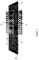
- FIG. 7 shows the same sensor configuration as FIG. 6 , except that member 31 is shown as an additional part of linear movable member 29 .
- FIG. 8 shows the same circuit as in FIG. 1 , with the addition of an oscillator comprising schmitt trigger 34 , capacitor 32 , and resistor 33 .
- Resistor 35 connects to the oscillator of schmitt trigger 2 in a way to add variation to the schmitt trigger 2 oscillation frequency.
- FIG. 9 shows examples of other shapes for the movable member of a position sensor according to the present invention.
- the arc shape of shaped rotary movable member 36 is suited to use in a rotary sensor for changing the rotation angle vs. output function, likewise, the sloped shape of shaped linear movable member 37 is suited to similar use in a linear sensor.
- FIG. 10 shows an example of a sensor configuration, according to the present invention, that measures motion along a nonlinear motion axis 44 .
- First conductor coil 38 is connected in series with second conductor coil 39 , with the interconnection point being brought out on pin 42 . The remaining coil connections are brought out on pins 40 and 41 .
- Movable member 43 follows the nonlinear motion axis 44 .
- FIG. 3 A first preferred embodiment of the present invention is shown in FIG. 3 , and enables the measurement of rotary motion with the minimum of complexity in both the sensor and the associated electronic circuit. Together with the circuit of FIG. 1 , a complete transducer can be constructed with a bare minimum of components, thus providing a simple and inexpensive transducer.
- the movable member is fabricated from a ferromagnetic material, such as a nickel-iron alloy. Alternatively, it can be fabricated from an electrically conductive non-magnetic material, such as aluminum.
- the coil impedance changes with position of the movable member due to the permeability of the ferromagnetic material, since the inductance and therefore the impedance of a coil varies approximately in direct proportion with magnetic permeability.
- the coil impedance changes due to eddy currents that flow in the movable member from electromagnetic induction.
- the production of eddy currents is more effective at higher frequencies, so operating frequencies of 100 kHz or more are preferred when operating in this mode.
- a first impedance 5 , of coil 11 is at a maximum
- a second impedance 6 , of coil 12 is at a minimum.
- the output at pin 9 is at its minimum voltage.
- the output at pin 9 is at its maximum voltage.
- a rotary position sensor according to the present invention must use a coil shape covering 180 degrees of rotation. Coils of other angular dimension can be used. For example, a coil size in which each coil covers a rotation angle of 90 degrees, instead of the 180 degrees of FIG. 3 , can be used.
- a rotary sensor is formed as in FIG. 3 , with the addition to rotary movable member 17 of a second part, 22 . Disposing the two parts of the movable member so that the first part, 17 , is above stationary member 13 , and the second part, 22 , is below rotary stationary member 13 , yield an improved performance over the single part movable member shown in FIG. 3 .
- the improvement is that the output at pin 9 of the circuit of FIG. 1 remains relatively unchanged when the shaft 18 is allowed to move up and down or to wobble.
- any movement of movable member first part, 17 , toward or away from rotary stationary member 13 is compensated by a corresponding movement of movable member second part 22 away or toward, respectively, rotary stationary member 13 .
- temperature-induced changes in the impedance of coils in rotary stationary member 13 are compensated due to a similar effect being introduced into each coil.
- FIG. 7 A third preferred embodiment is shown in FIG. 7 , in which a linear position sensor is formed by the movement of linear movable member 29 , and its second part, member 31 , along motion axis 30 .
- a linear position sensor is formed by the movement of linear movable member 29 , and its second part, member 31 , along motion axis 30 .
- the circuit of FIG. 8 can be used instead of that in FIG. 1 .
- the output of oscillator 32 , 33 , 34 (called the control oscillator) is connected to oscillator 1 , 2 , 3 (called the drive oscillator) through resistor 35 .
- the drive oscillator drives the sensing element at a frequency, for example 1 MHz.
- the control oscillator causes a relatively small variation in the frequency of the drive oscillator, typically on the order of two percent, or less, of the drive frequency; for example, a variation of 10 KHz. This percentage is adjusted through the resistance value of resistor 35 .
- the frequency of the control oscillator is typically on the order of less than one percent of the frequency of the drive oscillator, for example 1 KHz.
- the reciprocal of this frequency is the scan rate, and is adjusted through the value of resistor 33 or capacitor 32 . So, in the example, the frequency of the 1 MHz drive oscillator will vary by 20 KHz at a scan rate of 1 KHz. The advantage of this is to reduce the concentration of energy into any one frequency, thus making it easier to remain within the requirements of standards for limiting electromagnetic radiation.
- a control signal from another source can be used to vary the frequency of the drive oscillator.
- Shapes such as movable members 36 and 37 serve to modify the output function vs. measurand in two ways.
- the first way is to extend the measurement range for a given coil size.
- a movable member shape as in 37 to replace 29 in FIG. 6
- the length of motion axis 30 can be increased.
- the inductance of both coils may be increasing at the same time, but one increases faster than the other. So, this function still results in a monotonic output on pin 9 in the circuit of FIG. 1 .
- the second way in which the sensor output function can be modified by shaping the movable member is to change the shape of the transfer function of output vs. measurand.
- the movable member 36 can be used instead of the movable member 17 of FIG. 3 , with a given set of coils 11 and 12 .
- the transfer function of sensor output vs. movement along the motion axis will change and this can be used to tailor the sensor transfer function as desired, for example: in the reduction of nonlinearity error.
- the present invention also teaches the use of similar movable and stationary member configurations to implement sensors with a nonlinear motion axis shape.
- An example is shown in FIG. 10 .
- Coils 38 and 39 are shaped to conform to the desired nonlinear motion axis 44 .
- the coils are connected to a circuit such as that of FIG. 1 .
- the output at pin 9 of the circuit of FIG. 1 changes in response to the movement.
- FIGS. 2 through 7 and FIG. 10 show the inductor coils each as a single conductor pattern layer on the top of a flat dielectric material substrate, such as a printed circuit board.
- a printed circuit board can be fabricated as having one or more layers of a conductor pattern in addition to the initial layer.
- additional layers are used in accordance with the present invention for the purpose of increasing the inductance of a sensing coil for a given surface area, and thus the impedance of that coil at a given frequency of operation.
- coils 11 and 12 can be fabricated in a four layer printed circuit board, with each additional conductor layer positioned below the previous layer of the respective coil.
- Coil 11 would have four layers and coil 12 would have four layers, all included within one simple printed circuit board according to popular manufacturing methods well known in the art. According to the present invention, the two resulting coils would be connected together in series and form impedances as in 5 and 6 of FIG. 1 .
Abstract
Description
Claims (14)
Priority Applications (1)
| Application Number | Priority Date | Filing Date | Title |
|---|---|---|---|
| US10/847,500 US7135855B2 (en) | 2004-05-17 | 2004-05-17 | Simplified inductive position sensor and circuit configuration |
Applications Claiming Priority (1)
| Application Number | Priority Date | Filing Date | Title |
|---|---|---|---|
| US10/847,500 US7135855B2 (en) | 2004-05-17 | 2004-05-17 | Simplified inductive position sensor and circuit configuration |
Publications (2)
| Publication Number | Publication Date |
|---|---|
| US20050253576A1 US20050253576A1 (en) | 2005-11-17 |
| US7135855B2 true US7135855B2 (en) | 2006-11-14 |
Family
ID=35308812
Family Applications (1)
| Application Number | Title | Priority Date | Filing Date |
|---|---|---|---|
| US10/847,500 Active - Reinstated 2024-09-11 US7135855B2 (en) | 2004-05-17 | 2004-05-17 | Simplified inductive position sensor and circuit configuration |
Country Status (1)
| Country | Link |
|---|---|
| US (1) | US7135855B2 (en) |
Cited By (19)
| Publication number | Priority date | Publication date | Assignee | Title |
|---|---|---|---|---|
| US20090033316A1 (en) * | 2007-06-27 | 2009-02-05 | Brooks Automation, Inc. | Sensor for position and gap measurement |
| KR101023198B1 (en) * | 2008-06-30 | 2011-03-18 | 주식회사 트루윈 | Inductive Displacement Sensor and Receiving Coil Structure and Signal Processing Method for Gap Compensation of The Same |
| US8283813B2 (en) | 2007-06-27 | 2012-10-09 | Brooks Automation, Inc. | Robot drive with magnetic spindle bearings |
| US20140002069A1 (en) * | 2012-06-27 | 2014-01-02 | Kenneth Stoddard | Eddy current probe |
| US8659205B2 (en) | 2007-06-27 | 2014-02-25 | Brooks Automation, Inc. | Motor stator with lift capability and reduced cogging characteristics |
| US8680803B2 (en) | 2007-07-17 | 2014-03-25 | Brooks Automation, Inc. | Substrate processing apparatus with motors integral to chamber walls |
| US8742715B2 (en) | 2011-06-09 | 2014-06-03 | Simmonds Precision Products, Inc. | System and method for providing control of an electric motor using inductive rotary sensor |
| US8803513B2 (en) | 2007-06-27 | 2014-08-12 | Brooks Automation, Inc. | Multiple dimension position sensor |
| US8823294B2 (en) | 2007-06-27 | 2014-09-02 | Brooks Automation, Inc. | Commutation of an electromagnetic propulsion and guidance system |
| CN105241373A (en) * | 2014-05-08 | 2016-01-13 | 罗伯特·博世有限公司 | Sensor arrangement for sensing rotation angles on a rotating component in a vehicle |
| CN106124365A (en) * | 2016-08-26 | 2016-11-16 | 李玉峰 | Intelligent blood stagnates condition checkout gear and method |
| CN106153503A (en) * | 2016-08-26 | 2016-11-23 | 李玉峰 | A kind of blood profile system for accurate medical treatment detection and method |
| CN106153504A (en) * | 2016-08-26 | 2016-11-23 | 李玉峰 | Blood testing equipment and method |
| CN106198317A (en) * | 2016-08-26 | 2016-12-07 | 李玉峰 | Blood stagnation condition checkout gear and method for precisely medical treatment detection |
| CN106198318A (en) * | 2016-08-26 | 2016-12-07 | 李玉峰 | A kind of Intelligent blood test system and method |
| CN106353221A (en) * | 2016-08-26 | 2017-01-25 | 李玉峰 | Blood stagnation state detection equipment and blood stagnation state detection method |
| US9752615B2 (en) | 2007-06-27 | 2017-09-05 | Brooks Automation, Inc. | Reduced-complexity self-bearing brushless DC motor |
| US11002566B2 (en) | 2007-06-27 | 2021-05-11 | Brooks Automation, Inc. | Position feedback for self bearing motor |
| US11353338B2 (en) * | 2017-08-21 | 2022-06-07 | KSR IP Holdings, LLC | Inductive sensor module assembly with a center signal processor |
Families Citing this family (33)
| Publication number | Priority date | Publication date | Assignee | Title |
|---|---|---|---|---|
| US8104810B2 (en) * | 2006-11-01 | 2012-01-31 | Norgren Automotive Solutions, Inc. | Gripper having sensor for detecting displacement |
| DE102006062031B3 (en) * | 2006-12-29 | 2008-06-19 | Advanced Micro Devices, Inc., Sunnyvale | Electrochemical etching assembly has drive unit in frame above electrochemical vat |
| DE102007011952B4 (en) * | 2007-03-09 | 2019-09-26 | Werner Turck Gmbh & Co. Kg | Motion measuring device, in particular rotary encoder |
| US20080284554A1 (en) * | 2007-05-14 | 2008-11-20 | Thaddeus Schroeder | Compact robust linear position sensor |
| US20090309578A1 (en) * | 2008-06-16 | 2009-12-17 | Cochran William T | Sensor inductors, sensors for monitoring movements and positioning, apparatus, systems and methods therefore |
| US8405386B2 (en) * | 2009-02-17 | 2013-03-26 | Goodrich Corporation | Non-contact sensor system and method for position determination |
| US8164326B2 (en) * | 2009-02-17 | 2012-04-24 | Goodrich Corporation | Non-contact sensor system and method for velocity determination |
| US8203331B2 (en) * | 2009-02-17 | 2012-06-19 | Goodrich Corporation | Non-contact sensor system and method for selection determination |
| US8207729B2 (en) * | 2009-02-17 | 2012-06-26 | Goodrich Corporation | Non-contact sensor system and method for displacement determination |
| US8919844B1 (en) | 2012-05-18 | 2014-12-30 | Norgren Automation Solutions, Llc | Gripper with actuator mounted displacement sensor |
| US9052219B2 (en) * | 2012-11-06 | 2015-06-09 | Continental Automotive Systems, Inc. | Inductive position sensor with field shaping elements |
| US20140169987A1 (en) * | 2012-12-13 | 2014-06-19 | Caterpillar Inc. | Dielectric Sensor Arrangement and Method for Swashplate Angular Position Detection |
| US10856452B1 (en) * | 2013-03-14 | 2020-12-01 | David Fiori, Jr. | Sensor apparatus |
| DE102014212319A1 (en) | 2014-06-26 | 2015-12-31 | Schaeffler Technologies AG & Co. KG | Camshaft adjuster and method for determining the adjustment of a camshaft adjuster |
| DE102014220458A1 (en) * | 2014-10-09 | 2016-04-14 | Robert Bosch Gmbh | Sensor arrangement for the contactless detection of angles of rotation on a rotating component |
| DE102014220446A1 (en) | 2014-10-09 | 2016-04-14 | Robert Bosch Gmbh | Sensor arrangement for the contactless detection of angles of rotation on a rotating component |
| CN104567651A (en) * | 2014-12-16 | 2015-04-29 | 中国科学院苏州生物医学工程技术研究所 | PCB planar differential inductive angular displacement sensor |
| DE102015200620A1 (en) | 2015-01-16 | 2016-07-21 | Zf Friedrichshafen Ag | Inductive position determination |
| DE102015222017A1 (en) | 2015-09-15 | 2017-03-16 | Micro-Epsilon Messtechnik Gmbh & Co. Kg | Device and sensor for contactless distance and / or position determination of a measurement object |
| US10408642B2 (en) * | 2016-11-02 | 2019-09-10 | Ksr Ip Holdings Llc | Duty cycle modulation for inductive position sensors |
| DE112017006526B4 (en) * | 2017-01-27 | 2021-01-14 | Mitsubishi Electric Corporation | Electromagnetic field probe |
| WO2019089073A1 (en) | 2017-11-02 | 2019-05-09 | Ksr Ip Holdings Llc. | Duty cycle for inductive position sensors |
| US11047710B2 (en) * | 2018-05-23 | 2021-06-29 | KSR IP Holdings, LLC | Inductive position sensor assembly |
| US10914570B2 (en) * | 2018-11-01 | 2021-02-09 | Mitutoyo Corporation | Inductive position detection configuration for indicating a measurement device stylus position |
| US11740064B2 (en) | 2018-11-01 | 2023-08-29 | Mitutoyo Corporation | Inductive position detection configuration for indicating a measurement device stylus position |
| US11543899B2 (en) | 2018-11-01 | 2023-01-03 | Mitutoyo Corporation | Inductive position detection configuration for indicating a measurement device stylus position and including coil misalignment compensation |
| US11644298B2 (en) | 2018-11-01 | 2023-05-09 | Mitutoyo Corporation | Inductive position detection configuration for indicating a measurement device stylus position |
| US10760928B1 (en) | 2019-02-21 | 2020-09-01 | Microsemi Corporation | Planar linear inductive position sensor having edge effect compensation |
| US11644299B2 (en) | 2020-12-31 | 2023-05-09 | Mitutoyo Corporation | Inductive position sensor signal gain control for coordinate measuring machine probe |
| WO2023037154A1 (en) * | 2021-09-10 | 2023-03-16 | Bosch Car Multimedia Portugal, S.A. | Rotational sensor |
| US11733021B2 (en) | 2021-12-22 | 2023-08-22 | Mitutoyo Corporation | Modular configuration for coordinate measuring machine probe |
| US11713956B2 (en) | 2021-12-22 | 2023-08-01 | Mitutoyo Corporation | Shielding for sensor configuration and alignment of coordinate measuring machine probe |
| CN117470281B (en) * | 2023-12-27 | 2024-04-09 | 峰岹科技(深圳)股份有限公司 | Electromagnetic structure for angle sensor and angle sensor |
Citations (20)
| Publication number | Priority date | Publication date | Assignee | Title |
|---|---|---|---|---|
| US2341346A (en) * | 1942-02-20 | 1944-02-08 | Gen Electric | High frequency coupling circuit |
| US4613843A (en) * | 1984-10-22 | 1986-09-23 | Ford Motor Company | Planar coil magnetic transducer |
| US4663589A (en) * | 1985-02-11 | 1987-05-05 | Sensor Technologies, Inc. | Displacement sensor having multiplexed dual tank circuits |
| US4777436A (en) * | 1985-02-11 | 1988-10-11 | Sensor Technologies, Inc. | Inductance coil sensor |
| US4851770A (en) * | 1985-02-11 | 1989-07-25 | Sensor Technologies, Inc. | Displacement sensor having dual tank circuits |
| US5079523A (en) * | 1990-03-15 | 1992-01-07 | Robert Bosch Gmbh | Inductive position indicator using two oscillators with periodically interchanged inductors |
| US5175497A (en) * | 1990-01-20 | 1992-12-29 | Robert Bosch Gmbh | Measuring device for determination of rotary angle |
| US5204621A (en) * | 1990-02-08 | 1993-04-20 | Papst-Motoren Gmbh & Co. Kg | Position sensor employing a soft magnetic core |
| US5248938A (en) * | 1991-05-24 | 1993-09-28 | Asmo Co., Ltd. | Inductance type rotational position sensor including a magnetic core having fixed and movable short rings |
| US5402096A (en) * | 1992-03-27 | 1995-03-28 | Penny & Giles Position Sensors Limited | Transducers |
| US5475302A (en) * | 1991-08-16 | 1995-12-12 | Walter Mehnert | Inductive pick-up for producing a signal representing the relative positions of two mutually movable bodies |
| US5682097A (en) * | 1996-01-31 | 1997-10-28 | Eastman Kodak Company | Electromagnetic actuator with movable coil and position sensor for drive coil |
| US20010052771A1 (en) * | 2000-05-24 | 2001-12-20 | Balluff Gmbh | Position measuring system |
| US6348791B2 (en) * | 1994-07-22 | 2002-02-19 | Genghiscomm, L.L.C. | Method and apparatus for a full-duplex electromagnetic transceiver |
| US6483295B2 (en) * | 2000-05-25 | 2002-11-19 | Hella Kg Hueck & Co. | Inductive linear position sensor including exciting and receiving coils and a movable induction coupling element |
| US6541960B2 (en) * | 2000-03-29 | 2003-04-01 | Sony Precision Technology Inc. | Position detector utilizing magnetic sensors and a bias magnetic field generator |
| US6605939B1 (en) * | 1999-09-08 | 2003-08-12 | Siemens Vdo Automotive Corporation | Inductive magnetic saturation displacement sensor |
| US20030151402A1 (en) * | 2000-06-26 | 2003-08-14 | Ulrich Kindler | Device for contactless measurement of a displacement path, especially for the detection of position and movement |
| US6642710B2 (en) * | 1999-04-23 | 2003-11-04 | Scientific Generics Limited | Position sensor |
| US6756779B2 (en) * | 2000-05-08 | 2004-06-29 | Horst Siedle Gmbh & Co. Kg | Inductive measuring transducer for determining the relative position of a body |
Family Cites Families (1)
| Publication number | Priority date | Publication date | Assignee | Title |
|---|---|---|---|---|
| US4644570A (en) * | 1985-09-20 | 1987-02-17 | Bitronics, Inc. | Sensor amplification and enhancement apparatus using digital techniques |
-
2004
- 2004-05-17 US US10/847,500 patent/US7135855B2/en active Active - Reinstated
Patent Citations (20)
| Publication number | Priority date | Publication date | Assignee | Title |
|---|---|---|---|---|
| US2341346A (en) * | 1942-02-20 | 1944-02-08 | Gen Electric | High frequency coupling circuit |
| US4613843A (en) * | 1984-10-22 | 1986-09-23 | Ford Motor Company | Planar coil magnetic transducer |
| US4663589A (en) * | 1985-02-11 | 1987-05-05 | Sensor Technologies, Inc. | Displacement sensor having multiplexed dual tank circuits |
| US4777436A (en) * | 1985-02-11 | 1988-10-11 | Sensor Technologies, Inc. | Inductance coil sensor |
| US4851770A (en) * | 1985-02-11 | 1989-07-25 | Sensor Technologies, Inc. | Displacement sensor having dual tank circuits |
| US5175497A (en) * | 1990-01-20 | 1992-12-29 | Robert Bosch Gmbh | Measuring device for determination of rotary angle |
| US5204621A (en) * | 1990-02-08 | 1993-04-20 | Papst-Motoren Gmbh & Co. Kg | Position sensor employing a soft magnetic core |
| US5079523A (en) * | 1990-03-15 | 1992-01-07 | Robert Bosch Gmbh | Inductive position indicator using two oscillators with periodically interchanged inductors |
| US5248938A (en) * | 1991-05-24 | 1993-09-28 | Asmo Co., Ltd. | Inductance type rotational position sensor including a magnetic core having fixed and movable short rings |
| US5475302A (en) * | 1991-08-16 | 1995-12-12 | Walter Mehnert | Inductive pick-up for producing a signal representing the relative positions of two mutually movable bodies |
| US5402096A (en) * | 1992-03-27 | 1995-03-28 | Penny & Giles Position Sensors Limited | Transducers |
| US6348791B2 (en) * | 1994-07-22 | 2002-02-19 | Genghiscomm, L.L.C. | Method and apparatus for a full-duplex electromagnetic transceiver |
| US5682097A (en) * | 1996-01-31 | 1997-10-28 | Eastman Kodak Company | Electromagnetic actuator with movable coil and position sensor for drive coil |
| US6642710B2 (en) * | 1999-04-23 | 2003-11-04 | Scientific Generics Limited | Position sensor |
| US6605939B1 (en) * | 1999-09-08 | 2003-08-12 | Siemens Vdo Automotive Corporation | Inductive magnetic saturation displacement sensor |
| US6541960B2 (en) * | 2000-03-29 | 2003-04-01 | Sony Precision Technology Inc. | Position detector utilizing magnetic sensors and a bias magnetic field generator |
| US6756779B2 (en) * | 2000-05-08 | 2004-06-29 | Horst Siedle Gmbh & Co. Kg | Inductive measuring transducer for determining the relative position of a body |
| US20010052771A1 (en) * | 2000-05-24 | 2001-12-20 | Balluff Gmbh | Position measuring system |
| US6483295B2 (en) * | 2000-05-25 | 2002-11-19 | Hella Kg Hueck & Co. | Inductive linear position sensor including exciting and receiving coils and a movable induction coupling element |
| US20030151402A1 (en) * | 2000-06-26 | 2003-08-14 | Ulrich Kindler | Device for contactless measurement of a displacement path, especially for the detection of position and movement |
Cited By (21)
| Publication number | Priority date | Publication date | Assignee | Title |
|---|---|---|---|---|
| US9024488B2 (en) | 2007-06-27 | 2015-05-05 | Brooks Automation, Inc. | Robot drive with magnetic spindle bearings |
| US8283813B2 (en) | 2007-06-27 | 2012-10-09 | Brooks Automation, Inc. | Robot drive with magnetic spindle bearings |
| US20090033316A1 (en) * | 2007-06-27 | 2009-02-05 | Brooks Automation, Inc. | Sensor for position and gap measurement |
| US11002566B2 (en) | 2007-06-27 | 2021-05-11 | Brooks Automation, Inc. | Position feedback for self bearing motor |
| US9752615B2 (en) | 2007-06-27 | 2017-09-05 | Brooks Automation, Inc. | Reduced-complexity self-bearing brushless DC motor |
| US8659205B2 (en) | 2007-06-27 | 2014-02-25 | Brooks Automation, Inc. | Motor stator with lift capability and reduced cogging characteristics |
| US8803513B2 (en) | 2007-06-27 | 2014-08-12 | Brooks Automation, Inc. | Multiple dimension position sensor |
| US8823294B2 (en) | 2007-06-27 | 2014-09-02 | Brooks Automation, Inc. | Commutation of an electromagnetic propulsion and guidance system |
| US8222892B2 (en) | 2007-06-27 | 2012-07-17 | Brooks Automation, Inc. | Sensor for simultaneous position and gap measurement |
| US8680803B2 (en) | 2007-07-17 | 2014-03-25 | Brooks Automation, Inc. | Substrate processing apparatus with motors integral to chamber walls |
| KR101023198B1 (en) * | 2008-06-30 | 2011-03-18 | 주식회사 트루윈 | Inductive Displacement Sensor and Receiving Coil Structure and Signal Processing Method for Gap Compensation of The Same |
| US8742715B2 (en) | 2011-06-09 | 2014-06-03 | Simmonds Precision Products, Inc. | System and method for providing control of an electric motor using inductive rotary sensor |
| US20140002069A1 (en) * | 2012-06-27 | 2014-01-02 | Kenneth Stoddard | Eddy current probe |
| CN105241373A (en) * | 2014-05-08 | 2016-01-13 | 罗伯特·博世有限公司 | Sensor arrangement for sensing rotation angles on a rotating component in a vehicle |
| CN106153503A (en) * | 2016-08-26 | 2016-11-23 | 李玉峰 | A kind of blood profile system for accurate medical treatment detection and method |
| CN106153504A (en) * | 2016-08-26 | 2016-11-23 | 李玉峰 | Blood testing equipment and method |
| CN106198317A (en) * | 2016-08-26 | 2016-12-07 | 李玉峰 | Blood stagnation condition checkout gear and method for precisely medical treatment detection |
| CN106198318A (en) * | 2016-08-26 | 2016-12-07 | 李玉峰 | A kind of Intelligent blood test system and method |
| CN106353221A (en) * | 2016-08-26 | 2017-01-25 | 李玉峰 | Blood stagnation state detection equipment and blood stagnation state detection method |
| CN106124365A (en) * | 2016-08-26 | 2016-11-16 | 李玉峰 | Intelligent blood stagnates condition checkout gear and method |
| US11353338B2 (en) * | 2017-08-21 | 2022-06-07 | KSR IP Holdings, LLC | Inductive sensor module assembly with a center signal processor |
Also Published As
| Publication number | Publication date |
|---|---|
| US20050253576A1 (en) | 2005-11-17 |
Similar Documents
| Publication | Publication Date | Title |
|---|---|---|
| US7135855B2 (en) | Simplified inductive position sensor and circuit configuration | |
| US10036656B2 (en) | Position detecting system based on inductive sensing | |
| Fericean et al. | New noncontacting inductive analog proximity and inductive linear displacement sensors for industrial automation | |
| JP4662539B2 (en) | Multi-directional distance non-contact measuring instrument | |
| KR101313121B1 (en) | Linear and rotational inductive position sensor | |
| US6124708A (en) | Position detection using a spaced apart array of magnetic field generators and plural sensing loop circuits offset from one another in the measurement direction | |
| US10760928B1 (en) | Planar linear inductive position sensor having edge effect compensation | |
| CN110657826B (en) | Scale structure for inductive position encoder | |
| EP1875172B1 (en) | Eddy-current sensor for magnetic bearing device | |
| JP5047833B2 (en) | Displacement sensor system and displacement sensor | |
| US9927261B1 (en) | Inductive sensor device for use with a distance measurement device | |
| Reddy et al. | Low cost planar coil structure for inductive sensors to measure absolute angular position | |
| US6922051B2 (en) | Displacement and/or angle sensor with a meander-shaped measuring winding | |
| EP3514559B1 (en) | Sensor package | |
| CN112857194A (en) | Plane two-dimensional displacement sensor based on eddy current effect | |
| CN107430207A (en) | Position sensor | |
| KR20180108642A (en) | sensor | |
| EP4009004A1 (en) | Eddy current sensor device for measuring a linear displacement | |
| US11703359B2 (en) | Inductive position sensing apparatus including a screening layer and method for the same | |
| EP4053509A1 (en) | Target and receiver for an inductive sensor | |
| JPH11173872A (en) | Linear resolver signal generating method, and linear resolver | |
| CN114689092A (en) | Sensing winding configuration for inductive position encoder | |
| CN113758408A (en) | Position sensor with varying output slope | |
| JP2005201855A (en) | Induction displacement detection device and micrometer |
Legal Events
| Date | Code | Title | Description |
|---|---|---|---|
| FEPP | Fee payment procedure |
Free format text: PETITION RELATED TO MAINTENANCE FEES FILED (ORIGINAL EVENT CODE: PMFP); ENTITY STATUS OF PATENT OWNER: SMALL ENTITY Free format text: PETITION RELATED TO MAINTENANCE FEES GRANTED (ORIGINAL EVENT CODE: PMFG); ENTITY STATUS OF PATENT OWNER: SMALL ENTITY |
|
| REMI | Maintenance fee reminder mailed | ||
| REIN | Reinstatement after maintenance fee payment confirmed | ||
| PRDP | Patent reinstated due to the acceptance of a late maintenance fee |
Effective date: 20101223 |
|
| FPAY | Fee payment |
Year of fee payment: 4 |
|
| STCF | Information on status: patent grant |
Free format text: PATENTED CASE |
|
| SULP | Surcharge for late payment | ||
| FP | Lapsed due to failure to pay maintenance fee |
Effective date: 20101114 |
|
| FPAY | Fee payment |
Year of fee payment: 8 |
|
| MAFP | Maintenance fee payment |
Free format text: PAYMENT OF MAINTENANCE FEE, 12TH YR, SMALL ENTITY (ORIGINAL EVENT CODE: M2553) Year of fee payment: 12 |