US7115199B2 - Filter housing with interchangeable filter mounting plate - Google Patents
Filter housing with interchangeable filter mounting plate Download PDFInfo
- Publication number
- US7115199B2 US7115199B2 US10/903,997 US90399704A US7115199B2 US 7115199 B2 US7115199 B2 US 7115199B2 US 90399704 A US90399704 A US 90399704A US 7115199 B2 US7115199 B2 US 7115199B2
- Authority
- US
- United States
- Prior art keywords
- housing
- mounting plate
- housing member
- fluid
- fluid treatment
- Prior art date
- Legal status (The legal status is an assumption and is not a legal conclusion. Google has not performed a legal analysis and makes no representation as to the accuracy of the status listed.)
- Expired - Fee Related, expires
Links
Images


Classifications
-
- B—PERFORMING OPERATIONS; TRANSPORTING
- B01—PHYSICAL OR CHEMICAL PROCESSES OR APPARATUS IN GENERAL
- B01D—SEPARATION
- B01D35/00—Filtering devices having features not specifically covered by groups B01D24/00 - B01D33/00, or for applications not specifically covered by groups B01D24/00 - B01D33/00; Auxiliary devices for filtration; Filter housing constructions
- B01D35/30—Filter housing constructions
-
- B—PERFORMING OPERATIONS; TRANSPORTING
- B01—PHYSICAL OR CHEMICAL PROCESSES OR APPARATUS IN GENERAL
- B01D—SEPARATION
- B01D29/00—Filters with filtering elements stationary during filtration, e.g. pressure or suction filters, not covered by groups B01D24/00 - B01D27/00; Filtering elements therefor
- B01D29/11—Filters with filtering elements stationary during filtration, e.g. pressure or suction filters, not covered by groups B01D24/00 - B01D27/00; Filtering elements therefor with bag, cage, hose, tube, sleeve or like filtering elements
- B01D29/114—Filters with filtering elements stationary during filtration, e.g. pressure or suction filters, not covered by groups B01D24/00 - B01D27/00; Filtering elements therefor with bag, cage, hose, tube, sleeve or like filtering elements arranged for inward flow filtration
-
- B—PERFORMING OPERATIONS; TRANSPORTING
- B01—PHYSICAL OR CHEMICAL PROCESSES OR APPARATUS IN GENERAL
- B01D—SEPARATION
- B01D29/00—Filters with filtering elements stationary during filtration, e.g. pressure or suction filters, not covered by groups B01D24/00 - B01D27/00; Filtering elements therefor
- B01D29/11—Filters with filtering elements stationary during filtration, e.g. pressure or suction filters, not covered by groups B01D24/00 - B01D27/00; Filtering elements therefor with bag, cage, hose, tube, sleeve or like filtering elements
- B01D29/117—Filters with filtering elements stationary during filtration, e.g. pressure or suction filters, not covered by groups B01D24/00 - B01D27/00; Filtering elements therefor with bag, cage, hose, tube, sleeve or like filtering elements arranged for outward flow filtration
-
- B—PERFORMING OPERATIONS; TRANSPORTING
- B01—PHYSICAL OR CHEMICAL PROCESSES OR APPARATUS IN GENERAL
- B01D—SEPARATION
- B01D29/00—Filters with filtering elements stationary during filtration, e.g. pressure or suction filters, not covered by groups B01D24/00 - B01D27/00; Filtering elements therefor
- B01D29/50—Filters with filtering elements stationary during filtration, e.g. pressure or suction filters, not covered by groups B01D24/00 - B01D27/00; Filtering elements therefor with multiple filtering elements, characterised by their mutual disposition
- B01D29/52—Filters with filtering elements stationary during filtration, e.g. pressure or suction filters, not covered by groups B01D24/00 - B01D27/00; Filtering elements therefor with multiple filtering elements, characterised by their mutual disposition in parallel connection
-
- B—PERFORMING OPERATIONS; TRANSPORTING
- B01—PHYSICAL OR CHEMICAL PROCESSES OR APPARATUS IN GENERAL
- B01D—SEPARATION
- B01D29/00—Filters with filtering elements stationary during filtration, e.g. pressure or suction filters, not covered by groups B01D24/00 - B01D27/00; Filtering elements therefor
- B01D29/50—Filters with filtering elements stationary during filtration, e.g. pressure or suction filters, not covered by groups B01D24/00 - B01D27/00; Filtering elements therefor with multiple filtering elements, characterised by their mutual disposition
- B01D29/56—Filters with filtering elements stationary during filtration, e.g. pressure or suction filters, not covered by groups B01D24/00 - B01D27/00; Filtering elements therefor with multiple filtering elements, characterised by their mutual disposition in series connection
- B01D29/58—Filters with filtering elements stationary during filtration, e.g. pressure or suction filters, not covered by groups B01D24/00 - B01D27/00; Filtering elements therefor with multiple filtering elements, characterised by their mutual disposition in series connection arranged concentrically or coaxially
-
- B—PERFORMING OPERATIONS; TRANSPORTING
- B01—PHYSICAL OR CHEMICAL PROCESSES OR APPARATUS IN GENERAL
- B01D—SEPARATION
- B01D29/00—Filters with filtering elements stationary during filtration, e.g. pressure or suction filters, not covered by groups B01D24/00 - B01D27/00; Filtering elements therefor
- B01D29/96—Filters with filtering elements stationary during filtration, e.g. pressure or suction filters, not covered by groups B01D24/00 - B01D27/00; Filtering elements therefor in which the filtering elements are moved between filtering operations; Particular measures for removing or replacing the filtering elements; Transport systems for filters
-
- B—PERFORMING OPERATIONS; TRANSPORTING
- B01—PHYSICAL OR CHEMICAL PROCESSES OR APPARATUS IN GENERAL
- B01D—SEPARATION
- B01D2201/00—Details relating to filtering apparatus
- B01D2201/04—Supports for the filtering elements
- B01D2201/043—Filter tubes connected to plates
- B01D2201/0438—Filter tubes connected to plates mounted substantially vertically on plates at the lower side of the filter elements
-
- B—PERFORMING OPERATIONS; TRANSPORTING
- B01—PHYSICAL OR CHEMICAL PROCESSES OR APPARATUS IN GENERAL
- B01D—SEPARATION
- B01D2201/00—Details relating to filtering apparatus
- B01D2201/04—Supports for the filtering elements
- B01D2201/043—Filter tubes connected to plates
- B01D2201/0446—Filter tubes connected to plates suspended from plates at the upper side of the filter elements
Definitions
- the present invention relates generally to a fluid treatment apparatus having interchangeable fluid treatment elements. More specifically, it relates to a filter housing that can be adapted to accommodate different filter elements within a housing unit, including accommodating both inside-out and outside-in flow filters in a single housing.
- Filters for removing impurities from fluid are well known and are used in many applications.
- fluid treatment arrangements may be used to remove particulate matter from oil or water.
- filter elements are utilized with a particular size, capacity and fixed number within a fluid treatment arrangement.
- These can include pre and post filter elements or fluid treatment materials such as charcoal or exchange resin materials and the like.
- a fluid filtration housing system comprising a first housing member, a second housing member and at least one interchangeable filter element mounting plate, said mounting plate comprising one or more apertures each having element mounts for releasably receiving a filter element.
- the element mounting plate can be changed to a different mounting plate to accommodate different treatment elements with different flow characteristics, commercially available from a variety of element manufacturers.
- the interchangeable filter element mounting plate preferably has a mounting flange for securing the mounting plate within the housing members.
- the mounting flange is secured between closure flanges on the housing members in a sealed relationship.
- the fluid treatment housing system provides that fluid can be filtered in one direction, whereby the particulate matter is collected on the inside surface of the filter elements and, if desired, the housing system can be easily adapted to filter fluid in the other direction, to collect particulate matter on the outside of filter elements when the fluid direction across the filter is reversed.
- the filter housing of the present invention can be further modified to pre-treat fluid by using a second housing member having an extended height for accommodating an additional set of filter elements.
- a second or post treatment of the fluid traveling in the opposite direction can be obtained within the extended second housing member.
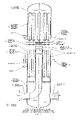
- FIG. 1 is a medial cross-sectional view of a filter housing system in accordance with the present invention, containing an inflow and outflow conduit within the first housing member illustrating inside-out filter elements suspended from the element mounting plate within the first housing member.
- the filter housing system is fitted with inside-out flow filter elements and a housing bonnet.
- FIG. 2 is a medial cross-sectional view of the filter housing system showing the element mounting plate replaced with a basket shaped outside-in filter element flow mounting plate, fitted with outside-in flow filter elements.
- FIG. 3 is a medial cross-sectional view of the filter housing system showing the housing fitted with an extended height bonnet and an element mounting plate containing pre-treatment outside-in filter elements. Also, within the extended height bonnet an inlet flow extension conduit and a seal ring installed above the element mounting plate. An after treatment utilizing outside-in flow filter elements in the first housing member.
- FIG. 4 is a medial cross-sectional view of the filter housing system showing the extended height bonnet second housing member with an inlet flow extension conduit and pre-treatment basket shaped element mounting plate with inside-out filter elements and an after treatment using a basket shaped outside-in filter element flow mounting plate with outside-in flow filter elements in the first housing member.
- FIG. 5 is a medial cross-sectional view of the filter housing system showing the housing with pre-filter and after-filter flow modifications, both first and second member housing elements containing inside-out fluid filter elements.
- FIG. 6 is a medial cross-sectional view of a widened first housing member containing an inflow and out flow conduit, fitted with both inside-out and outside-in flow filter elements and a housing bonnet.
- the filter housing accommodates both pre-treatment inside-out flow and after-treatment outside-in within the first filter housing member.
- FIG. 7 is a medial cross-sectional view of a widened first housing member containing an inflow and out flow conduit, fitted with both pre-treatment and after-treatment inside-out flow filter elements within the first filter housing member.
- FIG. 8A is a perspective view of a mounting plate for use in the present housing system with a plurality of apertures for inside-out flow elements.
- FIG. 8B is a perspective view of a mounting plate for use in the present housing system with a plurality of apertures for outside-in flow elements.
- FIG. 8C is a perspective view of a widened mounting plate for use in the present housing system with apertures for inside-out pretreatment elements.
- FIG. 9A is a cross-sectional view of a basket type element mounting plate for outside-in filter flow in the first housing member.
- FIG. 9B is a cross-sectional view of a basket type element mounting plate for inside-out flow in the second housing member.
- FIG. 9C is a cross-sectional view of a basket type element mounting plate for outside-in flow in a widened first housing member.
- FIG. 9D is a cross-sectional view of a basket type element mounting plate for inside-out flow in a widened first housing member.
- FIG. 10 is a conduit seal retainer.
- FIG. 11A is a perspective view of short extension conduit.
- FIG. 11B is a perspective view of long extension conduit.
- FIG. 12 is a common inside-out flow filter element known in the art.
- FIG. 13 is a common outside-in flow filter element known in the art.
- the present invention comprises a first housing member 2 , a second housing member 4 and a replaceable element mounting plate 6 .
- Filters 3 for removing particulate debris from a fluid flow are placed on the mounting plate 6 within the housing members 2 and 4 , wherein one or more of the housing members 2 and 4 include conduits 21 and 7 to receive fluid flow.
- the first and second housing members 2 and 4 are separated by a sealed, substantially flat element mounting plate 6 having filter elements 3 mounted thereon.
- the filter elements 3 are positioned on the mounting plate 6 within the filter housing 2 to receive and remove particulate material from fluid flow between the conduits 21 and 7 .
- the mounting plate 6 and filter elements 3 make up a sealed environment between the first and second housing members 2 and 4 to ensure filtration of the fluid.
- Filter element 3 illustrates an inside-out flow filter element known in the art.
- the open end of the filter is secured to the aperture of mounting plate 6 (as shown in FIG. 8A ) within the filter housing.
- any known method for securing the filters to the mounting plate may be used such as pressure fittings, tie rods or suitable threading.
- a sealed relationship is formed between the first and second housing members 2 and 4 .
- Fluid flow then exits the interior of the filter elements 3 into the interior of first housing member 2 and proceeds through outlet conduit 7 , where it is discharged from the first housing member 2 .
- the sections corresponding to the interior of the first housing member 2 and the second housing member 4 are sealed from one another by a flat mounting plate 6 and filter elements 3 which are mounted thereon.
- the mounting plate 6 forms a sealed environment through the use of gaskets 5 between the mounting plate 6 and housing members 2 and 4 and a conduit seal retainer 9 (as shown in FIG. 10 ) to seal the conduit 21 as it passes through the mounting plate 6 , and into communication with the second housing member 4 .
- first 2 and second 4 housing members are fixed together.
- any known method for attaching the housing members 2 and 4 includes cooperating first and second housing flanges 13 and 11 , through which one or more bolts 8 are inserted and secured with cooperating nuts 10 to maintain the sealed relationship of the housing.
- the mounting plate 6 a is a basket type (as shown in FIG. 9 a ) for retaining alternative filter elements 3 a (as shown in FIG. 13 ) which utilize an outside-in fluid flow, as previously known in the art.
- the Basket type mounting plate 6 a extends down into first housing member 2 and, when filter elements 3 a are attached to the mounting plate 6 a , a sealed environment between the interiors of the housing members 2 and 4 is created.
- filter elements 3 a illustrate an outside-in filter, as known in the art, capable of filtering fluid as fluid flows from the exterior to the interior of the filter elements. As particulate matter is collected on the exterior of filters 3 a , filtered fluid enters the interior of the first housing member 2 and exits the first housing member 2 through the conduit 7 .
- FIG. 3 provides for a first housing member 2 and an extended second housing member 4 a with inlet conduit extension 21 b (as shown in FIG. 11A ), as well as inlet conduit 21 and outlet conduit 7 in the first housing member 2 to receive and discharge fluid flow.
- Filter elements 3 a are located within the second housing member 4 a on a first substantially flat mounting plate 6 c (as shown in FIG. 8B ) for pretreating the fluid.
- a second set of filters 3 a are mounted on a basket type mounting plate 6 a within housing member 2 for an after treatment, providing two filtering treatments in a single pass.
- housing members 4 a and 2 are separated by a flat mounting plate 6 c and a basket mounting plate 6 a having the appropriate gaskets 5 and conduit seal retainer 9 to seal the interior environments of the housing members 2 and 4 a .
- a set of pretreatment filter elements 3 a are attached to the mounting plate 6 c within the extended second housing member 4 a and an after treatment set of filter elements 3 a are attached to basket type mounting plate 6 a within the first housing member 2 .
- particulate material is removed by filters 3 a in housing member 4 a by passing from the exterior of the filters 3 a to the interior of the filters 3 a .
- the pretreated fluids then pass down into the interior of the first housing member 2 , flowing from the exterior of the filters 3 a to the interior of the filters 3 a and into housing member 2 .
- the twice filtered fluids exit the first filter housing 2 via outlet conduit 7 .
- FIG. 4 provides for a first housing member 2 , and an extended housing member 4 a , wherein the first housing member 2 includes an inlet conduit 21 , an inlet conduit extension 21 a (as shown in FIG. 11B ) and an outlet conduit 7 for exit of the fluid.
- the first and second housing members 2 and 4 a are separated by sealed basket mounting plates 6 a and 6 d each having a set of filter 3 a and 3 respectively mounted thereon.
- pretreatment inside-out filters 3 are mounted on basket type mounting plate 6 d (as shown in FIG. 9B ), located in the second housing member 4 a .
- Post treatment outside-in filters 3 a are attached to element mounting plate 6 a hanging into the first housing member 2 .
- the preferred embodiment shown in FIG. 4 provides for pre and post fluid filter treatment wherein fluid flow is directed through inlet conduit 21 into inlet conduit extension 21 a and up to the interior of housing member 4 a at the top end, above the top of the filters 3 .
- the fluid is filtered from the interior to the exterior of the filter elements 3 and down to the exterior of the filter elements 3 a in the first housing member 2 .
- the fluid filters into the interior of the filters 3 a , collecting in the interior of the first housing member 2 and exiting through outlet conduit 7 .
- the configuration of FIG. 4 provides for inside-out pretreatment upstream in the interior of the second housing member 4 a and outside-in post treatment downstream in the interior of the first housing member 2 .
- fluid flows into inlet conduit 21 of the first housing member 2 , through the inlet conduit extension 21 a and into the interior of the second housing member 4 a above the filters 3 .
- the fluid is filtered by passing from the interior to the exterior of filter elements 3 mounted on basket type filter element mounting plate 6 d (as shown in FIG. 9B ), which extends into the second housing member 4 a .
- the filtered fluid then flows from the exterior of the upper pretreatment filters 3 to the interior of the post treatment filter elements 3 in the first housing member 2 , mounted on mounting plate 6 .
- the twice filtered fluid collects in the interior of the first housing member 2 and exits the first housing member 2 through outlet conduit 7 .
- the housing members 2 and 4 a in the preferred embodiment of FIG. 5 are separated by sealed element mounting plates 6 and basket element mounting plate 6 d , having gaskets 5 between the housing members 2 and 4 a and mounting plates 6 and 6 d , respectively, as well as between the mounting plates 6 and 6 d themselves.
- FIG. 6 depicts a twice filtered fluid flow, having a first pretreatment fluid filtration using inside-out filter elements 3 and a second filtration utilizing outside-in filter flow elements 3 a , the entire filtration occurring within a widened first housing member 2 a .
- Fluid flow is directed through inlet conduit 21 and conduit extension 21 b of the first housing member 2 a , into the interior of widened second housing member 4 b , and passes to the interior of inside-out filter flow elements 3 .
- the pretreated fluid exits filters 3 and enters the interior of outside-in filter flow elements 3 a all within the first housing member 2 a.
- housing members 4 b and 2 a are separated by a widened flat mounting plate 6 e (as shown in FIG. 8C ) and a widened basket mounting plate 6 f (as shown in FIG. 9C ) having the appropriate gaskets 5 and conduit seal retainer 9 to seal the interior environments of the housing members 2 a and 4 b .
- a set of pretreatment filter elements 3 are attached to the mounting plate 6 e within the widened first housing member 2 a and an after treatment set of filter elements 3 a are attached to basket type mounting plate 6 f within the widened first housing member 2 a.
- the housing members 2 a and 4 b in the preferred embodiment of FIG. 6 are separated by sealed element mounting plates 6 e and basket element mounting plate 6 f , having gaskets 5 between the housing members 2 a and 4 b and mounting plates 6 e and 6 f , as well as between the mounting plates 6 e and 6 f themselves.
- FIG. 7 depicts a twice filtered fluid flow, having a first and second fluid filtration utilizing inside-out filter flow elements 3 all within a widened first housing member 2 a .
- fluid flow is directed through inlet conduit 21 and inlet conduit extension 21 b of first housing member 2 a , into the interior of widened second housing member 4 b , fluid then passes to the interior of inside-out filter flow elements 3 mounted on flat element plate 6 e .
- the pretreated fluid flow reverses direction and enters filter elements 3 mounted on basket shaped element adapter plate 6 g (as shown in FIG. 9D ), leaving debris as it exits the filters 3 and enters the interior the first housing member 2 a .
- the fluid flow then exits the first filter housing member 2 a via outlet conduit 7 .
- housing members 4 b and 2 a are separated by a widened flat mounting plate 6 e (as shown in FIG. 8C ) and a widened basket mounting plate 6 g (as shown in FIG. 9D ) having the appropriate gaskets 5 and conduit seal retainer 9 to seal the interior environments of the housing members 2 a and 4 b .
- a set of pretreatment filter elements 3 are attached to the mounting plate 6 e within the widened first housing member 2 a and a post treatment set of filter elements 3 are attached to basket type mounting plate 6 g within the widened first housing member 2 a .
- the flow direction through the filter housing will be reversed.
- the inlet conduit 21 will then become the outlet and the outlet conduit 7 the inlet. Additional nozzles in the shell and bonnet to remove separated fluids may also be provided.
- the advantages of a filtration system in accordance with the present invention is that the filter elements can be integrated and interchanged by the user to more effectively and efficiently meet the demands of changes in service conditions.
- the housing members and mounting plates are preferably interchangeable to provide the maximum possibilities for treatment variation in a single system.
- conventional filter housing systems lack the ability to accommodate treatment elements with different flow characteristics from a variety of element manufacturers.
Landscapes
- Chemical & Material Sciences (AREA)
- Chemical Kinetics & Catalysis (AREA)
- Filtration Of Liquid (AREA)
- Filtering Of Dispersed Particles In Gases (AREA)
Abstract
A fluid treatment housing system for fluid filter elements including a first housing member, a second housing member and an interchangeable mounting plate on which one or more filter elements are mounted. The mounting plate may be a substantially flat plate or a basket type structure to accommodate various inside-out and outside-in filter elements. Additionally, more than one mounting plate may be used in a single system so that the system can include both pre and post fluid treatment.
Description
This application is a divisional application of Ser. No. 10/081,315, filed Feb. 21, 2002, now abandoned.
1. Field of the Invention
The present invention relates generally to a fluid treatment apparatus having interchangeable fluid treatment elements. More specifically, it relates to a filter housing that can be adapted to accommodate different filter elements within a housing unit, including accommodating both inside-out and outside-in flow filters in a single housing.
2. Description of the Related Art
Filters for removing impurities from fluid are well known and are used in many applications. For example, fluid treatment arrangements may be used to remove particulate matter from oil or water. Typically, filter elements are utilized with a particular size, capacity and fixed number within a fluid treatment arrangement.
However, the prior art presents an inherent inflexibility on the part of the filtering system to adapt to different conditions. This may render the treatment system incapable of use for different applications. Also, many fluid treatment arrangements include multiple treatment elements. In many such applications where the number of treatment elements may be quite large the housing is very expensive, especially when fabricated from alloy materials.
Existing filter housings are incapable of adapting to changes in service conditions that may necessitate a change in the direction of fluid to be treated, or the like. Compounding this problem is an inability on the part of present housings to accommodate treatment elements with different flow characteristics from a variety of element manufacturers.
It is therefore an object of the present invention to provide a fluid treatment housing system capable of accommodating a plurality of fluid treatment elements of various dimensions with an inherent ability for the user to accommodate both pre and post treatment of fluids. These can include pre and post filter elements or fluid treatment materials such as charcoal or exchange resin materials and the like.
This and other objectives are achieved by the present invention, directed to a fluid filtration housing system comprising a first housing member, a second housing member and at least one interchangeable filter element mounting plate, said mounting plate comprising one or more apertures each having element mounts for releasably receiving a filter element. The element mounting plate can be changed to a different mounting plate to accommodate different treatment elements with different flow characteristics, commercially available from a variety of element manufacturers.
The interchangeable filter element mounting plate preferably has a mounting flange for securing the mounting plate within the housing members. In its most preferred embodiment, the mounting flange is secured between closure flanges on the housing members in a sealed relationship.
The fluid treatment housing system provides that fluid can be filtered in one direction, whereby the particulate matter is collected on the inside surface of the filter elements and, if desired, the housing system can be easily adapted to filter fluid in the other direction, to collect particulate matter on the outside of filter elements when the fluid direction across the filter is reversed.
The filter housing of the present invention can be further modified to pre-treat fluid by using a second housing member having an extended height for accommodating an additional set of filter elements. Correspondingly, when reverse flow of fluid is desired, a second or post treatment of the fluid traveling in the opposite direction can be obtained within the extended second housing member.
The following drawings, in which like reference characters indicate like parts, are included for illustration of the present invention without limiting the invention in any manner whatsoever, wherein:
In the preferred embodiment, shown in the drawings attached hereto, the present invention comprises a first housing member 2, a second housing member 4 and a replaceable element mounting plate 6. Filters 3 for removing particulate debris from a fluid flow are placed on the mounting plate 6 within the housing members 2 and 4, wherein one or more of the housing members 2 and 4 include conduits 21 and 7 to receive fluid flow.
In a preferred embodiment, shown in FIG. 1 , the first and second housing members 2 and 4 are separated by a sealed, substantially flat element mounting plate 6 having filter elements 3 mounted thereon. The filter elements 3 are positioned on the mounting plate 6 within the filter housing 2 to receive and remove particulate material from fluid flow between the conduits 21 and 7. The mounting plate 6 and filter elements 3 make up a sealed environment between the first and second housing members 2 and 4 to ensure filtration of the fluid.
In the embodiment shown in FIG. 1 , fluid flows into the first housing member 2 through inlet conduit 21, into the interior of the second housing member 4 and down through the interior of filter elements 3, where debris are captured within the filter elements 3. Filter element 3 (as shown in FIG. 12 ) illustrates an inside-out flow filter element known in the art. In the preferred embodiment the open end of the filter is secured to the aperture of mounting plate 6 (as shown in FIG. 8A ) within the filter housing.
Any known method for securing the filters to the mounting plate may be used such as pressure fittings, tie rods or suitable threading. However, once the filter element 3 is secured to the mounting plate 6 by the desired method, a sealed relationship is formed between the first and second housing members 2 and 4.
Fluid flow then exits the interior of the filter elements 3 into the interior of first housing member 2 and proceeds through outlet conduit 7, where it is discharged from the first housing member 2.
The sections corresponding to the interior of the first housing member 2 and the second housing member 4 are sealed from one another by a flat mounting plate 6 and filter elements 3 which are mounted thereon. In this regard, the mounting plate 6 forms a sealed environment through the use of gaskets 5 between the mounting plate 6 and housing members 2 and 4 and a conduit seal retainer 9 (as shown in FIG. 10 ) to seal the conduit 21 as it passes through the mounting plate 6, and into communication with the second housing member 4.
Once the filters 3 are installed on the mounting plate 6 in sealed relation therewith, the first 2 and second 4 housing members are fixed together. Although any known method for attaching the housing members 2 and 4 may be used, a method which has been found to be suitable includes cooperating first and second housing flanges 13 and 11, through which one or more bolts 8 are inserted and secured with cooperating nuts 10 to maintain the sealed relationship of the housing.
In the preferred embodiment shown in FIG. 2 , the mounting plate 6 a is a basket type (as shown in FIG. 9 a) for retaining alternative filter elements 3 a (as shown in FIG. 13 ) which utilize an outside-in fluid flow, as previously known in the art. The Basket type mounting plate 6 a extends down into first housing member 2 and, when filter elements 3 a are attached to the mounting plate 6 a, a sealed environment between the interiors of the housing members 2 and 4 is created.
Here, fluid flows into the first housing member 2 through conduit 21, into the interior of the second housing member 4 and about the exterior of the filter elements 3 a. In the preferred embodiment, filter elements 3 a illustrate an outside-in filter, as known in the art, capable of filtering fluid as fluid flows from the exterior to the interior of the filter elements. As particulate matter is collected on the exterior of filters 3 a, filtered fluid enters the interior of the first housing member 2 and exits the first housing member 2 through the conduit 7.
The embodiment shown in FIG. 3 provides for a first housing member 2 and an extended second housing member 4 a with inlet conduit extension 21 b (as shown in FIG. 11A ), as well as inlet conduit 21 and outlet conduit 7 in the first housing member 2 to receive and discharge fluid flow. Filter elements 3 a are located within the second housing member 4 a on a first substantially flat mounting plate 6 c (as shown in FIG. 8B ) for pretreating the fluid. A second set of filters 3 a are mounted on a basket type mounting plate 6 a within housing member 2 for an after treatment, providing two filtering treatments in a single pass.
In the preferred embodiment of FIG. 3 , housing members 4 a and 2 are separated by a flat mounting plate 6 c and a basket mounting plate 6 a having the appropriate gaskets 5 and conduit seal retainer 9 to seal the interior environments of the housing members 2 and 4 a. A set of pretreatment filter elements 3 a are attached to the mounting plate 6 c within the extended second housing member 4 a and an after treatment set of filter elements 3 a are attached to basket type mounting plate 6 a within the first housing member 2.
As fluid flow from conduit 21 enters the interior of the second housing member 4 a, particulate material is removed by filters 3 a in housing member 4 a by passing from the exterior of the filters 3 a to the interior of the filters 3 a. The pretreated fluids then pass down into the interior of the first housing member 2, flowing from the exterior of the filters 3 a to the interior of the filters 3 a and into housing member 2. The twice filtered fluids exit the first filter housing 2 via outlet conduit 7.
Similarly, the preferred embodiment shown in FIG. 4 provides for a first housing member 2, and an extended housing member 4 a, wherein the first housing member 2 includes an inlet conduit 21, an inlet conduit extension 21 a (as shown in FIG. 11B ) and an outlet conduit 7 for exit of the fluid. The first and second housing members 2 and 4 a are separated by sealed basket mounting plates 6 a and 6 d each having a set of filter 3 a and 3 respectively mounted thereon.
In this embodiment, pretreatment inside-out filters 3 are mounted on basket type mounting plate 6 d (as shown in FIG. 9B ), located in the second housing member 4 a. Post treatment outside-in filters 3 a are attached to element mounting plate 6 a hanging into the first housing member 2.
The preferred embodiment shown in FIG. 4 , provides for pre and post fluid filter treatment wherein fluid flow is directed through inlet conduit 21 into inlet conduit extension 21 a and up to the interior of housing member 4 a at the top end, above the top of the filters 3. The fluid is filtered from the interior to the exterior of the filter elements 3 and down to the exterior of the filter elements 3 a in the first housing member 2. The fluid filters into the interior of the filters 3 a, collecting in the interior of the first housing member 2 and exiting through outlet conduit 7. As such, the configuration of FIG. 4 provides for inside-out pretreatment upstream in the interior of the second housing member 4 a and outside-in post treatment downstream in the interior of the first housing member 2.
In the embodiment shown in FIG. 5 , fluid flows into inlet conduit 21 of the first housing member 2, through the inlet conduit extension 21 a and into the interior of the second housing member 4 a above the filters 3. The fluid is filtered by passing from the interior to the exterior of filter elements 3 mounted on basket type filter element mounting plate 6 d (as shown in FIG. 9B ), which extends into the second housing member 4 a. The filtered fluid then flows from the exterior of the upper pretreatment filters 3 to the interior of the post treatment filter elements 3 in the first housing member 2, mounted on mounting plate 6. The twice filtered fluid collects in the interior of the first housing member 2 and exits the first housing member 2 through outlet conduit 7.
The housing members 2 and 4 a in the preferred embodiment of FIG. 5 are separated by sealed element mounting plates 6 and basket element mounting plate 6 d, having gaskets 5 between the housing members 2 and 4 a and mounting plates 6 and 6 d, respectively, as well as between the mounting plates 6 and 6 d themselves.
The preferred embodiment of FIG. 6 depicts a twice filtered fluid flow, having a first pretreatment fluid filtration using inside-out filter elements 3 and a second filtration utilizing outside-in filter flow elements 3 a, the entire filtration occurring within a widened first housing member 2 a. Fluid flow is directed through inlet conduit 21 and conduit extension 21 b of the first housing member 2 a, into the interior of widened second housing member 4 b, and passes to the interior of inside-out filter flow elements 3. The pretreated fluid exits filters 3 and enters the interior of outside-in filter flow elements 3 a all within the first housing member 2 a.
In the preferred embodiment of FIG. 6 , housing members 4 b and 2 a are separated by a widened flat mounting plate 6 e (as shown in FIG. 8C ) and a widened basket mounting plate 6 f (as shown in FIG. 9C ) having the appropriate gaskets 5 and conduit seal retainer 9 to seal the interior environments of the housing members 2 a and 4 b. A set of pretreatment filter elements 3 are attached to the mounting plate 6 e within the widened first housing member 2 a and an after treatment set of filter elements 3 a are attached to basket type mounting plate 6 f within the widened first housing member 2 a.
The housing members 2 a and 4 b in the preferred embodiment of FIG. 6 are separated by sealed element mounting plates 6 e and basket element mounting plate 6 f, having gaskets 5 between the housing members 2 a and 4 b and mounting plates 6 e and 6 f, as well as between the mounting plates 6 e and 6 f themselves.
The preferred embodiment of FIG. 7 depicts a twice filtered fluid flow, having a first and second fluid filtration utilizing inside-out filter flow elements 3 all within a widened first housing member 2 a. When fluid flow is directed through inlet conduit 21 and inlet conduit extension 21 b of first housing member 2 a, into the interior of widened second housing member 4 b, fluid then passes to the interior of inside-out filter flow elements 3 mounted on flat element plate 6 e. At this point the pretreated fluid flow reverses direction and enters filter elements 3 mounted on basket shaped element adapter plate 6 g (as shown in FIG. 9D ), leaving debris as it exits the filters 3 and enters the interior the first housing member 2 a. The fluid flow then exits the first filter housing member 2 a via outlet conduit 7.
In the preferred embodiment of FIG. 7 , housing members 4 b and 2 a are separated by a widened flat mounting plate 6 e (as shown in FIG. 8C ) and a widened basket mounting plate 6 g (as shown in FIG. 9D ) having the appropriate gaskets 5 and conduit seal retainer 9 to seal the interior environments of the housing members 2 a and 4 b. A set of pretreatment filter elements 3 are attached to the mounting plate 6 e within the widened first housing member 2 a and a post treatment set of filter elements 3 are attached to basket type mounting plate 6 g within the widened first housing member 2 a. The housing members 2 a and 4 b in the preferred embodiment of FIG. 7 are separated by sealed element mounting plates 6 e and basket element mounting plate 6 g, having gaskets 5 between the housing members 2 a and 4 b and mounting plates 6 e and 6 g, as well as between the mounting plates 6 e and 6 g.
In some fluid treatment services, such as phase separation, the flow direction through the filter housing will be reversed. The inlet conduit 21 will then become the outlet and the outlet conduit 7 the inlet. Additional nozzles in the shell and bonnet to remove separated fluids may also be provided.
The advantages of a filtration system in accordance with the present invention is that the filter elements can be integrated and interchanged by the user to more effectively and efficiently meet the demands of changes in service conditions. The housing members and mounting plates are preferably interchangeable to provide the maximum possibilities for treatment variation in a single system. As described above in the background section, conventional filter housing systems lack the ability to accommodate treatment elements with different flow characteristics from a variety of element manufacturers.
The ability of the element mounting plate to be replaceable, to adapt to various filter elements, along with the unique combination of pre and after filter modifications as described in the preferred embodiments, sets the present invention apart from the prior art. Those skilled in the art will recognize that changes can be made from the form and detail without departing from the spirit and scope of the invention and that all such changes are intended to be covered, limited only by the appended claims.
Claims (20)
1. A fluid treatment element housing system comprising a first housing member having a fluid inlet and a fluid outlet, a second housing member and a plurality of reversably interchangeable mounting plates, wherein the interchangeable mounting plates comprise at least a first mounting plate comprising one or more apertures each having a mount for releasably mounting a first type fluid treatment element thereon and a second mounting plate comprising one or more apertures each having a mount for releasably mounting a second type fluid treatment element thereon, and further wherein the fluid inlet and fluid outlet remain unchanged regardless of the mounting plate used.
2. The housing system of claim 1 , wherein the mounting plates with the fluid treatment elements mounted thereon create a sealed environment between the interiors of the first and second housing members.
3. The housing system of claim 1 , wherein said first housing member and said second housing member each comprise a closure flange and said mounting plates each comprise a mounting flange for engagement between the closure flanges of the first and second housing members.
4. The housing system of claim 2 , wherein the first mounting plate is substantially flat and wherein the first type fluid treatment elements are inside-out filters extending downwardly into the first housing member.
5. The housing system of claim 2 , wherein the second mounting plate is substantially basket shaped and wherein the second type fluid treatment elements are outside-in filters extending upwardly in the first housing member.
6. The housing system of claim 2 , wherein said second housing member extends upwardly to house fluid treatment elements therein.
7. The housing system of claim 6 , further comprising a conduit extension for directing the fluid inflow from the fluid inlet to the area at the top of said second housing member.
8. The housing system of claim 2 , wherein the first mounting plate is associated with fluid treatment elements extending into the first housing member and the second mounting plate is associated with fluid treatment elements extending into the second housing member, for housing filter elements in each of the first and second housing members.
9. The housing system of claim 2 , wherein said second housing member does not contain any fluid treatment elements.
10. The housing system of claim 2 , wherein two mounting plates are used and the fluid treatment elements on the first mounting plate and on the second mounting plate extend into said first housing member.
11. The housing system of claim 2 , further comprising a conduit for directing the inflow from the fluid inlet through the mounting plate to a point above the mounting plate.
12. The housing system of claim 11 , wherein a conduit seal retainer maintains a seal between the conduit and the mounting plate.
13. The housing system of claim 2 , wherein the first mounting plate and the second mounting plate can be used individually or collectively.
14. The housing system of claim 2 , wherein said second housing member comprises a plurality of interchangeable second housing members including at least a second housing member which cannot house fluid treatment elements and an extended second housing member which can house fluid treatment elements.
15. A fluid treatment element housing system comprising a first housing member having a fluid inlet and a fluid outlet, and at least one of a plurality of reversably interchangeable second housing members and a plurality of reversably interchangeable mounting plates, wherein the reversably interchangeable second housing members, when used, comprise a at least a substantially flat second housing member which cannot house fluid treatment elements and a substantially domed second housing member which can house fluid treatment elements and wherein the reversably interchangeable mounting plates, when used, comprise at least a first mounting plate comprising one or more apertures each having a mount for releasably mounting a first type fluid treatment element thereon and a second mounting plate comprising one or more apertures each having a further where mount for releasably mounting a second type fluid treatment element thereon, and the fluid inlet and fluid outlet remain unchanged regardless of the second housing member and mounting plate used.
16. The housing system of claim 15 , wherein the mounting plates with the fluid treatment elements mounted thereon create a sealed environment between the interiors of the first and second housing members.
17. The housing system of claim 15 , wherein said first housing member and said plurality of second housing members each comprise a closure flange and said mounting plates each comprise a mounting flange for engagement between the closure flanges of the first and second housing members.
18. The housing system of claim 15 , further comprising a conduit for directing the inflow from the fluid inlet through the mounting plate to a point above the mounting plate.
19. The housing system of claim 18 , wherein a conduit seal retainer maintains a seal between the conduit and the mounting plate.
20. The housing system of claim 15 , wherein the first mounting plate and the second mounting plate can be used individually or collectively.
Priority Applications (1)
| Application Number | Priority Date | Filing Date | Title |
|---|---|---|---|
| US10/903,997 US7115199B2 (en) | 2002-02-21 | 2004-07-30 | Filter housing with interchangeable filter mounting plate |
Applications Claiming Priority (2)
| Application Number | Priority Date | Filing Date | Title |
|---|---|---|---|
| US10/081,315 US20030155291A1 (en) | 2002-02-21 | 2002-02-21 | Filter housing with interchangeable filter mounting plate |
| US10/903,997 US7115199B2 (en) | 2002-02-21 | 2004-07-30 | Filter housing with interchangeable filter mounting plate |
Related Parent Applications (1)
| Application Number | Title | Priority Date | Filing Date |
|---|---|---|---|
| US10/081,315 Division US20030155291A1 (en) | 2002-02-21 | 2002-02-21 | Filter housing with interchangeable filter mounting plate |
Publications (2)
| Publication Number | Publication Date |
|---|---|
| US20050006298A1 US20050006298A1 (en) | 2005-01-13 |
| US7115199B2 true US7115199B2 (en) | 2006-10-03 |
Family
ID=27733260
Family Applications (2)
| Application Number | Title | Priority Date | Filing Date |
|---|---|---|---|
| US10/081,315 Abandoned US20030155291A1 (en) | 2002-02-21 | 2002-02-21 | Filter housing with interchangeable filter mounting plate |
| US10/903,997 Expired - Fee Related US7115199B2 (en) | 2002-02-21 | 2004-07-30 | Filter housing with interchangeable filter mounting plate |
Family Applications Before (1)
| Application Number | Title | Priority Date | Filing Date |
|---|---|---|---|
| US10/081,315 Abandoned US20030155291A1 (en) | 2002-02-21 | 2002-02-21 | Filter housing with interchangeable filter mounting plate |
Country Status (1)
| Country | Link |
|---|---|
| US (2) | US20030155291A1 (en) |
Cited By (6)
| Publication number | Priority date | Publication date | Assignee | Title |
|---|---|---|---|---|
| US20050145224A1 (en) * | 2003-03-19 | 2005-07-07 | Zulauf Gary B. | Evaporative emissions filter |
| US20060042468A1 (en) * | 2004-08-26 | 2006-03-02 | Smith Robert L | Adsorptive assembly and method of making the same |
| US20080149550A1 (en) * | 2006-12-20 | 2008-06-26 | Carlos Del Pino Suarez | Filter fuel assembly |
| US20150014256A1 (en) * | 2013-07-15 | 2015-01-15 | Clarus Fluid Intelligence, Llc | Convertible filtration system |
| US20150375174A1 (en) * | 2013-02-15 | 2015-12-31 | Advanced Hydro Inc | Integrated ultrafiltration and reverse osmosis desalination systems |
| USD912625S1 (en) * | 2018-05-31 | 2021-03-09 | Transportation Ip Holdings, Llc | Oil filter housing |
Families Citing this family (2)
| Publication number | Priority date | Publication date | Assignee | Title |
|---|---|---|---|---|
| US20120125939A1 (en) | 2010-11-19 | 2012-05-24 | Eaton Corporation | Fluid pressure vessel employing filter bags |
| US20120144855A1 (en) * | 2010-12-11 | 2012-06-14 | Andrew Reinhard Krause | Modular water filter assembly |
Citations (6)
| Publication number | Priority date | Publication date | Assignee | Title |
|---|---|---|---|---|
| US4187179A (en) * | 1978-08-14 | 1980-02-05 | Harms John F | Electrically grounded filter plate |
| US4247394A (en) * | 1979-08-02 | 1981-01-27 | Industrial Filter & Pump Mfg. Co. | Filter element and method of use |
| US4609462A (en) * | 1985-01-23 | 1986-09-02 | The Graver Company | Method and apparatus to convert top tube sheet filter to bottom tube sheet filter |
| US5556522A (en) | 1992-07-28 | 1996-09-17 | Ingalls; Rex K. | Filter assembly |
| US6221246B1 (en) | 1998-10-27 | 2001-04-24 | Zakir H. Shums | Filter housing assembly |
| US6251269B1 (en) | 1999-03-18 | 2001-06-26 | Dennis J. Johnson | Modular filtration system having removable filter element |
-
2002
- 2002-02-21 US US10/081,315 patent/US20030155291A1/en not_active Abandoned
-
2004
- 2004-07-30 US US10/903,997 patent/US7115199B2/en not_active Expired - Fee Related
Patent Citations (6)
| Publication number | Priority date | Publication date | Assignee | Title |
|---|---|---|---|---|
| US4187179A (en) * | 1978-08-14 | 1980-02-05 | Harms John F | Electrically grounded filter plate |
| US4247394A (en) * | 1979-08-02 | 1981-01-27 | Industrial Filter & Pump Mfg. Co. | Filter element and method of use |
| US4609462A (en) * | 1985-01-23 | 1986-09-02 | The Graver Company | Method and apparatus to convert top tube sheet filter to bottom tube sheet filter |
| US5556522A (en) | 1992-07-28 | 1996-09-17 | Ingalls; Rex K. | Filter assembly |
| US6221246B1 (en) | 1998-10-27 | 2001-04-24 | Zakir H. Shums | Filter housing assembly |
| US6251269B1 (en) | 1999-03-18 | 2001-06-26 | Dennis J. Johnson | Modular filtration system having removable filter element |
Cited By (16)
| Publication number | Priority date | Publication date | Assignee | Title |
|---|---|---|---|---|
| US20050145224A1 (en) * | 2003-03-19 | 2005-07-07 | Zulauf Gary B. | Evaporative emissions filter |
| US7344586B2 (en) | 2003-03-19 | 2008-03-18 | Honeywell International, Inc. | Evaporative emissions filter |
| US8216349B2 (en) * | 2003-03-19 | 2012-07-10 | Fram Group Ip Llc | Evaporative emissions filter |
| US20080184891A1 (en) * | 2003-03-19 | 2008-08-07 | Zulauf Gary B | Evaporative emissions filter |
| US7655166B2 (en) * | 2003-03-19 | 2010-02-02 | Honeywell International Inc. | Evaporative emissions filter |
| US20100101542A1 (en) * | 2003-03-19 | 2010-04-29 | Zulauf Gary B | Evaporative emissions filter |
| US20060042468A1 (en) * | 2004-08-26 | 2006-03-02 | Smith Robert L | Adsorptive assembly and method of making the same |
| US7377966B2 (en) * | 2004-08-26 | 2008-05-27 | Honeywell International, Inc. | Adsorptive assembly and method of making the same |
| US7857971B2 (en) | 2006-12-20 | 2010-12-28 | Del Pino Suarez Carlos | Filter fuel assembly |
| US20080149550A1 (en) * | 2006-12-20 | 2008-06-26 | Carlos Del Pino Suarez | Filter fuel assembly |
| US20150375174A1 (en) * | 2013-02-15 | 2015-12-31 | Advanced Hydro Inc | Integrated ultrafiltration and reverse osmosis desalination systems |
| US10583401B2 (en) * | 2013-02-15 | 2020-03-10 | Advanced Hydro Inc | Integrated ultrafiltration and reverse osmosis desalination systems |
| US20150014256A1 (en) * | 2013-07-15 | 2015-01-15 | Clarus Fluid Intelligence, Llc | Convertible filtration system |
| US9914076B2 (en) * | 2013-07-15 | 2018-03-13 | Clarus Fluid Intelligence, Llc | Convertible filtration system |
| US11123663B2 (en) | 2013-07-15 | 2021-09-21 | Clarus Fluid Intelligence, Llc | Convertible filtration system |
| USD912625S1 (en) * | 2018-05-31 | 2021-03-09 | Transportation Ip Holdings, Llc | Oil filter housing |
Also Published As
| Publication number | Publication date |
|---|---|
| US20050006298A1 (en) | 2005-01-13 |
| US20030155291A1 (en) | 2003-08-21 |
Similar Documents
| Publication | Publication Date | Title |
|---|---|---|
| KR101462631B1 (en) | High flow disc filter | |
| CN102015054B (en) | Waste-resistant filter supports for disc filters | |
| US10112859B2 (en) | Modular fluid purification system and components thereof | |
| US5372718A (en) | Filtering device | |
| US4668401A (en) | Hollow-fiber filter module and filtration method using the same | |
| US3229817A (en) | Assembly for separating immiscible fluids | |
| EP2701822B1 (en) | Manifold arrangement, filter arrangement, and methods of bulk fluid filtration | |
| US7115199B2 (en) | Filter housing with interchangeable filter mounting plate | |
| WO2007119958A1 (en) | Fine filtering apparatus using flexible fiber filter module | |
| RU2157273C2 (en) | Filtering device | |
| JP3602349B2 (en) | Hollow fiber membrane separation device and movable hollow fiber membrane separation device | |
| JPH0824825B2 (en) | Multi-stage hollow fiber type filter | |
| WO2003080215A1 (en) | Fluid filter having interchangeable top-load filter and bottom-load filter and methods | |
| US20220161164A1 (en) | Filter element for filter disc comprising elevated restriction edges | |
| US11939242B1 (en) | Housing for water filter cartridges | |
| CN100391575C (en) | Oil mist removal device | |
| KR20030006466A (en) | a filter for a water purifier | |
| CN212974364U (en) | Full-automatic back-flushing water filter | |
| CN216878115U (en) | Filter | |
| RU2035962C1 (en) | Filter for purifying drinkable water | |
| KR200363156Y1 (en) | Strainer for vertical pipe | |
| JPS63291605A (en) | Multistage hollow yarn type filter | |
| US20010054589A1 (en) | Separating device and method for separating solid particles from a fluid | |
| US20040211719A1 (en) | Unitary two stage filtration system | |
| KR200218455Y1 (en) | A purifier for a wastwater of a glass |
Legal Events
| Date | Code | Title | Description |
|---|---|---|---|
| FPAY | Fee payment |
Year of fee payment: 4 |
|
| REMI | Maintenance fee reminder mailed | ||
| LAPS | Lapse for failure to pay maintenance fees | ||
| STCH | Information on status: patent discontinuation |
Free format text: PATENT EXPIRED DUE TO NONPAYMENT OF MAINTENANCE FEES UNDER 37 CFR 1.362 |
|
| STCH | Information on status: patent discontinuation |
Free format text: PATENT EXPIRED DUE TO NONPAYMENT OF MAINTENANCE FEES UNDER 37 CFR 1.362 |
|
| FP | Lapsed due to failure to pay maintenance fee |
Effective date: 20141003 |