US704885A - Combined mud-guard, supplemental seat, and parcel-holder for bicycles. - Google Patents
Combined mud-guard, supplemental seat, and parcel-holder for bicycles. Download PDFInfo
- Publication number
- US704885A US704885A US6807301A US1901068073A US704885A US 704885 A US704885 A US 704885A US 6807301 A US6807301 A US 6807301A US 1901068073 A US1901068073 A US 1901068073A US 704885 A US704885 A US 704885A
- Authority
- US
- United States
- Prior art keywords
- members
- guard
- seat
- bicycle
- bicycles
- Prior art date
- Legal status (The legal status is an assumption and is not a legal conclusion. Google has not performed a legal analysis and makes no representation as to the accuracy of the status listed.)
- Expired - Lifetime
Links
Images

Classifications
-
- B—PERFORMING OPERATIONS; TRANSPORTING
- B62—LAND VEHICLES FOR TRAVELLING OTHERWISE THAN ON RAILS
- B62J—CYCLE SADDLES OR SEATS; AUXILIARY DEVICES OR ACCESSORIES SPECIALLY ADAPTED TO CYCLES AND NOT OTHERWISE PROVIDED FOR, e.g. ARTICLE CARRIERS OR CYCLE PROTECTORS
- B62J15/00—Mud-guards for wheels
- B62J15/02—Fastening means; Stays
Definitions
- Our invention has for its object to provide 7 a simple and inexpensive attachment for bicycles, capable of acting as a childs seat, baggage-carrier, and mud-guard, which can be instantly applied to the back fork of the.
- the invention comprehends generally a supportingbracket, a platform mounted thereon-to extend in a horizontal plane over the rear wheel and act as a mud-guard and seat, and attachingdevices carried on and forming a part of the bracket for securing the device upon the bicycle-frame, said attaching devices including -adiust'alole clip-frames adapted to fit and interlock with the back bars of the frame and adapted to firmly grip the said bars as weight is placed on the seat or platform member and in such manner as to prevent any possible accidental separation of the attachment from thebicycle-frame when in use.
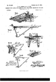
- FIG. 1 is aninverted perspective view of the preferred form of our invention.
- Fig. 2 is a longitudinal section thereof.
- Fig. 3 is an end view thereof.
- Fig. 4 is a detail view of the combined guard and pivot member.
- Fig. 5' is a perspective view, and
- Fig. 6 is a side elevation, of a modified form hereinafter described.
- Fig. 7 is a view of a portion of a our invention.
- Fig. 8 isape'rspective view of the form of attachment shown in Fig.
- Fig. 9 is a cross-section on the line 9 9 of Fig. 8 looking in the direction of arrow.
- Fig. 10 is a horizontal section on the line 10 10 of Fig. 9. several parts of the modified form of bracket separated.
- 4.0 designates a bracket formed of spring metal and consisting of two side members 40, bent into bracket shape, and one end of each of the said side members 40 is secured to the under side of the combined seat-board and guard member 50 by means of a rivet or stud 40 adapted to engage with and be made fast in any one of a series of apertures 5O in the member 50, and the secured ends of the members 40 /are held sufficiently loose on the pivots or studs 40 to allow for a limited lateral movement of the members 40 to permit of the swinging movement of the parts 40*, presently described,and for reasonshereinafter explained.
- the lower end of the members 40" is merged with upwardly, extending members 40", curved to snugly fit against the back bars 8 3 of the bicycle-frame and'having inturned lugs 40 40 for gripping said bars 3, as shown.
- the members 40* are each pivotally supported to swing laterally upon an angle-plate 12, se
- Fig. 11 illustrates the Figs. 1, 2, and 3 may have a rim 50?, whereby to adapt it to receive photograph-cameras and the like.
- Figs. 5 and 6 a slightly-modified-form of invention is shown, in which the members 40 are 'red uced to a thickness of stout wire and formed with a back turned portion 40, the ends of which terminate with hooks 40 to engage apertures in the angle-plate 12.
- This form of our invention is especially designed as a luggage-carrier.
- Figs. 7 to 11 is illustrated a further modified construction of our invention, and the same is especially adapted for a mud-guard and childs-seat attachment.
- l designates the bicycleframe, 2 the seat-post, and 3 3 the back-fork members, all of which are of the ordinary and well-known construction.
- Our improved attachment comprises, as it were, a metal bracket 4, formed of a single piece of metal bent up into shape by any suitable means, and includes a front plate a, the upper end of which is bent back into a horizontal plane, as at b, to form an attaching flange and rest 4 for the front end of the combined seat-board and guard member 5, which in practice may be covered with leather or other desired material.
- the front end of the board 5 is detachably made fast to member a by the countersink-screws 6 and nuts 6, as shown.
- the lower end of the plate a is forked and terminates in two rearwardly and upwardly bent arms 0, the extremities 4 of which are apertured to receive the bolts 7 and nuts 7 that make fast the board 5.
- a clamp member 8 each consistin g of a body portion (Z, preferably longer than plate 12, upon which it slides and to which each member 8 is pivoted, as at 8, to swing laterally.
- each member 8 is bent inward to form clampfianges 8", adapted to fit over the outer edges of the frame-fork members 3 3, and at a point just above the lower clamp 8 each member 8 has an inwardly-bent guide-flange 8, that extends over the rear face of the plate a of the bracket 4, the purpose of which is to maintain a firm connection between the lower end of the members 8 and the bracket 4 irrespective of the lateral adjustment of the members 8 to suit the divergence of the back forks of different bicycle-frames.
- the contacting surface of each member 8 is lined with felt or other similar material, as indicated by 9.
- a bicycle attachment comprisingacombined seat and guard portion; two opposing members pivotally mounted on said seat and guard portion, said opposing members having clips to engage the diverging back bars of a bicycle-frame, and bracket members connected at their lower ends to said opposing members, and extending upwardly and rearwardly to loosely engage the seat and guard portion, as specified and for the purposes described.
- Abicycle attachment comprising a combined seat and guard member, adapted to be supported in a horizontal position over the rear wheel of a bicycle and two opposing brace members loosely connected at one end to the rear portion of said seat member and bent upwardly at their free ends, and formed into clips adapted to engage the diverging back bars of a bicycle-frame, and means carried by said upwardly-bent portions for also engaging the front end of the seat member, as set forth.
- a bicycle attachment comprising a combined seat and guard portion; two opposing and downwardly-extending members pivotally mounted at the front end of said seat portion, said members having clips to engage the diverging back bars of a bicycle-frame; and opposing brace members connecting the lower ends of the pivoted members with the rear end of the seat portion, for the purposes specified.
- a bicycle attachment comprising a luggage carrying portion, a pair of opposing back-bar-grippingmembers,looselyconnected to the said luggage carrying portion, said gripping members having means at the upper and lower ends for clamping the back bars of the bicycle, and having their lower ends bent to form brackets to engage the lugfiage-carryin g portion, for the purposes speci- 5.
- An attachment for bicycles for the purposes described comprising a seat-board, a bracket member on the under side, said memher having a straight front plate, and clamp members pivotally secured to the outer face of said plate, whereby their lower ends will open laterally, said members having portions to grip the rear forks of a bicycle-frame, as set forth.
- a combined childs seat, luggagecarrier, and mud-guard for bicycles comprising, in combination, a bracket 4, having a straight front face I), the upper end of which is bent back to form a flange at, its
- bracket 4 lower emibifurcated and terminating in rearover the front face I), of the bracket 4, all be- I0 wardly and upwardly extending arms 0, the ing arranged substantially as shown and for board 5, detachably secured upon the flange the purposes described.
Landscapes
- Engineering & Computer Science (AREA)
- Mechanical Engineering (AREA)
- Motorcycle And Bicycle Frame (AREA)
Description
No. 704305. Patented July l5, I902.
H. m. LAMBERT & .0. H.00Y. 0 COMBINED MUD GUARD, SUPPLEMENTAL SEAT, AND PARCEL HOLDER FOR BICYCLE (Application filed July 12, 1901.) (No Model.) V r 2 Sheets-809st l.
\J Fig.5: 40' 1 m: unimwzrzks w, magi-1.1mm. \usnmmuxu. c.
r I 'Patentgd July 15, I902. H. m. LAMBERT & o. H. JOY. COMBINED MUD GUARD SUPPLEMENTAL SEAT. AND PARCEL HOLDER FOR BICYGLES.
(Application fil'ed July 12, 1901.;
(80 Model.) '2 $heeis-$heet 2.
. frame and be securely held without the aid bicycle, illustrating a further modification of UNITED STATES PATENT OFFICE.
HENRY M. LAMBERT AND OBED H. JOY, OF PORTLAND, OREGON.
COMBINED MUD-GUARD, SllPPLEMENTAL SEAT, AND PARCEL-HOLDER FOR BICYCLES.
srEcIFIoArIoN forming part in Letters Patentiltlo. 704,885, dated July 15, 1902.
Application filed July 12, 190-1. Serial No. 68,073. (No model.)
To aZZ whom it nwyconcern:
Be it known that we; HENRY M. LAMBERT and OBED H. JOY, residing at Portland, in, the county of Multnomah and State-ofOregon, have invented a new and Improved Combined Mud-Guard, Supplemental Seat, and Parcel-Holder for Bicycles, of Which'the following is a specification. V
Our invention has for its object to provide 7 a simple and inexpensive attachment for bicycles, capable of acting as a childs seat, baggage-carrier, and mud-guard, which can be instantly applied to the back fork of the.
of clamp-bolts or other nut-adj ustable means.
The invention comprehends generally a supportingbracket, a platform mounted thereon-to extend in a horizontal plane over the rear wheel and act as a mud-guard and seat, and attachingdevices carried on and forming a part of the bracket for securing the device upon the bicycle-frame, said attaching devices including -adiust'alole clip-frames adapted to fit and interlock with the back bars of the frame and adapted to firmly grip the said bars as weight is placed on the seat or platform member and in such manner as to prevent any possible accidental separation of the attachment from thebicycle-frame when in use.
The invention in its subordinate features includes certain details of construction and peculiar combination of parts, all of which will hereinafter be fully described, and particularly pointed out in the appended claims, reference being had to the accompanying drawings, in'which- Figure 1 is aninverted perspective view of the preferred form of our invention. Fig. 2 is a longitudinal section thereof. Fig. 3 is an end view thereof. Fig. 4 is a detail view of the combined guard and pivot member. Fig. 5'is a perspective view, and Fig. 6 is a side elevation, of a modified form hereinafter described. Fig. 7 is a view of a portion of a our invention. Fig. 8 isape'rspective view of the form of attachment shown in Fig. 7 connected to the hind-fork members of a bicycle-frame. Fig. 9 is a cross-section on the line 9 9 of Fig. 8 looking in the direction of arrow. Fig. 10 is a horizontal section on the line 10 10 of Fig. 9. several parts of the modified form of bracket separated.
In the preferred form of our invention, as illustrated in Figs. 1 to 4, 4.0 designates a bracket formed of spring metal and consisting of two side members 40, bent into bracket shape, and one end of each of the said side members 40 is secured to the under side of the combined seat-board and guard member 50 by means of a rivet or stud 40 adapted to engage with and be made fast in any one of a series of apertures 5O in the member 50, and the secured ends of the members 40 /are held sufficiently loose on the pivots or studs 40 to allow for a limited lateral movement of the members 40 to permit of the swinging movement of the parts 40*, presently described,and for reasonshereinafter explained. The lower end of the members 40" is merged with upwardly, extending members 40", curved to snugly fit against the back bars 8 3 of the bicycle-frame and'having inturned lugs 40 40 for gripping said bars 3, as shown. The members 40* are each pivotally supported to swing laterally upon an angle-plate 12, se
cured upon the under side of the seat 50 at its a spring-hook to engage a catch 12 in the.
In Figs. 5 and 6 a slightly-modified-form of invention is shown, in which the members 40 are 'red uced to a thickness of stout wire and formed with a back turned portion 40, the ends of which terminate with hooks 40 to engage apertures in the angle-plate 12. This form of our invention is especially designed as a luggage-carrier.
In Figs. 7 to 11 is illustrated a further modified construction of our invention, and the same is especially adapted for a mud-guard and childs-seat attachment.
In Figs. 7 to 11, l designates the bicycleframe, 2 the seat-post, and 3 3 the back-fork members, all of which are of the ordinary and well-known construction.
Our improved attachment comprises, as it were, a metal bracket 4, formed of a single piece of metal bent up into shape by any suitable means, and includes a front plate a, the upper end of which is bent back into a horizontal plane, as at b, to form an attaching flange and rest 4 for the front end of the combined seat-board and guard member 5, which in practice may be covered with leather or other desired material. The front end of the board 5 is detachably made fast to member a by the countersink-screws 6 and nuts 6, as shown. The lower end of the plate a is forked and terminates in two rearwardly and upwardly bent arms 0, the extremities 4 of which are apertured to receive the bolts 7 and nuts 7 that make fast the board 5. To each edge of the plate a, on the front face thereof, is made fast a clamp member 8, each consistin g of a body portion (Z, preferably longer than plate 12, upon which it slides and to which each member 8 is pivoted, as at 8, to swing laterally. The upper and lower ends of each member 8 are bent inward to form clampfianges 8", adapted to fit over the outer edges of the frame-fork members 3 3, and at a point just above the lower clamp 8 each member 8 has an inwardly-bent guide-flange 8, that extends over the rear face of the plate a of the bracket 4, the purpose of which is to maintain a firm connection between the lower end of the members 8 and the bracket 4 irrespective of the lateral adjustment of the members 8 to suit the divergence of the back forks of different bicycle-frames. To prevent abrasion of the back forks, the contacting surface of each member 8 is lined with felt or other similar material, as indicated by 9.
From the foregoing description, taken in connection with t-he'accompanying drawings, it is thought the advantages of our invention and the manner of its use will be readily un derstood.
To attach the improvement to an ordinary style of bicycle, it is only necessary to slip the members 8 8 over the back forks 3, it being obvious that as soon as weight is applied to the board 5 the members 8 will be caused to tightly grip and interlock with the forkbars 3 3 and maintain the attachment firmly in place.
Having thus described our invention, what we claim, and desire to secure by Letters Patent, isp 1. A bicycle attachment, comprisingacombined seat and guard portion; two opposing members pivotally mounted on said seat and guard portion, said opposing members having clips to engage the diverging back bars of a bicycle-frame, and bracket members connected at their lower ends to said opposing members, and extending upwardly and rearwardly to loosely engage the seat and guard portion, as specified and for the purposes described.
2. Abicycle attachment, comprising a combined seat and guard member, adapted to be supported in a horizontal position over the rear wheel of a bicycle and two opposing brace members loosely connected at one end to the rear portion of said seat member and bent upwardly at their free ends, and formed into clips adapted to engage the diverging back bars of a bicycle-frame, and means carried by said upwardly-bent portions for also engaging the front end of the seat member, as set forth.
3. A bicycle attachment, comprising a combined seat and guard portion; two opposing and downwardly-extending members pivotally mounted at the front end of said seat portion, said members having clips to engage the diverging back bars of a bicycle-frame; and opposing brace members connecting the lower ends of the pivoted members with the rear end of the seat portion, for the purposes specified.
4. A bicycle attachment, comprising a luggage carrying portion, a pair of opposing back-bar-grippingmembers,looselyconnected to the said luggage carrying portion, said gripping members having means at the upper and lower ends for clamping the back bars of the bicycle, and having their lower ends bent to form brackets to engage the lugfiage-carryin g portion, for the purposes speci- 5. An attachment for bicycles for the purposes described, comprising a seat-board, a bracket member on the under side, said memher having a straight front plate, and clamp members pivotally secured to the outer face of said plate, whereby their lower ends will open laterally, said members having portions to grip the rear forks of a bicycle-frame, as set forth.
6. As a new article, a combined childs seat, luggagecarrier, and mud-guard for bicycles, comprising, in combination, a bracket 4, having a straight front face I), the upper end of which is bent back to form a flange at, its
lower emibifurcated and terminating in rearover the front face I), of the bracket 4, all be- I0 wardly and upwardly extending arms 0, the ing arranged substantially as shown and for board 5, detachably secured upon the flange the purposes described.
a and arms 0, and the members 8, pivotally secured on the front face 5 of the bracket 4, each having inwardly-bent clamp members 8 8, on the front face to engage the rear- Witnesses:
fork bars of a. bicycle, and inwardly-extend- A. W. LAMBERT,
ing guide-flanges 8", on the rear face to close GEO. H. KILNER.
Priority Applications (1)
| Application Number | Priority Date | Filing Date | Title |
|---|---|---|---|
| US6807301A US704885A (en) | 1901-07-12 | 1901-07-12 | Combined mud-guard, supplemental seat, and parcel-holder for bicycles. |
Applications Claiming Priority (1)
| Application Number | Priority Date | Filing Date | Title |
|---|---|---|---|
| US6807301A US704885A (en) | 1901-07-12 | 1901-07-12 | Combined mud-guard, supplemental seat, and parcel-holder for bicycles. |
Publications (1)
| Publication Number | Publication Date |
|---|---|
| US704885A true US704885A (en) | 1902-07-15 |
Family
ID=2773416
Family Applications (1)
| Application Number | Title | Priority Date | Filing Date |
|---|---|---|---|
| US6807301A Expired - Lifetime US704885A (en) | 1901-07-12 | 1901-07-12 | Combined mud-guard, supplemental seat, and parcel-holder for bicycles. |
Country Status (1)
| Country | Link |
|---|---|
| US (1) | US704885A (en) |
Cited By (3)
| Publication number | Priority date | Publication date | Assignee | Title |
|---|---|---|---|---|
| US5299832A (en) * | 1991-09-24 | 1994-04-05 | Ted L. Price | Rear fender support for motorcycle |
| US20040020953A1 (en) * | 2002-08-02 | 2004-02-05 | Ed Kopidlansky | Motorcycle luggage rack system |
| US20140033961A1 (en) * | 2011-04-20 | 2014-02-06 | Vincent de Troz | Mobile ballast device |
-
1901
- 1901-07-12 US US6807301A patent/US704885A/en not_active Expired - Lifetime
Cited By (4)
| Publication number | Priority date | Publication date | Assignee | Title |
|---|---|---|---|---|
| US5299832A (en) * | 1991-09-24 | 1994-04-05 | Ted L. Price | Rear fender support for motorcycle |
| US20040020953A1 (en) * | 2002-08-02 | 2004-02-05 | Ed Kopidlansky | Motorcycle luggage rack system |
| US20140033961A1 (en) * | 2011-04-20 | 2014-02-06 | Vincent de Troz | Mobile ballast device |
| US9038554B2 (en) * | 2011-04-20 | 2015-05-26 | Vincent de Troz | Mobile ballast device |
Similar Documents
| Publication | Publication Date | Title |
|---|---|---|
| US704885A (en) | Combined mud-guard, supplemental seat, and parcel-holder for bicycles. | |
| US556951A (en) | And joseph ii | |
| US573034A (en) | Snow-shoe attachment for bicycles | |
| US481890A (en) | blood | |
| US398945A (en) | Luggage-carrier for bicycles | |
| US615106A (en) | Bicycle attachment | |
| US636155A (en) | Device for coupling bicycles. | |
| US730193A (en) | Bicycle trailer package-carrier. | |
| US1164207A (en) | Tandem seat for bicycles or motor-cycles. | |
| US1124924A (en) | Bracket for supporting the prestolite-tanks on motor-cycles. | |
| US1508107A (en) | Device for tandem seats for motor cycles | |
| US550501A (en) | Half to henry a | |
| US571302A (en) | Bicycle | |
| US560187A (en) | Maurice e | |
| US480760A (en) | Maurice e | |
| US479846A (en) | sager | |
| US520245A (en) | Bicycle mud-guard | |
| US534868A (en) | James m | |
| US548621A (en) | Auxiliary seat for bicycles | |
| US660216A (en) | Cyclist's brace and back-support. | |
| US568085A (en) | Carrying attachment for bicycles | |
| US579279A (en) | Alexander mccormack | |
| US421936A (en) | Velocipede-han ole | |
| US534326A (en) | Bicycle-saddle | |
| US565067A (en) | Runner for bicycle-wheels |