US7037188B2 - Systems for delivering conditioned air to personal breathing zones - Google Patents
Systems for delivering conditioned air to personal breathing zones Download PDFInfo
- Publication number
- US7037188B2 US7037188B2 US10/820,083 US82008304A US7037188B2 US 7037188 B2 US7037188 B2 US 7037188B2 US 82008304 A US82008304 A US 82008304A US 7037188 B2 US7037188 B2 US 7037188B2
- Authority
- US
- United States
- Prior art keywords
- air
- bed
- boom
- delivery system
- tower
- Prior art date
- Legal status (The legal status is an assumption and is not a legal conclusion. Google has not performed a legal analysis and makes no representation as to the accuracy of the status listed.)
- Expired - Fee Related
Links
Images


Classifications
-
- A—HUMAN NECESSITIES
- A47—FURNITURE; DOMESTIC ARTICLES OR APPLIANCES; COFFEE MILLS; SPICE MILLS; SUCTION CLEANERS IN GENERAL
- A47C—CHAIRS; SOFAS; BEDS
- A47C21/00—Attachments for beds, e.g. sheet holders or bed-cover holders; Ventilating, cooling or heating means in connection with bedsteads or mattresses
- A47C21/04—Devices for ventilating, cooling or heating
- A47C21/042—Devices for ventilating, cooling or heating for ventilating or cooling
- A47C21/044—Devices for ventilating, cooling or heating for ventilating or cooling with active means, e.g. by using air blowers or liquid pumps
-
- F—MECHANICAL ENGINEERING; LIGHTING; HEATING; WEAPONS; BLASTING
- F24—HEATING; RANGES; VENTILATING
- F24F—AIR-CONDITIONING; AIR-HUMIDIFICATION; VENTILATION; USE OF AIR CURRENTS FOR SCREENING
- F24F1/00—Room units for air-conditioning, e.g. separate or self-contained units or units receiving primary air from a central station
- F24F1/0007—Indoor units, e.g. fan coil units
- F24F1/0071—Indoor units, e.g. fan coil units with means for purifying supplied air
- F24F1/0073—Indoor units, e.g. fan coil units with means for purifying supplied air characterised by the mounting or arrangement of filters
-
- F—MECHANICAL ENGINEERING; LIGHTING; HEATING; WEAPONS; BLASTING
- F24—HEATING; RANGES; VENTILATING
- F24F—AIR-CONDITIONING; AIR-HUMIDIFICATION; VENTILATION; USE OF AIR CURRENTS FOR SCREENING
- F24F3/00—Air-conditioning systems in which conditioned primary air is supplied from one or more central stations to distributing units in the rooms or spaces where it may receive secondary treatment; Apparatus specially designed for such systems
- F24F3/12—Air-conditioning systems in which conditioned primary air is supplied from one or more central stations to distributing units in the rooms or spaces where it may receive secondary treatment; Apparatus specially designed for such systems characterised by the treatment of the air otherwise than by heating and cooling
- F24F3/16—Air-conditioning systems in which conditioned primary air is supplied from one or more central stations to distributing units in the rooms or spaces where it may receive secondary treatment; Apparatus specially designed for such systems characterised by the treatment of the air otherwise than by heating and cooling by purification, e.g. by filtering; by sterilisation; by ozonisation
- F24F3/163—Clean air work stations, i.e. selected areas within a space which filtered air is passed
-
- A—HUMAN NECESSITIES
- A61—MEDICAL OR VETERINARY SCIENCE; HYGIENE
- A61F—FILTERS IMPLANTABLE INTO BLOOD VESSELS; PROSTHESES; DEVICES PROVIDING PATENCY TO, OR PREVENTING COLLAPSING OF, TUBULAR STRUCTURES OF THE BODY, e.g. STENTS; ORTHOPAEDIC, NURSING OR CONTRACEPTIVE DEVICES; FOMENTATION; TREATMENT OR PROTECTION OF EYES OR EARS; BANDAGES, DRESSINGS OR ABSORBENT PADS; FIRST-AID KITS
- A61F7/00—Heating or cooling appliances for medical or therapeutic treatment of the human body
- A61F2007/0059—Heating or cooling appliances for medical or therapeutic treatment of the human body with an open fluid circuit
- A61F2007/006—Heating or cooling appliances for medical or therapeutic treatment of the human body with an open fluid circuit of gas
-
- A—HUMAN NECESSITIES
- A61—MEDICAL OR VETERINARY SCIENCE; HYGIENE
- A61F—FILTERS IMPLANTABLE INTO BLOOD VESSELS; PROSTHESES; DEVICES PROVIDING PATENCY TO, OR PREVENTING COLLAPSING OF, TUBULAR STRUCTURES OF THE BODY, e.g. STENTS; ORTHOPAEDIC, NURSING OR CONTRACEPTIVE DEVICES; FOMENTATION; TREATMENT OR PROTECTION OF EYES OR EARS; BANDAGES, DRESSINGS OR ABSORBENT PADS; FIRST-AID KITS
- A61F7/00—Heating or cooling appliances for medical or therapeutic treatment of the human body
- A61F2007/0094—Heating or cooling appliances for medical or therapeutic treatment of the human body using a remote control
-
- F—MECHANICAL ENGINEERING; LIGHTING; HEATING; WEAPONS; BLASTING
- F24—HEATING; RANGES; VENTILATING
- F24F—AIR-CONDITIONING; AIR-HUMIDIFICATION; VENTILATION; USE OF AIR CURRENTS FOR SCREENING
- F24F2221/00—Details or features not otherwise provided for
- F24F2221/10—Details or features not otherwise provided for combined with, or integrated in, furniture
-
- F—MECHANICAL ENGINEERING; LIGHTING; HEATING; WEAPONS; BLASTING
- F24—HEATING; RANGES; VENTILATING
- F24F—AIR-CONDITIONING; AIR-HUMIDIFICATION; VENTILATION; USE OF AIR CURRENTS FOR SCREENING
- F24F2221/00—Details or features not otherwise provided for
- F24F2221/12—Details or features not otherwise provided for transportable
-
- F—MECHANICAL ENGINEERING; LIGHTING; HEATING; WEAPONS; BLASTING
- F24—HEATING; RANGES; VENTILATING
- F24F—AIR-CONDITIONING; AIR-HUMIDIFICATION; VENTILATION; USE OF AIR CURRENTS FOR SCREENING
- F24F2221/00—Details or features not otherwise provided for
- F24F2221/38—Personalised air distribution
Definitions
- This invention relates to systems for delivering conditioned air to personal breathing zones. More particularly, this invention relates to systems in the personal environment that deliver conditioned air to improve health or comfort.
- otitis media e.g. ear ache
- the first line of defense against these disease's symptoms recommended by allergists is to reduce environmental exposure. This can be accomplished by removing the allergen source (for example cats, cigarettes, molds, etc.), its reservoir (for example carpets, drapes, etc.) and also by cleaning the air through the use of high-efficiency air cleaners.
- the allergen source for example cats, cigarettes, molds, etc.
- its reservoir for example carpets, drapes, etc.
- the invention provides a system to significantly improve the air quality in a personal breathing environment.
- Air quality can be improved by one or more of the following: removing allergens and other harmful particles from an air stream prior to the air stream reaching the personal breathing environment; preventing allergens and other harmful particles from reaching the personal breathing environment; and conditioning the air in the personal breathing environment.
- the invention comprises a blower unit, a delivery system that delivers air provided by the blower unit to a person's breathing zone, and a conduit that interconnects the blower unit and the delivery system for directing air from the blower unit to the delivery system.
- the delivery system is positioned so that it sends conditioned air around a persons head and into their personal breathing zone.
- the air delivered by the delivery system creates a zone of conditioned air around the persons head. Allergens and other harmful particles are prevented from entering the zone of conditioned air, so that the air being breathed in by the person is substantially the conditioned air delivered by the delivery system.
- the delivery system is positioned relative to a bed for delivering conditioned air around the head of a person or persons laying on the bed.
- the delivery system can also be positioned relative to a person sitting or laying on a chair, sofa or other piece of furniture for delivering conditioned air around that persons head, or positioned within a vehicle for delivering conditioned air around the head of an occupant of the vehicle.
- the delivery system can be used in any location where it would be desirable to deliver conditioned air around a persons head while that person is sitting, standing or laying down.
- the blower unit is preferably provided with a high efficiency filter which filters the air prior to being delivered to the breathing zone.
- the air can also be conditioned in other manners, for example heating or cooling the air, humidifying the air, introducing aromas and medicines into the air, and the like.
- FIG. 1 is a schematic representation of the system of the invention, depicting a blower unit delivering air to a delivery system.
- FIG. 2 illustrates an embodiment of the invention arranged relative to a bed.
- FIG. 3 illustrates the system of FIG. 2 with the bed removed for clarity.
- FIG. 4 illustrates another embodiment of the invention.
- FIG. 5 illustrates yet another embodiment of the invention.
- FIG. 6 illustrates yet another embodiment of the invention.
- FIG. 7 illustrates yet another embodiment of the invention.
- FIG. 8 illustrates yet another embodiment of the invention.
- FIG. 9 illustrates yet another embodiment of the invention.
- FIG. 10 illustrates yet another embodiment of the invention.
- FIG. 11 is an exploded view of another embodiment of the invention.
- FIG. 11A illustrates the boom of FIG. 11 with the fabric cover in place on the frame.
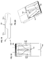
- FIG. 12 is a view of the embodiment of FIG. 11 in an assembled condition.
- FIG. 13 is a top view of the embodiment of FIG. 11 .
- FIGS. 14A and 14B illustrate the effect of an air dam created by the air delivery system of FIGS. 11–13 .
- FIG. 15 illustrates how the air leaves through the fabric of the air delivery system.
- FIG. 16 is a detailed view of another embodiment of a delivery system, with the fabric cover removed to illustrate the grill.
- FIG. 17 illustrates a portion of the air delivery conduit, with portions broken away to show the vertical height adjustment feature.
- FIG. 18 is a side view of an embodiment of the blower unit.
- FIG. 19 is a top view of the blower unit of FIG. 18 , with a portion of the top cover removed for clarity.
- FIG. 20 is a perspective view of the blower unit-of FIG. 18 with a portion of the top cover removed to show internal details.
- FIG. 21 is a view of another embodiment of an air delivery system.
- FIGS. 22A–C illustrate another embodiment of the invention that utilizes a pivoting air delivery system.
- FIGS. 23A–C illustrate another embodiment of the invention that utilizes another embodiment of an air delivery system.
- FIG. 24 is a diagram illustrating exemplary temperature conditions achieved utilizing the embodiment of FIG. 11 .
- the present invention provides a system 10 for delivering conditioned air around one or more person's head, i.e. in their personal breathing zone.
- the system 10 includes a blower unit 12 , a delivery system 14 , and a conduit 16 that interconnects the blower unit 12 and the delivery system 14 for directing air from the blower unit to the delivery system.
- the blower unit 12 is preferably provided with a high efficiency filter which filters the air prior to being delivered to the breathing zone.
- the air can also be conditioned in other manners, for example by one or more of heating or cooling the air, humidifying the air, introducing aromas and medicines into the air, and other conditioning.
- the delivery system 14 is preferably arranged near a persons head so that it delivers the conditioned air around the person's head and into their personal breathing zone, thereby improving the quality of the air that is breathed by the person.
- the conditioned air that is delivered helps to keep ambient air, which can contain a high level of allergens, from being breathed in by the person by creating a zone of conditioned air around the person's head.
- the preferred embodiment(s) will be described herein with respect to delivering conditioned air to the personal breathing zone of a person laying on a bed. It is to be realized that the system 10 could be utilized in other environments as well, for example delivering conditioned air to a person sitting or laying on a chair or sofa, or while a person is situated in a motor vehicle.
- a system 20 that is similar to the system 10 is shown relative to a bed 21 .
- the bed 21 is illustrated as being able to accommodate two sleeping adult individuals. However, it is to be realized that the bed 21 can be any size bed, including single, double, twin, queen or king sized, accommodating adults or children.
- the system 20 includes a blower unit 22 , a delivery system 24 and a conduit 26 connecting the blower unit 22 to the delivery system 24 .
- the blower unit 22 preferably includes a blower wheel (not shown) driven by an electric motor (not shown) for creating a flow of air.
- a high efficiency filter 28 such as a HEPA filter, is disposed in the blower unit 22 for filtering the air.
- the filter 28 is preferably at least about 80% efficient at removing respirable particles at least 0.3 microns and greater in size, more preferably the filter is at least about 90% efficient at removing respirable particles at least 0.3 microns and greater in size, and most preferably the filter 28 is at least about 95% efficient at removing respirable particles at least 0.3 microns and greater in size.
- the filter is 95% efficient as it exits the filter 28 , the air that is breathed in by the person within the zone of conditioned air is 95% free of respirable particles at least 0.3 microns and greater in size.
- the conduit 26 includes a duct 30 a that connects to the blower unit 22 and receives the airflow therefrom.
- a second duct 30 b is connected to the duct 30 a for delivering air to opposite sides of the bed 21 .
- Each end of the duct 30 b is connected to a riser duct 30 c , each of which extends upwardly from adjacent the end of the bed from the floor up to the delivery system 24 to deliver air to the delivery system 24 .
- the blower unit 22 , the duct 30 a and the duct 30 b are sized to enable them to fit underneath the bed 21 resting on the floor, thereby minimizing their visibility.
- the delivery system 24 extends the width of the bed 21 between the riser ducts 30 c , and is located at the end of the bed where a headboard may often be located.
- the delivery system is positioned to blow air across the tops of the pillows so that conditioned air would be delivered around the heads and into the personal breathing zones of each person laying on the bed.
- the delivery system 24 could extend along only a portion of the width of the bed, in which case conditioned air would be delivered around the head of only one person.
- the second riser duct 30 a would not be necessary.
- the delivery system 24 comprises a generally hollow structure defined by a front panel 32 that is designed to permit air to flow therethrough, and an air impermeable rear panel 34 .
- the delivery system 24 is connected to the riser ducts 30 c in such a manner as to permit conditioned air to flow from the riser ducts into the interior of the system 24 .
- the front panel 32 is made of, for example, air permeable or perforated fabric.
- the front panel 32 can be made of a hard plastic material that is provided with perforations or holes to permit air flow through the front panel 32 .
- the rear panel 34 can be formed of any suitable air impermeable material, such as fabric or a hard plastic.
- a fabric rear panel 34 together with a fabric front panel 32 will define a system 24 that can collapse upon itself when airflow is not being provided by the blower unit 22 , and which will reexpand when airflow is provided.
- the use of a plastic rear panel 34 together with a plastic front panel will define a system 24 that maintains its shape when airflow is not provided.
- the system 24 is positioned so that conditioned air that flows into the system 24 and out through the front panel 32 is directed around the heads of the individuals laying on the bed and into their breathing zone. As a result, the individuals breath in conditioned air that is substantially free of allergens.
- the system 24 is also provided with a deflector 36 along the top edge thereof for deflecting air downward and out toward the individuals on the bed.
- the front panel 32 can be provided with vent holes 38 adjacent the top edge thereof.
- the vent holes 38 create an air dam or air deflector above the air delivery area.
- the riser ducts 30 c can be adjustable vertically to enable adjustment of the vertical height of the system 24 .
- controls for controlling operation of the blower unit 22 can be incorporated into the riser ducts 30 c or into the system 24 .
- a handheld remote control unit can be provided, with the remote control unit operating via suitable known wireless technology to control blower unit operation.
- FIG. 6 illustrates a delivery system 54 that is connected to or integrated into the sides of the bedframe or the mattress.
- Conditioned air is introduced into a conduit 56 which is connected to or integrated into the bedframe or mattress at the foot end thereof, which directs the conditioned air to the system 54 .
- FIG. 8 illustrates a delivery system 74 that comprises delivery wands that extend over the pillows on the bed.
- the system 74 is configured so that it delivers conditioned air downward toward the individuals.
- FIG. 9 illustrates a delivery system 84 in the form of a shower head like device that extends over the pillows on the bed.
- the system 84 delivers conditioned air downward toward each pillow.
- FIG. 10 illustrates a delivery system 94 that comprises a quarter round arrangement where the flat sides of the system 94 are substantially air impermeable, while the arcuate side of the system 94 is air permeable to direct air both downwardly toward and above the pillows.
- the boom 104 is a multi-piece construction comprising a rear housing section 110 , a forward housing section 112 , and an air outlet section 114 .
- the housing sections 110 , 112 connect together to define a generally hollow structure defining a passage for the flow of air.
- the boom 104 decreases or tapers in size from the end that connects to the tower 106 to its free, unattached end, whereby the airflow passage also decreases in size.
- the housing sections 110 , 112 can be made of a material, for example plastic, that is generally impermeable to air so that substantially all of the air that enters the boom 104 exits through the opening 116 and the outlet section 114 .
- the outlet section 114 is formed by an air permeable fabric material cover 120 supported on a frame 122 .
- FIG. 11A illustrates the cover 120 in place on the frame 122
- FIGS. 11 , 12 and 13 illustrate the frame 122 without the cover 120 .
- the frame 122 is a grill-like structure formed of plastic.
- the cover 120 which in use is supported by the frame 122 , is preferably removably supported on the frame 122 to permit its removal for washing or replacement.
- the cover 120 can be a sleeve that is slid over the frame 122 .
- the cover 120 is a panel that attaches to the exterior of the frame 122 . Regardless of how the cover 120 is configured, the cover 120 preferably covers at least the exterior of the frame 122 to improve the aesthetic appearance of the boom 104 .
- the outlet section 114 has a generally curved cross-sectional shape.
- the cross-sectional shape of the outlet section 114 could have numerous configurations, including a single curved surface, a plurality of curved surfaces having differing curvatures, a series of interconnected straight segments, or a combination of straight and curved sections.
- the outlet section 114 be configured to discharge air over an arc that is sufficient to create an air dam that improves the resulting zone of conditioned air that is created.
- air from the top of the outlet section exits generally parallel to the bed surface, while air from the bottom of the outlet section exits generally perpendicular to the bed surface.
- the air from the bottom of the outlet section tends to entrain unfiltered air and pull the unfiltered air downward from behind the boom 104 toward the bed surface. This results in an increase in the amount of contaminated air that enters the zone of conditioned air, thereby decreasing the quality of the air that is within the zone.
- the boom 104 is configured so that a portion 115 of the filtered air is discharged from the outlet section 114 toward the bedframe or wall disposed behind the boom.
- This discharged air 115 creates an air dam that prevents unfiltered air from being pulled downward behind the boom 104 and into the conditioned air zone.
- the air is discharged over an arc length of from about 7.0 inch to about 8.0 inch, and an arc angle of from about 120 degrees to about 130 degrees, with about 30 degrees to about 40 degrees of arc back of vertical (shown in dashed lines), as shown in FIG. 14B .
- the air could be discharged over other arcs as well, as long as the air dam effect is created.
- the air leaving the cover 120 of the outlet section 114 tends to have a primary velocity vector that is generally perpendicular to the surface from which it exits at the range air flow rates that are later described herein, as illustrated in FIG. 15 .
- ⁇ P is the pressure drop in inches of water
- V is the velocity of air leaving the face of the fabric cover in feet per minute.
- the pressure drop across the fabric face of the cover 120 is preferably approximately 0.100 inches of water.
- the supported end of the boom 104 includes a pair of flanges 124 a , 124 b that are used to detachably secure the boom 104 to the tower 106 , as will be explained in further detail below.
- the flanges 124 a , 124 b are visible in FIG. 11A , as well as FIG. 16 which illustrates a boom that is similar to the boom 104 illustrated in FIGS. 11 , 11 A, 12 and 13 , but where the air discharge opening in the boom tapers in size such that the size of the opening decreases from one end thereof to the other end.
- the boom in FIG. 16 and the boom 104 in FIGS. 11–13 attach to the tower 106 in identical fashion.
- the tower 106 is also a multi-piece construction comprising an upper tower section 126 and a lower tower section 128 , as shown in FIGS. 11 and 17 .
- the tower sections 126 , 128 which are preferably formed of a plastic material, are generally cylindrical, with the tower section 126 configured to fit over the tower section 128 in a telescoping arrangement with a relatively close fit between the two sections, as illustrated in FIG. 17 .
- the tower section 128 disposed inside of the tower section 126 has a generally constant diameter from bottom to top, while the tower section 126 has a lower portion of generally constant diameter that transitions into an upper portion that increases in diameter.
- the conduit formed by the tower sections 126 , 128 increases in diameter as the conduit nears the top of the tower section 126 .
- the increasing diameter serves to slow and smooth the airflow through the tower 106 prior to the airflow entering the boom 104 , thereby reducing noise resulting from turbulence.
- the illustrated shape of the tower sections 126 , 128 also enhances the aesthetics of the tower 106 .
- the tower section 126 includes a notched section 130 at the top thereof where the boom 104 attached to the tower 106 .
- the notched section 130 includes a hole 132 with cut-outs 134 a , 134 b that receive the end of the boom 104 . It has been found that a diameter of the hole 132 (ignoring the cut-outs 134 a , 134 b ) of about 3.5 inches works well in serving to minimize the air velocity as it enters the boom.
- the end of the boom 104 is aligned with the hole 132 , with the flanges 124 a , 124 b aligned with the cut-outs 134 a , 134 b respectively.
- a deflection plate (shown in dashed lines in FIG. 12 ) disposed at around 45 degrees to the vertical axis of the tower 106 , or a curved deflection plate (shown in dashed lines in FIG. 12 ) can be provided in the upper end of the tower section 126 to transition air into the boom 104 .
- the lower tower section 128 is connected to a base section 136 that includes an inlet 138 to which a hose (not shown) leading from the blower unit 108 connects. It has been found that a diameter of the inlet 138 of at least about 3.0 inches works well.
- the base section 136 preferably has a substantial weight to lower the center of gravity of the unit, thereby increasing the stability of the unit.
- the base section 136 can be formed of a relatively heavy material such as metal.
- the base section 136 could be formed of plastic, and have weights attached thereto to increase its overall weight.
- the lower tower section 128 can include a deflection plate disposed at around 45 degrees to the vertical axis of the tower 106 , or a curved deflection plate can be provided in the lower end of the tower section 128 , to transition air into the tower from the inlet 138 .
- a pair of support legs 140 a , 140 b are connected to the base of the base section 136 for supporting the unit on the floor.
- the legs 140 a , 140 b are adjustably mounted so their position relative to the base section 136 , and relative to each other, can be altered. Adjustability of the support legs 140 a , 140 b is important because the system must be able to interact with the feet of numerous beds and headboards, as well as with the feet of nightstands and other furniture adjacent beds. Therefore, by making the support legs adjustable, the legs can be positioned to avoid such obstacles.
- the boom 104 is attached to the tower 106 in such a manner as to permit adjustment of the boom 104 about its own longitudinal axis la.
- the direction of the air flow from the boom 104 , and the resulting zone created around the person on the bed, can be altered by rotating the boom 104 slightly one way or the other around its own axis.
- the unit is also preferably designed so that the boom 104 can rotate about the vertical axis va of the tower as shown by the arrow in FIG. 13 , to enable the unit to be used on either the left or right side of the bed.
- the tower section 126 is preferably rotatable relative to the lower tower section 128 about the vertical axis so that the boom 104 can be positioned on the opposite side of the tower 106 from the position shown in FIG. 12 .
- the boom 104 would also need to be repositioned so that the air is discharged in the proper direction.
- the tower 106 is also height adjustable so that the height of the tower 106 , and the resulting height of the boom 104 above the bed, can be adjusted according to the user's needs. Height adjustment can be accomplished in many ways.
- One way to achieve height adjustment is shown in FIG. 17 .
- the exterior of the upper portion of the tower section 128 is provided with a threaded section 142 having a spiral groove.
- the interior surface of the tower section 126 is provided with threads 144 that engage with the groove of the threaded section 142 .
- the threaded height adjustment shown in FIG. 17 is capable of achieving infinite height adjustment within the height adjustment range permitted by the threaded section 142 and the threads 144 .
- the blower unit 108 comprises a two piece upper housing portion 150 that includes upper sections 151 a , 151 b and a lower housing portion 152 that together define a housing containing the fan 154 , the fan motor, a pair of high efficiency filters 156 , for example HEPA filters, for filtering air, and other elements necessary for operation of the blower unit 108 .
- the fan motor is preferably a DC motor, which provides less heat introduction and is quieter than an AC motor. It is preferred that readily replaceable pre-filters 157 be positioned in front of the filters 156 in order to filter some of the contaminants out of the air flow prior to the air reaching the high efficiency filters 156 .
- the pre-filters 157 are mounted to be replaceable at desired intervals, or when the pre-filters 157 become too dirty.
- the blower unit 108 includes an air inlet 158 at one end, and an air outlet 160 at the other end. As illustrated in FIG. 19 , the air entering through the inlet 158 is forced to undergo flow direction changes which helps to reduce the noise of the blower unit.
- the blower unit is preferably configured to have a height that allows it to be placed under most beds, although the blower unit can be located at other locations as well.
- the blower unit can also be provided with a number of controls, such as an on/off switch, speed controls, etc.
- the blower unit 108 can be provided with an indicator light to indicate that the pre-filters 157 need replacement.
- FIG. 21 shows a configuration of a boom 181 that is to be cantilever mounted to a tower.
- the boom 181 is in the form of an open framework 182 (shown in dashed lines in FIG. 21 ) upon which a fabric sleeve 183 is disposed.
- the sleeve 183 is preferably removably disposed on the boom 181 to allow cleaning or replacement of the sleeve.
- a portion of the sleeve is made of porous fabric to allow discharge of air toward the bed as discussed above with respect to the boom 104 .
- the porous portion preferably has generally the same extent as the outlet section 114 (e.g. extending over an arc of about 110 degrees).
- the remaining portion of the sleeve is preferably made of non-porous fabric.
- the boom 184 can have a configuration as shown in FIGS. 11 , 16 or 21 , or another configuration.
- the tower 186 includes a ball pivot 188 mounted at its upper end. The end of the boom 184 would be attached to the ball pivot 188 to allow the boom 184 to pivot between a stored position (shown in FIG. 22A ) and a use position (shown in FIG. 22B ). To accommodate the boom 184 when it is at the stored position, the tower 186 is recessed adjacent its upper end.
- the ball pivot 188 is provided with a plurality of vent holes 190 and air openings to communicate the tower air passage with the interior of the boom 184 .
- the vent holes 190 are exposed. At this position, the air from the blower unit can flow out the vent holes 190 into the room, so that the system acts as an air cleaner for the entire room.
- the vent holes 190 of the ball pivot 188 pivot to a position where the vent holes are closed by the tower, and generally all of the air from the tower air passage is forced to flow into the boom 184 .
- the system 10 when used in a bedroom environment, the system 10 should be designed to be as quiet as possible.
- One way to reduce the noise level of the system is to design the conduit 16 to reduce noise.
- This concept is illustrated in FIG. 3 , where the duct 30 a includes a sound muffling section 31 composed of acoustically transparent fabric wrapped in sound absorptive material.
- the fabric can be, for example, a spun nylon or polyethylene material.
- the sound absorptive material can be, for example, a felt, wool or foam. Other fabrics and sound absorptive materials can be utilized as well.
- the illustrated location of the sound muffling section 31 is exemplary only. Other locations for the section 31 are possible, including in the duct 30 b and/or in the duct 30 c . Further, more than one sound muffling section could be utilized.
- the inventor has discovered that slight differences in the temperature of the delivered air can make a big difference in the size and shape of the clean air profile or envelope as it extends over the person's head and shoulders. In nearly every room there is a natural temperature gradient, with air near the floor being cooler than the air above it. Many bedrooms have a 1 to 4° F. difference above the bed to underneath the bed.
- the clean air envelope maintains an acceptable size and shape when the delivered air is not lower than the surrounding air by 2° F. and not higher than the surrounding air by 1° F. If the delivered air falls below this range, the height of the clear air envelope becomes too low. If the delivered air is higher than this range, then the air envelope tends to rise instead of sweeping horizontally over the user.
- FIG. 24 A diagram illustrating various temperature conditions using the system in FIGS. 11–13 and 18 – 20 is illustrated in FIG. 24 .
- the diagram is a side view of the system relative to the bed, with the bottom of the boom positioned approximately 17 inches above the surface of the bed, although the bottom of the boom can range from between about 16 inches and about 18 inches above the surface of the bed in accordance with the invention.
- the lines represent the boundaries separating the clean air envelope from the surrounding unpurified air at a specific air temperature difference.
- the upper and lower boundaries of the envelope that is formed when the difference in temperature between the air being delivered and the surrounding air is +1° F. are represented by dashed lines indicated by arrows.
- the upper boundaries of the envelopes that are formed when the difference in temperature is 0° F., ⁇ 1° F.
- each envelope is also represented by lines indicated by arrows.
- the lower boundary of each envelope is the surfaces of the mattress and pillow. The diagram shows that when the temperature of the air from the boom is decreased, thereby increasing the temperature difference between the boom air and the surrounding air, the height of the clean air envelope is decreased.
- the temperature of the delivered air should be as close to the ambient temperature adjacent the delivery system as possible, ⁇ 2° F. Therefore, the motor used in the blower unit can be selected and designed to add some heat, for example a degree or two, to the air that is drawn in from the floor. By keeping the delivered air at a temperature close to ambient air temperature, the shape of the clean air envelope is optimized.
- the blower unit and motor should be designed to add little or no heat to the air that is drawn in from the floor.
- the cooler floor air would be delivered above the person's head and move downward toward the person's head because the air is cooler than the surrounding ambient air. Movement of the cooler air toward the person will help to create the desired clean air envelope, and may reduce the horsepower requirements of the motor.
Landscapes
- Engineering & Computer Science (AREA)
- Chemical & Material Sciences (AREA)
- Combustion & Propulsion (AREA)
- Mechanical Engineering (AREA)
- General Engineering & Computer Science (AREA)
- Ventilation (AREA)
- Chair Legs, Seat Parts, And Backrests (AREA)
- Accommodation For Nursing Or Treatment Tables (AREA)
- Central Air Conditioning (AREA)
- Duct Arrangements (AREA)
- Invalid Beds And Related Equipment (AREA)
Abstract
Description
ΔP=0.001415 *V 1.149
| Measurement | English Units | Si Units |
| Overall volumetric flowrate | 55 cfm | 1.557 m3/min |
| Surface area of fabric face of air | 1.68 ft2/242 in2 | 0.1561 m2/1561 cm2 |
| outlet section | ||
| Average velocity of air leaving | 33 ft/min | 10.06 m/min |
| fabric face of air outlet section | ||
| Velocity of |
14.4 ft/min | 4.4 m/min |
| air outlet section | ||
| Air velocity range of air leaving | ||
| fabric face: | ||
| Lower bound | 30 ft/min | 9.14 m/min |
| Upper bound | 60 ft/min | 18.28 m/min |
| Air temperature difference | ||
| range: | ||
| Lower bound | −2 F | −1.11 C |
| Upper bound | +1 F | +0.56 C |
Claims (5)
Priority Applications (5)
| Application Number | Priority Date | Filing Date | Title |
|---|---|---|---|
| US10/820,083 US7037188B2 (en) | 2003-04-08 | 2004-04-06 | Systems for delivering conditioned air to personal breathing zones |
| PCT/US2004/010782 WO2004092658A1 (en) | 2003-04-08 | 2004-04-07 | Systems for delivering conditioned air to personal breathing zones |
| EP04759248A EP1611398A1 (en) | 2003-04-08 | 2004-04-07 | Systems for delivering conditioned air to personal breathing zones |
| JP2006509797A JP2006525848A (en) | 2003-04-08 | 2004-04-07 | System for delivering conditioned air to personal breathing area |
| US11/287,138 US20060079170A1 (en) | 2003-04-08 | 2005-11-23 | Systems for delivering conditioned air to personal breathing zones |
Applications Claiming Priority (3)
| Application Number | Priority Date | Filing Date | Title |
|---|---|---|---|
| US46130603P | 2003-04-08 | 2003-04-08 | |
| US53936004P | 2004-01-27 | 2004-01-27 | |
| US10/820,083 US7037188B2 (en) | 2003-04-08 | 2004-04-06 | Systems for delivering conditioned air to personal breathing zones |
Related Child Applications (1)
| Application Number | Title | Priority Date | Filing Date |
|---|---|---|---|
| US11/287,138 Continuation US20060079170A1 (en) | 2003-04-08 | 2005-11-23 | Systems for delivering conditioned air to personal breathing zones |
Publications (2)
| Publication Number | Publication Date |
|---|---|
| US20040242148A1 US20040242148A1 (en) | 2004-12-02 |
| US7037188B2 true US7037188B2 (en) | 2006-05-02 |
Family
ID=33303900
Family Applications (2)
| Application Number | Title | Priority Date | Filing Date |
|---|---|---|---|
| US10/820,083 Expired - Fee Related US7037188B2 (en) | 2003-04-08 | 2004-04-06 | Systems for delivering conditioned air to personal breathing zones |
| US11/287,138 Abandoned US20060079170A1 (en) | 2003-04-08 | 2005-11-23 | Systems for delivering conditioned air to personal breathing zones |
Family Applications After (1)
| Application Number | Title | Priority Date | Filing Date |
|---|---|---|---|
| US11/287,138 Abandoned US20060079170A1 (en) | 2003-04-08 | 2005-11-23 | Systems for delivering conditioned air to personal breathing zones |
Country Status (4)
| Country | Link |
|---|---|
| US (2) | US7037188B2 (en) |
| EP (1) | EP1611398A1 (en) |
| JP (1) | JP2006525848A (en) |
| WO (1) | WO2004092658A1 (en) |
Cited By (38)
| Publication number | Priority date | Publication date | Assignee | Title |
|---|---|---|---|---|
| US20050250436A1 (en) * | 2002-09-04 | 2005-11-10 | Agne Nilsson | System, device and method for ventilation |
| US20060053554A1 (en) * | 2004-07-28 | 2006-03-16 | Acton Troy D | Forced air vent in siderail |
| US20060085911A1 (en) * | 2004-10-21 | 2006-04-27 | Tompkins Kurt W | Portable ventilation system |
| US20070018415A1 (en) * | 2005-07-20 | 2007-01-25 | Koch Hal D | Child transport air filtering system |
| US20080307970A1 (en) * | 2007-02-23 | 2008-12-18 | Augustine Biomedical And Design, Llc | Neck-worn air filtration device |
| US20090156112A1 (en) * | 2006-03-22 | 2009-06-18 | Koken Ltd. | Toxic gas exposure preventing system for anatomic practice room |
| US20090223368A1 (en) * | 2008-03-07 | 2009-09-10 | Augustine Biomedical And Design, Llc | Distal hose end filter |
| US20090233540A1 (en) * | 2008-03-17 | 2009-09-17 | Valentino Joseph A | Systems and methods for ventilation of a surgical table |
| US20090247065A1 (en) * | 2008-04-01 | 2009-10-01 | Airsonett Ab | Devices and methods for improvement of microvascular function |
| US20100081369A1 (en) * | 2008-09-30 | 2010-04-01 | Space David R | Personal ventilation in an aircraft environment |
| US20100101418A1 (en) * | 2008-10-06 | 2010-04-29 | Augustine Biomedical And Design, Llc | Personal air filtration device for use with bedding structure |
| WO2011042801A1 (en) | 2009-10-07 | 2011-04-14 | Airsonett Ab | Methods and devices for displacing body convection and providing a controlled personal breathing zone |
| WO2011114186A1 (en) | 2010-03-16 | 2011-09-22 | Airsonett Ab | Treatment of asthma, allergic rhinitis and improvement of quality of sleep by temperature controlled laminar airflow treatment |
| US20110247134A1 (en) * | 2010-04-09 | 2011-10-13 | Howell Charles A | Siderail accessory module |
| US8122540B2 (en) * | 2010-05-10 | 2012-02-28 | Furniture Traditions, Inc. | Bed headboard with ventilation system |
| WO2012136728A1 (en) | 2011-04-06 | 2012-10-11 | Airsonett Ab | Temperature controlled laminair air flow device |
| US20130025598A1 (en) * | 2011-07-25 | 2013-01-31 | Denise Eiseman | Oxygen delivery system |
| US20130031722A1 (en) * | 2011-08-01 | 2013-02-07 | Tin Cheung Wong | Air-conditioning bed |
| US8914922B1 (en) * | 2012-03-28 | 2014-12-23 | Charles D. Wells | Mountable fan for massage table |
| US20150084491A1 (en) * | 2013-09-25 | 2015-03-26 | Airbus Operations S.A.S. | Electronics Cabinet With Ventilation System |
| US8999027B1 (en) * | 2013-03-17 | 2015-04-07 | Randy Carroll Baxter | Self-contained system for scavenging contaminated air from above the water surface of an indoor swimming pool |
| US9144697B2 (en) | 2007-02-23 | 2015-09-29 | Augustine Biomedical And Design, Llc | Personal air filtration device |
| US20160174723A1 (en) * | 2014-12-17 | 2016-06-23 | Elwha Llc | Sleep zone air treatment systems and methods |
| US9456700B2 (en) | 2014-04-01 | 2016-10-04 | Bedair Breeze Llc | Bed apparatus |
| US20170191684A1 (en) * | 2015-11-16 | 2017-07-06 | Kurt West Tompkins | Portable Ventilation System |
| US20170321877A1 (en) * | 2016-05-09 | 2017-11-09 | John Polidoro | Wall mounted hospital bed, health care facility, or other wall (or surface) type light with ultraviolet-c germicidal (or other) air decontamination system |
| US10029797B2 (en) | 2008-09-30 | 2018-07-24 | The Boeing Company | Personal ventilation in an aircraft environment |
| US10179064B2 (en) | 2014-05-09 | 2019-01-15 | Sleepnea Llc | WhipFlash [TM]: wearable environmental control system for predicting and cooling hot flashes |
| US10258163B2 (en) | 2016-04-04 | 2019-04-16 | Ashley Furniture Industries, Inc. | Mattress permitting airflow for heating and cooling |
| DE102017124362A1 (en) * | 2017-10-18 | 2019-04-18 | SLT Schanze Lufttechnik GmbH & Co. Vermögensverwaltungs-KG | Furniture system with an air conditioning device |
| US10918758B1 (en) | 2020-05-19 | 2021-02-16 | Gregory Jerome Bess | Modular self-contained downdraft ventilation system to mitigate cross contamination of airborne pathogens |
| US10935276B2 (en) | 2015-10-20 | 2021-03-02 | Steven Michalski | Air mixing device |
| US10953248B2 (en) | 2014-12-04 | 2021-03-23 | ResMed Pty Ltd | Wearable device for delivering air |
| US11045011B2 (en) * | 2019-01-09 | 2021-06-29 | Virgil Venditto | Apparatus, system, and method for providing a climate controlled environment surrounding a bed for healthy sleep |
| WO2022078721A1 (en) | 2020-10-14 | 2022-04-21 | Airsonett Ab | Improved device for providing a clean air zone, e.g. a controlled personal breathing zone |
| US11813202B1 (en) * | 2020-04-14 | 2023-11-14 | Janice McLean | CPAP enclosure |
| US12116133B2 (en) | 2021-06-30 | 2024-10-15 | The Boeing Company | Ventilation assembly in an aircraft |
| USD1078013S1 (en) | 2022-12-20 | 2025-06-03 | John GENNARO | Bed fan |
Families Citing this family (33)
| Publication number | Priority date | Publication date | Assignee | Title |
|---|---|---|---|---|
| JP3966007B2 (en) * | 2002-02-08 | 2007-08-29 | ダイキン工業株式会社 | Sleeping capsule |
| US20050121530A1 (en) * | 2003-12-04 | 2005-06-09 | Thomas Song | System defined as thermoister for monitoring, controlling and adjusting a sleeper's environmental conditions of the space above entire bed surface |
| GB2416833B (en) * | 2004-07-30 | 2009-06-24 | David Derek Grant Spratley | Air circulation and bed-cover suspension unit for a bed |
| FR2888098B1 (en) * | 2005-07-06 | 2011-04-08 | Christine Nau | TEMPERATURE PACKING DEVICE FOR LITERARY AND SLEEPING EQUIPMENT |
| JP4750058B2 (en) * | 2007-02-27 | 2011-08-17 | 正 角田 | Operating room |
| DE102007014274A1 (en) * | 2007-03-16 | 2008-09-25 | Ltg Aktiengesellschaft | Method for tempering air in a room and wall element for room temperature |
| KR100802632B1 (en) * | 2007-03-23 | 2008-02-13 | 이정희 | A sleeping device with a heating or cooling apparatus |
| NL1035802C2 (en) * | 2008-08-08 | 2010-02-09 | Qrisp B V | Device for supplying an air flow to a bed, as well as a bed provided therewith. |
| NL1037249C2 (en) * | 2009-09-03 | 2011-03-08 | Qrisp B V | DEVICE AND METHOD FOR SUPPLYING TO AT LEAST ONE LOCATION TO BE COOLED OF A COOLED AIRFLOW. |
| WO2011091526A1 (en) * | 2010-02-01 | 2011-08-04 | Afzaal Mustafa | Multiple usage of ac for bed and other confined areas in addition to its conventional usage through moving mechanism and by creating the bed enclosure and other areas as required |
| US9687415B2 (en) * | 2010-05-13 | 2017-06-27 | The Nemours Foundation | Extrathoracic augmentation of the respiratory pump |
| US10010446B2 (en) | 2011-01-05 | 2018-07-03 | Hill-Rom Services, Inc. | Cooling system for an occupant of an occupant support and a cooling garment |
| ES2410858B2 (en) * | 2011-12-29 | 2014-05-14 | Universidad Politécnica de Madrid | BANK WITH AIR CONDITIONING MECHANISM |
| US20130252524A1 (en) * | 2012-03-26 | 2013-09-26 | Richard Jerald Lavender | Beauty salon ventilator |
| US20130267162A1 (en) * | 2012-04-09 | 2013-10-10 | Chun Long Technology Co., Ltd. | Air discharge structure of industrial cabinet |
| JP6416880B2 (en) * | 2013-04-23 | 2018-10-31 | アルテックス・アーベー | Sound attenuator |
| GB2526320B (en) * | 2014-05-21 | 2016-05-11 | Jeremy Worth Matthew | Apparatus for effecting temperature change in a bed |
| DE102014017533A1 (en) | 2014-11-21 | 2016-05-25 | Jrp Vision Ltd. | air supply |
| WO2016078773A1 (en) | 2014-11-21 | 2016-05-26 | Red Gmbh | Air-supply device |
| WO2016145515A1 (en) * | 2015-03-13 | 2016-09-22 | Solaeromed Inc. | Displacement ventilation assembly, methods and use for the treatment of sleep apnea |
| CN106168393A (en) * | 2016-07-20 | 2016-11-30 | 苏州新区枫桥净化设备有限公司 | A kind of Mobile air purifying device |
| US20180160819A1 (en) * | 2016-12-12 | 2018-06-14 | Helene F. RUTLEDGE | Sleep pod with controlled environment |
| EP3427613B1 (en) * | 2017-07-13 | 2020-10-07 | Avea Capital Ltd | Device for supplying respiratory air to a respiratory air area |
| KR102148613B1 (en) * | 2019-01-28 | 2020-10-14 | 닉스 주식회사 | System for inducing sleep using carbon dioxide |
| US12092363B2 (en) | 2019-03-12 | 2024-09-17 | Bissell Inc. | Air purifier in a furniture article |
| CN110486868A (en) * | 2019-08-23 | 2019-11-22 | 广州安捷生物安全科技股份有限公司 | A negative pressure screen and its application |
| US20210307523A1 (en) * | 2020-04-07 | 2021-10-07 | Lg Electronics Inc. | Bed |
| WO2021257850A1 (en) * | 2020-06-17 | 2021-12-23 | New York University | Containment, treatment, and removal of aerosolized viral contamination |
| EP4429524A4 (en) * | 2021-11-08 | 2025-11-19 | Airtulip Inc | SYSTEMS AND METHODS FOR AIR POLLUTION |
| US20250057689A1 (en) * | 2021-12-15 | 2025-02-20 | Parachuteadams Llc | Systems and methods for regulating temperatures around extremities |
| CN114234326A (en) * | 2022-01-04 | 2022-03-25 | 西安建筑科技大学 | A system and method for creating indoor thermal environment with IJV combined with DPV |
| CN115517889A (en) * | 2022-09-16 | 2022-12-27 | 山东第一医科大学第一附属医院(山东省千佛山医院) | Intelligent medical sanitary emergency bed and use method thereof |
| CN116687168A (en) * | 2023-06-03 | 2023-09-05 | 辽宁嘉恒智能科技有限公司 | Sleep-aiding mattress based on mobile terminal control |
Citations (37)
| Publication number | Priority date | Publication date | Assignee | Title |
|---|---|---|---|---|
| US1506904A (en) * | 1921-11-23 | 1924-09-02 | Drying Systems Inc | Equalized distribution system for fluids |
| US3101488A (en) | 1961-07-10 | 1963-08-27 | Peebles David Meade | Air purifying and ventilating means for beds |
| US3151929A (en) | 1961-02-13 | 1964-10-06 | Union Carbide Corp | Aseptic air isolation apparatus |
| US3230556A (en) | 1962-05-07 | 1966-01-25 | Shippee Wiusor | Construction for maintaining a controlled temperature environment in a bed |
| FR1448873A (en) | 1964-06-11 | 1966-08-12 | Farr Co | Air filter unit for beds |
| US3385036A (en) | 1966-09-06 | 1968-05-28 | Nasa Usa | Portable superclean air column device |
| US3462920A (en) | 1966-12-16 | 1969-08-26 | Bell S Medical Products Ltd | Gaseously formed curtains |
| US3724172A (en) | 1971-06-16 | 1973-04-03 | W Wood | Filtered air breathing zone |
| US3795092A (en) | 1971-09-02 | 1974-03-05 | R Deffeyes | Air filtering apparatus for allergy sufferers |
| US3820536A (en) | 1972-01-10 | 1974-06-28 | W Anspach | Apparatus for providing clean air at a surgical area |
| US3838556A (en) | 1973-04-06 | 1974-10-01 | Med Assists Inc | Air filtration device with oriented output |
| US3893457A (en) | 1971-06-17 | 1975-07-08 | Pielkenrood Vinitex Bv | Germ-free operating table |
| US3923482A (en) | 1972-04-12 | 1975-12-02 | James V Knab | Clean air directing apparatus |
| US3935803A (en) | 1972-10-12 | 1976-02-03 | Flanders Filters, Inc. | Air filtration apparatus |
| US4023472A (en) | 1974-06-04 | 1977-05-17 | Ciba-Geigy Corporation | Apparatus for producing a laminar flow |
| US4045192A (en) | 1975-09-06 | 1977-08-30 | Dragerwerk Aktiengesellschaft | Mobile filtering apparatus for keeping patients under aseptic conditions |
| US4140105A (en) | 1973-12-04 | 1979-02-20 | Zinon Duvlis | Gas curtain for shielding person on an operating table |
| FR2594668A1 (en) | 1986-02-21 | 1987-08-28 | Chareire Jean Louis | Portable or fixed air-conditioning system for use when sleeping |
| DE3644417A1 (en) | 1986-12-24 | 1988-07-14 | Hoelter Heinz | Hospital bed with chemisorption filter integrated at the head end and/or foot end |
| US5129928A (en) | 1991-06-26 | 1992-07-14 | Air Innovative Systems, Inc. | Environment treatment |
| US5160517A (en) | 1990-11-21 | 1992-11-03 | Hicks Richard E | System for purifying air in a room |
| JPH05141729A (en) | 1991-11-15 | 1993-06-08 | Aoki Corp | Personal clean booth |
| US5389037A (en) | 1993-07-15 | 1995-02-14 | Hale; Theodore M. | Method and apparatus for improving the respiratory efficiency of an infant |
| JPH07241318A (en) | 1994-03-04 | 1995-09-19 | Hosokawa Micron Corp | Sterilized booth |
| JPH0910075A (en) | 1995-06-30 | 1997-01-14 | Mitsubishi Electric Corp | System bed |
| US5832919A (en) | 1996-03-28 | 1998-11-10 | Kano; Yoshimi | Portable inflatable enclosure system with filtered positive pressure gas fed therein |
| US5943716A (en) * | 1998-07-29 | 1999-08-31 | Chu; Yun-Yuan | Air-conditioned bed hood for a baby |
| JP2000116725A (en) | 1998-10-19 | 2000-04-25 | Central Uni Co Ltd | Sick room |
| US6062977A (en) | 1994-03-15 | 2000-05-16 | Medical Air Products Group, Inc. | Source capture air filtering device |
| JP2000171067A (en) | 1998-12-03 | 2000-06-23 | Imai Michiko | Air cleaner |
| US6099607A (en) | 1998-07-22 | 2000-08-08 | Haslebacher; William J. | Rollably positioned, adjustably directable clean air delivery supply assembly, for use in weather protected environments to provide localized clean air, where activities require clean air quality per strict specifications |
| US6119689A (en) | 1997-02-18 | 2000-09-19 | Korman; David J. | Personal air filtering and delivery systems |
| US6261332B1 (en) | 1998-10-13 | 2001-07-17 | Bernard J. Richard | Filtration system for a bed |
| JP2002031382A (en) | 2000-07-18 | 2002-01-31 | Taisei Corp | Residential clean room |
| US20030033790A1 (en) | 2001-08-14 | 2003-02-20 | Stephen Hague | Bed air purification system |
| FR2833844A1 (en) | 2001-12-21 | 2003-06-27 | Airinspace Ltd | Mobile unit for insulating building from airborne contamination has rigid modules with independent lateral surfaces forming separate inner volumes |
| US20030150328A1 (en) | 2001-03-20 | 2003-08-14 | Tomas Hansson | Air-cleaning device and method for arranging air cleaning in sensitive environments |
Family Cites Families (19)
| Publication number | Priority date | Publication date | Assignee | Title |
|---|---|---|---|---|
| US1503904A (en) * | 1920-08-20 | 1924-08-05 | Heywood Wakefield Co | Means for producing woven reed articles |
| US2210458A (en) * | 1936-11-16 | 1940-08-06 | Lester S Keilholtz | Method of and apparatus for air conditioning |
| US2243637A (en) * | 1937-11-19 | 1941-05-27 | Lincoln Electric Co | Air conditioner |
| US3719136A (en) * | 1970-09-21 | 1973-03-06 | Nat Defence | Method and means for providing a clean area |
| US3973479A (en) * | 1975-06-23 | 1976-08-10 | Whiteley Isaac C | Floor-ceiling air circulating device |
| US4370155A (en) * | 1980-11-04 | 1983-01-25 | Armbruster Joseph M | Air circulating device |
| US4841847A (en) * | 1983-06-21 | 1989-06-27 | Shoji Hirayama | Air cleaning apparatus and construction of clean room with the same |
| US4867764A (en) * | 1988-02-19 | 1989-09-19 | Mega/Erg Inc. | Convertible air cleaner fan |
| JP2589773B2 (en) * | 1988-06-28 | 1997-03-12 | 松下冷機株式会社 | Ice making equipment such as refrigerators |
| US5225167A (en) * | 1991-12-30 | 1993-07-06 | Clestra Cleanroom Technology, Inc. | Room air sterilizer |
| US5453049A (en) * | 1994-02-23 | 1995-09-26 | Isolate, Inc. | Corner air filtration unit |
| US5564980A (en) * | 1995-02-09 | 1996-10-15 | Becker; Sydney J. | Room air quality conditioning system |
| FR2748048B1 (en) * | 1996-04-25 | 1998-07-31 | Air Strategie | TEXTILE SHEATH FOR CLOSE PROTECTION OF THE CONVEYANCE OF SENSITIVE PRODUCTS AND LAMINARY FLOW HOOD HAVING SUCH A SHEATH |
| US6473920B2 (en) * | 1999-11-12 | 2002-11-05 | Augustine Medical, Inc. | System for warming lower extremities of supine persons |
| US6484524B1 (en) * | 2001-07-12 | 2002-11-26 | Gennaty Ulanov | System of and a method of cooling an interior of a room provided with a wall air conditioning unit |
| US6711767B2 (en) * | 2002-01-30 | 2004-03-30 | Thomas Klamm | Apparatus for warming a bed |
| US6739426B2 (en) * | 2002-05-31 | 2004-05-25 | Control Components, Inc. | Low-noise pressure reduction system |
| US20060085911A1 (en) * | 2004-10-21 | 2006-04-27 | Tompkins Kurt W | Portable ventilation system |
| GB0425089D0 (en) * | 2004-11-13 | 2004-12-15 | Lussier Jean | Bed ventilator |
-
2004
- 2004-04-06 US US10/820,083 patent/US7037188B2/en not_active Expired - Fee Related
- 2004-04-07 WO PCT/US2004/010782 patent/WO2004092658A1/en not_active Ceased
- 2004-04-07 EP EP04759248A patent/EP1611398A1/en not_active Withdrawn
- 2004-04-07 JP JP2006509797A patent/JP2006525848A/en not_active Withdrawn
-
2005
- 2005-11-23 US US11/287,138 patent/US20060079170A1/en not_active Abandoned
Patent Citations (37)
| Publication number | Priority date | Publication date | Assignee | Title |
|---|---|---|---|---|
| US1506904A (en) * | 1921-11-23 | 1924-09-02 | Drying Systems Inc | Equalized distribution system for fluids |
| US3151929A (en) | 1961-02-13 | 1964-10-06 | Union Carbide Corp | Aseptic air isolation apparatus |
| US3101488A (en) | 1961-07-10 | 1963-08-27 | Peebles David Meade | Air purifying and ventilating means for beds |
| US3230556A (en) | 1962-05-07 | 1966-01-25 | Shippee Wiusor | Construction for maintaining a controlled temperature environment in a bed |
| FR1448873A (en) | 1964-06-11 | 1966-08-12 | Farr Co | Air filter unit for beds |
| US3385036A (en) | 1966-09-06 | 1968-05-28 | Nasa Usa | Portable superclean air column device |
| US3462920A (en) | 1966-12-16 | 1969-08-26 | Bell S Medical Products Ltd | Gaseously formed curtains |
| US3724172A (en) | 1971-06-16 | 1973-04-03 | W Wood | Filtered air breathing zone |
| US3893457A (en) | 1971-06-17 | 1975-07-08 | Pielkenrood Vinitex Bv | Germ-free operating table |
| US3795092A (en) | 1971-09-02 | 1974-03-05 | R Deffeyes | Air filtering apparatus for allergy sufferers |
| US3820536A (en) | 1972-01-10 | 1974-06-28 | W Anspach | Apparatus for providing clean air at a surgical area |
| US3923482A (en) | 1972-04-12 | 1975-12-02 | James V Knab | Clean air directing apparatus |
| US3935803A (en) | 1972-10-12 | 1976-02-03 | Flanders Filters, Inc. | Air filtration apparatus |
| US3838556A (en) | 1973-04-06 | 1974-10-01 | Med Assists Inc | Air filtration device with oriented output |
| US4140105A (en) | 1973-12-04 | 1979-02-20 | Zinon Duvlis | Gas curtain for shielding person on an operating table |
| US4023472A (en) | 1974-06-04 | 1977-05-17 | Ciba-Geigy Corporation | Apparatus for producing a laminar flow |
| US4045192A (en) | 1975-09-06 | 1977-08-30 | Dragerwerk Aktiengesellschaft | Mobile filtering apparatus for keeping patients under aseptic conditions |
| FR2594668A1 (en) | 1986-02-21 | 1987-08-28 | Chareire Jean Louis | Portable or fixed air-conditioning system for use when sleeping |
| DE3644417A1 (en) | 1986-12-24 | 1988-07-14 | Hoelter Heinz | Hospital bed with chemisorption filter integrated at the head end and/or foot end |
| US5160517A (en) | 1990-11-21 | 1992-11-03 | Hicks Richard E | System for purifying air in a room |
| US5129928A (en) | 1991-06-26 | 1992-07-14 | Air Innovative Systems, Inc. | Environment treatment |
| JPH05141729A (en) | 1991-11-15 | 1993-06-08 | Aoki Corp | Personal clean booth |
| US5389037A (en) | 1993-07-15 | 1995-02-14 | Hale; Theodore M. | Method and apparatus for improving the respiratory efficiency of an infant |
| JPH07241318A (en) | 1994-03-04 | 1995-09-19 | Hosokawa Micron Corp | Sterilized booth |
| US6062977A (en) | 1994-03-15 | 2000-05-16 | Medical Air Products Group, Inc. | Source capture air filtering device |
| JPH0910075A (en) | 1995-06-30 | 1997-01-14 | Mitsubishi Electric Corp | System bed |
| US5832919A (en) | 1996-03-28 | 1998-11-10 | Kano; Yoshimi | Portable inflatable enclosure system with filtered positive pressure gas fed therein |
| US6119689A (en) | 1997-02-18 | 2000-09-19 | Korman; David J. | Personal air filtering and delivery systems |
| US6099607A (en) | 1998-07-22 | 2000-08-08 | Haslebacher; William J. | Rollably positioned, adjustably directable clean air delivery supply assembly, for use in weather protected environments to provide localized clean air, where activities require clean air quality per strict specifications |
| US5943716A (en) * | 1998-07-29 | 1999-08-31 | Chu; Yun-Yuan | Air-conditioned bed hood for a baby |
| US6261332B1 (en) | 1998-10-13 | 2001-07-17 | Bernard J. Richard | Filtration system for a bed |
| JP2000116725A (en) | 1998-10-19 | 2000-04-25 | Central Uni Co Ltd | Sick room |
| JP2000171067A (en) | 1998-12-03 | 2000-06-23 | Imai Michiko | Air cleaner |
| JP2002031382A (en) | 2000-07-18 | 2002-01-31 | Taisei Corp | Residential clean room |
| US20030150328A1 (en) | 2001-03-20 | 2003-08-14 | Tomas Hansson | Air-cleaning device and method for arranging air cleaning in sensitive environments |
| US20030033790A1 (en) | 2001-08-14 | 2003-02-20 | Stephen Hague | Bed air purification system |
| FR2833844A1 (en) | 2001-12-21 | 2003-06-27 | Airinspace Ltd | Mobile unit for insulating building from airborne contamination has rigid modules with independent lateral surfaces forming separate inner volumes |
Non-Patent Citations (3)
| Title |
|---|
| "Air Innovative Systems, Inc.-Clean Air with Mite-E-Air(TM)," http:///www.webpaws.com/go2/AIS/, 1 page, Designed and Copyrighted (C) 1998-2003 (Printed Nov. 13, 2003). |
| Villaveces, J. et al., "Use of Laminar Air Flow Portable Filter in Asthmatic Children," Annals of Allergy, vol. 38, pp. 400-404 (Jun. 1977). |
| Zwemer, R. et al., "Use of Laminar Control Devices as Adjunct to Standard Environmental Control Measures in Symptomatic Asthmatic Children," Annals of Allergy, vol. 31, pp. 284-290 (Jun. 1973). |
Cited By (61)
| Publication number | Priority date | Publication date | Assignee | Title |
|---|---|---|---|---|
| US7361082B2 (en) * | 2002-09-04 | 2008-04-22 | Johnson Medical Development Pte. Ltd. | System, device and method for ventilating a room |
| US20050250436A1 (en) * | 2002-09-04 | 2005-11-10 | Agne Nilsson | System, device and method for ventilation |
| US20060053554A1 (en) * | 2004-07-28 | 2006-03-16 | Acton Troy D | Forced air vent in siderail |
| US7543583B2 (en) * | 2004-07-28 | 2009-06-09 | Hill-Rom Services, Inc. | Forced air vent in siderail |
| US20100221994A1 (en) * | 2004-10-21 | 2010-09-02 | Kurt West Tompkins | Portable ventilation system |
| US20060085911A1 (en) * | 2004-10-21 | 2006-04-27 | Tompkins Kurt W | Portable ventilation system |
| WO2006047120A3 (en) * | 2004-10-21 | 2007-05-31 | Kurt West Tompkins | Portable ventillation system |
| US20080060131A1 (en) * | 2004-10-21 | 2008-03-13 | Tompkins Kurt W | Portable Ventilation System |
| US7908688B2 (en) * | 2004-10-21 | 2011-03-22 | Kurt West Tompkins | Portable ventilation system |
| US20070018415A1 (en) * | 2005-07-20 | 2007-01-25 | Koch Hal D | Child transport air filtering system |
| US7360772B2 (en) * | 2005-07-20 | 2008-04-22 | Koch Hal D | Child transport air filtering system |
| US20090156112A1 (en) * | 2006-03-22 | 2009-06-18 | Koken Ltd. | Toxic gas exposure preventing system for anatomic practice room |
| US9375547B2 (en) | 2007-02-23 | 2016-06-28 | Augustine Biomedical And Design, Llc | Personal air filtration device |
| US9144697B2 (en) | 2007-02-23 | 2015-09-29 | Augustine Biomedical And Design, Llc | Personal air filtration device |
| US9095803B2 (en) | 2007-02-23 | 2015-08-04 | Augustine Biomedical And Design, Llc | Neck-worn air filtration device |
| US9724545B2 (en) | 2007-02-23 | 2017-08-08 | Augustine Biomedical And Design, Llc | Neck-worn air filtration device |
| US20080307970A1 (en) * | 2007-02-23 | 2008-12-18 | Augustine Biomedical And Design, Llc | Neck-worn air filtration device |
| US20090223368A1 (en) * | 2008-03-07 | 2009-09-10 | Augustine Biomedical And Design, Llc | Distal hose end filter |
| US20090233540A1 (en) * | 2008-03-17 | 2009-09-17 | Valentino Joseph A | Systems and methods for ventilation of a surgical table |
| US20090247065A1 (en) * | 2008-04-01 | 2009-10-01 | Airsonett Ab | Devices and methods for improvement of microvascular function |
| US8956442B2 (en) | 2008-04-01 | 2015-02-17 | Airsonett Ab | Devices and methods for improvement of microvascular function |
| US20100081369A1 (en) * | 2008-09-30 | 2010-04-01 | Space David R | Personal ventilation in an aircraft environment |
| US10029797B2 (en) | 2008-09-30 | 2018-07-24 | The Boeing Company | Personal ventilation in an aircraft environment |
| US20100101418A1 (en) * | 2008-10-06 | 2010-04-29 | Augustine Biomedical And Design, Llc | Personal air filtration device for use with bedding structure |
| US8414671B2 (en) | 2008-10-06 | 2013-04-09 | Augustine Biomedical And Design, Llc | Personal air filtration device for use with bedding structure |
| WO2011042801A1 (en) | 2009-10-07 | 2011-04-14 | Airsonett Ab | Methods and devices for displacing body convection and providing a controlled personal breathing zone |
| US8444747B2 (en) | 2009-10-07 | 2013-05-21 | Airsonett Ab | Methods and devices for displacing body convection and providing a controlled personal breathing zone |
| CN102667351A (en) * | 2009-10-07 | 2012-09-12 | 阿桑勒公司 | Methods and devices for displacing body convection and providing a controlled personal breathing zone |
| CN102667351B (en) * | 2009-10-07 | 2016-08-10 | 阿桑尼特有限责任公司 | Method and apparatus for displacing body convection and providing a controlled personal breathing zone |
| EP2708259A1 (en) | 2010-03-16 | 2014-03-19 | Airsonett AB | Treatment of asthma, allergic rhinitis and improvement of quality of sleep by temperature controlled laminar airflow treatment |
| WO2011114186A1 (en) | 2010-03-16 | 2011-09-22 | Airsonett Ab | Treatment of asthma, allergic rhinitis and improvement of quality of sleep by temperature controlled laminar airflow treatment |
| US20110247134A1 (en) * | 2010-04-09 | 2011-10-13 | Howell Charles A | Siderail accessory module |
| US8122540B2 (en) * | 2010-05-10 | 2012-02-28 | Furniture Traditions, Inc. | Bed headboard with ventilation system |
| WO2012136728A1 (en) | 2011-04-06 | 2012-10-11 | Airsonett Ab | Temperature controlled laminair air flow device |
| US20130025598A1 (en) * | 2011-07-25 | 2013-01-31 | Denise Eiseman | Oxygen delivery system |
| US20130031722A1 (en) * | 2011-08-01 | 2013-02-07 | Tin Cheung Wong | Air-conditioning bed |
| US8914922B1 (en) * | 2012-03-28 | 2014-12-23 | Charles D. Wells | Mountable fan for massage table |
| US8999027B1 (en) * | 2013-03-17 | 2015-04-07 | Randy Carroll Baxter | Self-contained system for scavenging contaminated air from above the water surface of an indoor swimming pool |
| US20150084491A1 (en) * | 2013-09-25 | 2015-03-26 | Airbus Operations S.A.S. | Electronics Cabinet With Ventilation System |
| CN104661493A (en) * | 2013-09-25 | 2015-05-27 | 空中客车运营简化股份公司 | Electronics cabinet with ventilation system |
| US10130011B2 (en) * | 2013-09-25 | 2018-11-13 | Airbus Operations S.A.S. | Electronics cabinet with ventilation system |
| CN104661493B (en) * | 2013-09-25 | 2018-07-06 | 空中客车运营简化股份公司 | Electronic device cabinet with ventilating system |
| US9456700B2 (en) | 2014-04-01 | 2016-10-04 | Bedair Breeze Llc | Bed apparatus |
| US10179064B2 (en) | 2014-05-09 | 2019-01-15 | Sleepnea Llc | WhipFlash [TM]: wearable environmental control system for predicting and cooling hot flashes |
| US11679287B2 (en) | 2014-12-04 | 2023-06-20 | ResMed Pty Ltd | Wearable device for delivering air |
| US10953248B2 (en) | 2014-12-04 | 2021-03-23 | ResMed Pty Ltd | Wearable device for delivering air |
| US12194322B2 (en) | 2014-12-04 | 2025-01-14 | ResMed Pty Ltd | Wearable device for delivering air |
| US20160174723A1 (en) * | 2014-12-17 | 2016-06-23 | Elwha Llc | Sleep zone air treatment systems and methods |
| US11906193B2 (en) | 2015-10-20 | 2024-02-20 | Steven Michalski | Air moving device |
| US10935276B2 (en) | 2015-10-20 | 2021-03-02 | Steven Michalski | Air mixing device |
| US20170191684A1 (en) * | 2015-11-16 | 2017-07-06 | Kurt West Tompkins | Portable Ventilation System |
| US10258163B2 (en) | 2016-04-04 | 2019-04-16 | Ashley Furniture Industries, Inc. | Mattress permitting airflow for heating and cooling |
| US10808964B2 (en) * | 2016-05-09 | 2020-10-20 | John Polidoro | Wall mounted hospital bed, health care facility, or other wall (or surface) type light with Ultraviolet-C germicidal (or other) air decontamination system |
| US20170321877A1 (en) * | 2016-05-09 | 2017-11-09 | John Polidoro | Wall mounted hospital bed, health care facility, or other wall (or surface) type light with ultraviolet-c germicidal (or other) air decontamination system |
| DE102017124362A1 (en) * | 2017-10-18 | 2019-04-18 | SLT Schanze Lufttechnik GmbH & Co. Vermögensverwaltungs-KG | Furniture system with an air conditioning device |
| US11045011B2 (en) * | 2019-01-09 | 2021-06-29 | Virgil Venditto | Apparatus, system, and method for providing a climate controlled environment surrounding a bed for healthy sleep |
| US11813202B1 (en) * | 2020-04-14 | 2023-11-14 | Janice McLean | CPAP enclosure |
| US10918758B1 (en) | 2020-05-19 | 2021-02-16 | Gregory Jerome Bess | Modular self-contained downdraft ventilation system to mitigate cross contamination of airborne pathogens |
| WO2022078721A1 (en) | 2020-10-14 | 2022-04-21 | Airsonett Ab | Improved device for providing a clean air zone, e.g. a controlled personal breathing zone |
| US12116133B2 (en) | 2021-06-30 | 2024-10-15 | The Boeing Company | Ventilation assembly in an aircraft |
| USD1078013S1 (en) | 2022-12-20 | 2025-06-03 | John GENNARO | Bed fan |
Also Published As
| Publication number | Publication date |
|---|---|
| EP1611398A1 (en) | 2006-01-04 |
| US20040242148A1 (en) | 2004-12-02 |
| JP2006525848A (en) | 2006-11-16 |
| US20060079170A1 (en) | 2006-04-13 |
| WO2004092658A1 (en) | 2004-10-28 |
Similar Documents
| Publication | Publication Date | Title |
|---|---|---|
| US7037188B2 (en) | Systems for delivering conditioned air to personal breathing zones | |
| US7036163B2 (en) | Furniture cover sheet | |
| US9095803B2 (en) | Neck-worn air filtration device | |
| US9375547B2 (en) | Personal air filtration device | |
| US8414671B2 (en) | Personal air filtration device for use with bedding structure | |
| WO2001084982A1 (en) | Ventilated sleep devices | |
| US6508850B1 (en) | Clean air tent system | |
| US20030033790A1 (en) | Bed air purification system | |
| JP2012002393A (en) | Air cleaning apparatus | |
| JP2000171067A (en) | Air cleaner | |
| CN100430660C (en) | Apparatus and method for creating a conditioned air zone above a bed surface | |
| KR200308486Y1 (en) | Bed having air-cleaner | |
| JPH05141729A (en) | Personal clean booth | |
| WO1998019646A1 (en) | Treated air supply | |
| JP3575032B2 (en) | Air purifier and air purifier | |
| JP2002039565A (en) | Air cleaner | |
| CA2485327A1 (en) | Portable breathing zone air cleaner | |
| JP2012002392A (en) | Air cleaning apparatus | |
| JPH07241340A (en) | Asthma fit preventive device | |
| JPH1172247A (en) | Locally clean air purifier | |
| JP2004163028A (en) | Air purification equipment | |
| JP2006052908A (en) | Air cleaning division device | |
| HK1139021B (en) | Personal air filtration device | |
| CN114557565A (en) | Air oxygenation humidification purification bed | |
| KR100564494B1 (en) | Suction structure of air cleaner |
Legal Events
| Date | Code | Title | Description |
|---|---|---|---|
| AS | Assignment |
Owner name: HALO INNOVATIONS, INC., MINNESOTA Free format text: ASSIGNMENT OF ASSIGNORS INTEREST;ASSIGNORS:SCHMID, WILLIAM R.;HACKER, DEAN W.;KRAUSE, ERIC J.;REEL/FRAME:015628/0017 Effective date: 20040420 |
|
| FPAY | Fee payment |
Year of fee payment: 4 |
|
| SULP | Surcharge for late payment | ||
| FPAY | Fee payment |
Year of fee payment: 8 |
|
| AS | Assignment |
Owner name: COLE TAYLOR BANK, ILLINOIS Free format text: SECURITY INTEREST;ASSIGNOR:HALO INNOVATIONS, INC.;REEL/FRAME:033161/0728 Effective date: 20140604 |
|
| AS | Assignment |
Owner name: BALANCE POINT CAPITAL PARTNERS, L.P., CONNECTICUT Free format text: SECURITY INTEREST;ASSIGNOR:HALO INNOVATIONS, INC.;REEL/FRAME:033265/0958 Effective date: 20140609 |
|
| AS | Assignment |
Owner name: ANTARES CAPITAL LP, AS ADMINISTRATIVE AGENT, ILLIN Free format text: SECURITY INTEREST;ASSIGNORS:ADEN & ANAIS, INC.;HALO INNOVATIONS, INC.;REEL/FRAME:040469/0776 Effective date: 20161130 |
|
| AS | Assignment |
Owner name: HALO INNOVATIONS, INC., MINNESOTA Free format text: RELEASE BY SECURED PARTY;ASSIGNOR:MB FINANCIAL BANK, N.A.;REEL/FRAME:040486/0748 Effective date: 20161130 Owner name: HALO INNOVATIONS, INC., MINNESOTA Free format text: RELEASE BY SECURED PARTY;ASSIGNOR:BALANCE POINT CAPITAL PARNTERS, L.P.;REEL/FRAME:040487/0115 Effective date: 20161130 |
|
| FEPP | Fee payment procedure |
Free format text: MAINTENANCE FEE REMINDER MAILED (ORIGINAL EVENT CODE: REM.) |
|
| LAPS | Lapse for failure to pay maintenance fees |
Free format text: PATENT EXPIRED FOR FAILURE TO PAY MAINTENANCE FEES (ORIGINAL EVENT CODE: EXP.) |
|
| STCH | Information on status: patent discontinuation |
Free format text: PATENT EXPIRED DUE TO NONPAYMENT OF MAINTENANCE FEES UNDER 37 CFR 1.362 |
|
| FP | Lapsed due to failure to pay maintenance fee |
Effective date: 20180502 |
|
| AS | Assignment |
Owner name: HALO INNOVATIONS, INC., NEW YORK Free format text: RELEASE BY SECURED PARTY;ASSIGNOR:ANTARES CAPITAL LP, AS ADMINISTRATIVE AGENT;REEL/FRAME:063912/0238 Effective date: 20230608 Owner name: ADEN & ANAIS, INC., NEW YORK Free format text: RELEASE BY SECURED PARTY;ASSIGNOR:ANTARES CAPITAL LP, AS ADMINISTRATIVE AGENT;REEL/FRAME:063912/0238 Effective date: 20230608 |