US7028097B2 - Wireless LAN with dynamic channel access management - Google Patents
Wireless LAN with dynamic channel access management Download PDFInfo
- Publication number
- US7028097B2 US7028097B2 US10/109,715 US10971502A US7028097B2 US 7028097 B2 US7028097 B2 US 7028097B2 US 10971502 A US10971502 A US 10971502A US 7028097 B2 US7028097 B2 US 7028097B2
- Authority
- US
- United States
- Prior art keywords
- station
- cam
- stations
- client
- message
- Prior art date
- Legal status (The legal status is an assumption and is not a legal conclusion. Google has not performed a legal analysis and makes no representation as to the accuracy of the status listed.)
- Expired - Fee Related, expires
Links
Images


Classifications
-
- H—ELECTRICITY
- H04—ELECTRIC COMMUNICATION TECHNIQUE
- H04W—WIRELESS COMMUNICATION NETWORKS
- H04W84/00—Network topologies
- H04W84/18—Self-organising networks, e.g. ad-hoc networks or sensor networks
- H04W84/20—Master-slave selection or change arrangements
-
- H—ELECTRICITY
- H04—ELECTRIC COMMUNICATION TECHNIQUE
- H04W—WIRELESS COMMUNICATION NETWORKS
- H04W84/00—Network topologies
- H04W84/02—Hierarchically pre-organised networks, e.g. paging networks, cellular networks, WLAN [Wireless Local Area Network] or WLL [Wireless Local Loop]
- H04W84/10—Small scale networks; Flat hierarchical networks
- H04W84/12—WLAN [Wireless Local Area Networks]
-
- H—ELECTRICITY
- H04—ELECTRIC COMMUNICATION TECHNIQUE
- H04W—WIRELESS COMMUNICATION NETWORKS
- H04W92/00—Interfaces specially adapted for wireless communication networks
- H04W92/16—Interfaces between hierarchically similar devices
- H04W92/18—Interfaces between hierarchically similar devices between terminal devices
Definitions
- the present invention concerns networking in general, and wireless computer networks in particular.
- WLANs wireless local area networks
- Ethernet networks such as Ethernet networks.
- WLANs are popular for use in buildings that are difficult to wire for conventional networking, such as homes and older office buildings, as well as for use in environments in which mobile computers are used and to extend the range of conventional wired networks.
- Bluetooth provides a lower-cost solution that enables devices in close proximity to communicate using a radio channel.
- IrDA Infrared Direct Access
- SWAP HomeRF
- WECA Wi-Fi
- SWAP uses a technology known as frequency-hopping spread spectrum (FHSS), wherein short bursts of data are sent between frequency shifts (hops).
- FHSS frequency-hopping spread spectrum
- SWAP networks are relatively inexpensive, in part because SWAP does not require an access point, but has limited bandwidth on the order of 1–2 Mbps (megabits per second).
- Wi-Fi wireless fidelity
- GHz 2.4-gigahertz
- Wi-Fi uses spread-spectrum radio waves in the 2.4-gigahertz (GHz) frequency range.
- DSSS direct-sequence spread spectrum
- FHSS frequency division multiple access
- a Wi-Fi WLAN 10 is shown in FIG. 1 .
- WLAN 10 includes a desktop personal computer (PC) station 12 , an APPLE MACINTOSH G-3TM computer station 14 , a UNIX workstation station 16 , a tower PC station 18 , a laptop station 20 , and a laptop station 22 , each of which is enabled to communicate with the other stations in the WLAN via a wireless access point (AP) 24 .
- a wireless AP will also provide a higher-speed network interface for connection to a conventional wired network, such as an Ethernet interface, to enable computers on a WLAN to also access a conventional wired LAN or WAN (wide area network).
- wireless AP 24 is shown in FIG. 1 as being connected to a network server 26 via an Ethernet link 28 ; however, it will be understood that a wireless AP may be implemented in configurations in which it is not connected to a LAN or WAN.
- a computer may include a wireless network adapter that includes a transceiver designed to send and receive signals in a frequency range corresponding to the WLAN's operation type (e.g., 2.4 GHz frequency range for IEEE 802.11b WLANs).
- these wireless network adapters comprise a wireless network adapter card 30 for use in PCs and a PCMCIA wireless network adapter card 32 for use in laptops.
- modern APPLETM computers may include a built-in “Airport” communication port to enable wireless network access, or implement a peripheral card in a manner similar to wireless network adapter card 30 . Similar solutions are available for workstations.
- An AP provides a basic and extended service set to one or more stations (i.e. computers) that communicate with the AP.
- the AP facilitates and coordinates communication and channel access between stations.
- Stations authenticated and associated with an AP typically do not operate in a peer-to-peer mode—communication from one station to another must route through the AP, as shown by communication paths 34 , 36 , 38 , 40 , 42 , and 44 .
- the AP serves as a relay station for data traffic between stations and, therefore, station-to-station communication takes at least twice the amount of time than if a source station could communicate directly with a target station (i.e., the source station must send data to the AP, which in turn resends the data to the target station). This results in the bandwidth of the wireless media being effectively reduced by half.
- an AP-based WLAN may require assigning IP addresses to each of the computers in the network, which may also entail a manual configuration of each computer as well.
- an additional AP or an extension point essentially an AP without a wired network interface
- FIG. 1 is a schematic diagram of a conventional wireless LAN (WLAN) that implements a wireless access point;
- WLAN wireless LAN
- FIG. 2 is a schematic diagram of an exemplary WLAN topology in accordance with one embodiment of the invention.
- FIG. 3 is a schematic diagram depicting various completed and uncompleted communication paths between the stations of the WLAN topology of FIG. 2 ;
- FIG. 4 is a schematic diagram illustrating radio interference that occurs when two stations attempt to transmit data within range of or to a common station
- FIGS. 5A and 5B collectively comprise a flowchart illustrating the logic used by one embodiment of the invention to determine the best station to use for a channel access manager (CAM);
- CAM channel access manager
- FIG. 6 is a flowchart illustrating the logic used by one embodiment of the invention when registering a proxy channel access manager (PCAM);
- PCAM proxy channel access manager
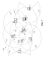
- FIG. 7 is a schematic diagram depicting the WLAN of FIG. 2 with the addition of two laptop stations and the implementation of two PCAM stations to access the new laptop stations;
- FIG. 8 is a flowchart illustrating the logic used by one embodiment of the invention when initializing a CAM client
- FIGS. 9A and 9B collectively comprise a flowchart illustrating the logic used by one embodiment of the invention when performing normal CAM operations
- FIG. 10 is a flowchart illustrating the logic used by one embodiment of the invention when performing normal PCAM operations
- FIGS. 11A and 11B collectively comprise a flowchart illustrating the logic used by one embodiment of the invention when performing normal CAM client operations
- FIG. 12 is a schematic diagram illustrating the benefit of employing a proxy station performance manager
- FIG. 13 is a flowchart illustrating the logic determine an optimal routing path to maximize transmission bandwidth
- FIG. 14 is a schematic diagram of a computer system that may be used to implement the invention.
- the present invention provides a system and method for implementing a peer-to-peer WLAN that does not require an access point, yet facilitates many of the features provided by an AP, such as channel management and Quality of Service functions.
- the invention defines a method for dynamically selecting a Channel Access Manager (CAM) that (preferably) has the ability to communicate with the greatest number of wireless stations in a given WLAN.
- CAM Channel Access Manager
- the invention also defines a method for selecting one or more proxy CAMs that establish communication paths between the CAM and wireless stations with which the CAM traditionally would not be able to communicate.
- the invention also provides a method for resolving the issues that occur when a new station is added to the WLAN, and provides optimize routing of messages to maximize transmission bandwidths.
- FIG. 3 A typical WLAN configuration 50 in which the invention may be implemented is shown in FIG. 3 .
- WLAN configuration 50 includes the same stations in substantially the same physical locations as in Wi-Fi WLAN 10 , but no longer uses access point 24 .
- FIG. 2 Also shown in FIG. 2 are arcs and a circle corresponding to respective coverage areas for each station, wherein the arc or circle for a given station has the same reference number as the station to which it is associated plus an appended “C.”
- station 12 has a coverage area represented by an arc 12 C.
- each coverage area is shown to have a constant radius from its transmission point; it will be understood that the actual coverage areas would comprise closed boundaries of various shapes rather than circles in most instances due to interferences discussed below.
- the arcs used on FIG. 2 are representative of partial coverage areas of their corresponding station, and are used in the figure to reduce its size.
- the invention may be implemented using IEEE 802.11b compatible devices.
- IEEE 802.11b compatible devices have a transmission range of 1000 feet or less in open areas and 250–400 feet in closed areas (due to interference caused by physical structures such as walls). These transmission ranges can be reduced even further if radio frequency (RF) interference conditions exist, such as RF signals transmitted to or from nearby cellular towers.
- RF radio frequency
- FIG. 3 Various peer-to-peer communications paths corresponding to WLAN configuration 50 are shown in FIG. 3 .
- Successful communication paths are shown as “lightning bolts,” and include communication paths 52 , 54 , 56 , 58 , 60 , 62 , 64 , and 66 .
- Each of these communication paths identifies that the pair of stations connected by the communication path are proximate enough to communicate with each other under current operating conditions.
- Also shown in FIG. 3 are incomplete communication paths, which comprise dashed lines covered with a “NO” symbol (i.e., a circle with a angled bar crossing it). These include incomplete paths 70 , 72 , 74 , 76 , 78 , and 80 .
- An incomplete communication path indicates that the two stations to which the path connects are not close enough to each other to enable satisfactory communication.
- FIG. 3 There are two immediate problems illustrated in FIG. 3 .
- the most obvious problem is the incomplete communication paths.
- One of the primary features of a LAN is that each station may access any other station in the network. As discussed above, this function is normally provided by the access point, which no longer exists.
- a less obvious problem concerns “hidden” stations.
- a hidden station is a station that is unknown (i.e. out of range, and thus not “visible”) to another station in the network. This creates problems because transmissions between one set of peer stations may inadvertently interfere with transmissions between another set of peer stations.
- station 16 was in the process of transmitting data to station 18 via transmission signals 86 . Since station 16 is out-of-range from either of stations 20 or 22 , neither of these latter stations will know that station 16 is transmitting to station 18 . However, station 18 is in range of all of stations 16 , 20 , and 22 .
- transmission signals 84 will be received by station 18 as well as the station targeted for reception of the signal (station 22 ), since transmitted signals are substantially transmitted as omni-directional RF signals from their transmission point, as depicted by signals 84 in FIG. 4 , rather than the unidirectional transmission paths shown in FIG. 3 .
- a signal interference region 88 is created, wherein any reception point (e.g., station 18 ) within the signal interference region may have reception problems when it receives signals that are transmitted concurrently from two or more different stations that are within range of the reception point.
- the invention employs a combination of CAMs, proxy CAMs (PCAMs), and client CAMs (CCs), as described below.
- the first operation when establishing a new WLAN configuration is to determine which station(s) in the network shall be assigned to operate as (the) CAM(s).
- this process begins in a block 100 in which automatic configuring of the wireless stations is performed during a timeframe known as the “startup” period.
- each of the wireless stations will obtain a valid Internet Protocol (IP) address.
- IP Internet Protocol
- the IP addresses are obtained using an industry standard auto-configuration process.
- an “Access Manager Arbitration” (AMA) period begins in a block 102 , during which each station becomes a New CAM candidate (NCC).
- NCC stations monitor the channel for the presence of a Priority Client Access (PCA) message, as depicted by a decision block 104 .
- the channel is selected as the NCC scans all channels looking for the active channel, i.e. the channel where the PCA message is being transmitted.
- the length of the PCA message is such that it exceeds the maximum time required for a scan of all channels by a potential receiving station.
- the NCC upon detection of the PCA message, the NCC is able to determine the station identity of the CAM (or PCAM) and begins to execute an CAM Client protocol as defined below.
- the station When an NCC does not detect a PCA message before the expiration of the AMA period (as indicated by a YES result for a decision block 108 ), the station becomes a CAM candidate (CAMC) and executes a channel Access Manager arbitration protocol.
- each CAMC attempts channel access in accordance with channel access methods defined by the IEEE 802.11 specification (1999) on a repeated basis until a channel is successfully accessed.
- a CAMC transmits a Station Identification Request message (SIDR) to all other stations in a block 114 .
- SIDR Station Identification Request message
- Each wireless station that is in communication range of the CAMC will respond to the SDIR with a Station Identification (SID) message packet.
- SID Station Identification
- the SID response contains respondent station identification information (e.g., IP address, MAC address, and other pertinent station identification information).
- the CAMC increments it SID count and logs the response.
- AMI Access Manager Arbitration Gap
- a CAMC attempts to access the channel until successful in accordance with blocks 124 and 126 , and then transmits an Access Manager Information (AMI) message in a block 128 .
- the AMI message contains the CAMC station identification information, the number of responses the CAMC received to its SIDR message, and station identifiers for each of the responses.
- a decision block 130 if an SIDR message is received during this time frame, the channel is accessed in a block 132 , and a SID message is transmitted in a block 134 .
- each receiving CAMC In response to receiving an AMI message, each receiving CAMC will compare the SIDR response count sent with the message with its own SIDR response count. If a receiving CAMC determines that its response count is larger, it will transmit its own AMI message over the channel; otherwise, it will not respond. CAMC stations with a higher response count must begin transmission of their AMI message within a period defined as the AMI Response GAP (ARG), which begins when the previous CAMC has completed transmission of its AMI message. Accordingly, a determination is made in a decision block 136 to whether the ARG has ended. If it has not, a determination is made in a decision block 138 to whether an AMI message is received. If it has not the logic loops back to decision block 136 . If an AMI message is received, the AMI count for the CAMC is incremented in a block 140 and AMI message data is logged in a block 142 , returning the logic to decision block 136 .
- AMI Response GAP AMI Response GAP
- This CAMC becomes the CAM and the logic proceeds to begin CAM operations in a block 146 . If the AMI count>0, which will be the case for all of the other CAMC's in the WLAN, a proxy CAM registration process is began in a block 148 to determine whether any of these CAMC's qualify as proxy CAMs.
- the last CAMC to transmit an AMI message before the ARG expires becomes the CAM.
- This method ensures that the greatest number of stations in the WLAN have the station identifier of the CAM.
- the station that becomes the CAM is then used to manage channel access for all wireless station communication in the network, as described below with reference to FIGS. 9A and 9B .
- the foregoing CAM selection algorithm was applied to WLAN configuration 50 .
- all of stations 12 , 14 , 16 , 18 , 20 , and 22 would initially qualify as CAMCs.
- the SIDR response count corresponds to the count of all stations that response to a given CAMC's SIDR message.
- the number of responses for each station will correspond to the number of transmission areas in which each station resides (outside of its own transmission area). For instances, station 12 falls within transmission areas 14 C, 18 C, and 22 C, so its count is 3 .
- proxy CAM initialization is performed as follows. Proxy CAMs begin their existence as a CAM Candidate with an AMI message count greater than 0. CAMC stations with an AMI count greater than zero have a record of the CAM station identifier as well as the identifiers of the stations with whom the CAM is able to communicate. The following operations are applied to each CAMC, with the objective of identifying any CAMC's that are able to communicate with both the CAM and another CAMC that is not within communication range with the CAM.
- the CAMC performs a comparison of the CAM station identifiers with the station identifiers the CAMC received in its SIDR response messages. From this information, a determination can be made in a decision block 152 to whether there are any stations the CAMC can see that can't be seen by the CAM.
- a CAMC becomes a CC when all of the stations identifiers from its own SIDR responses compare with the station identifiers in the AMI message from the CAM. This corresponds to a NO result from decision block 152 , whereupon the CAMC becomes a CAM client (CC), and client operations are began in a block 154 as described below with reference to FIGS. 11A and 11B .
- a CAMC SID list includes a SID that is not included in the CAM SID list
- the answer to decision block 152 is YES, and the logic proceeds to blocks 156 and 158 , wherein an attempt to access the channel is made until successful.
- the CAMC then sends a PCM (proxy CAM Message) in a block 160 , and begins PCAM operation in a block 162 .
- PCM proxy CAM Message
- WLAN configuration 50 A is identical to WLAN configuration 50 , except for the addition of a wireless stations 23 and 25 which respectively have corresponding coverage area 23 C and 25 C.
- station 16 which is not the CAM (i.e. station 18 ). Accordingly, station 16 becomes a proxy CAM.
- station 22 the only other station within coverage area 25 C is station 22 , which also becomes a PCAM.
- stations 23 and 25 are now enabled to join the WLAN, wherein CAM station 18 is enabled to communicate with station 23 via PCAM station 16 and with station 25 via PCAM station 22 . It is further noted that if station 18 was an access point with the same coverage that the additions of stations 23 and 25 to the WLAN would not be possible, since these stations would be outside of the range of the access point.
- PCAM and CC station monitor the channel for PCM messages.
- a CC or a PCAM captures a PCM message, it parses the PCM message for it own station ID.
- the CC or PCAM records the station ID of its CAM and/or PCAM. From a practical standpoint, it may be necessary to limit the number of PCAM's in a WLAN to avoid excessively long PCA prefix periods.
- initialization of a CAM client begins in a block 200 and a decision block 202 , with the CC waiting to detect a Priority Client Access (PCA) message.
- PCA Priority Client Access
- the CC captures the station ID of the CAM (or PCAM, if applicable) that sent the PCA message in a block 208 , and sets the value of its Channel Access Timer (CAT) to a value equal to the sum of a PCA prefix period (PPP) and the PCA period length (PPL) in a block 210 .
- CAT Channel Access Timer
- the PPP is a period that precedes the actual PCA period and is the amount of time during which each PCAM must relay the PCA start signal to its CAM clients.
- the PPL is the time allocated for registered priority clients to transmit their data. A PPL length of zero indicates that the CAM (or PCAM) has not registered as a station with a requirement for priority data delivery.
- the CC attempts to access the channel in the manner discussed above, as provided by blocks 214 and 216 , after waiting for the CAT to expire. Once successful channel access is obtained, the CC transmits a Station Associate Request (SAR) message to the CAM (or PCAM) in a block 218 and enters an idle state waiting for an AMI message from the CAM (or PCAM), as depicted by decision blocks 220 and 222 .
- SAR Station Associate Request
- the CAM or a PCAM When the CAM or a PCAM receives an SAR message, it adds the station identifier of the source of the SAR message and then transmits its AMI message to all client stations in its coverage area.
- the CC logs the station identifiers for the CAM (or PCAM) and the identifiers of the stations managed by the CAM (or PCAM) in a block 224 , and proceeds to a block 226 to begin normal CC operations as described below.
- NCC New CAM Candidate
- Processing of NCC begins in a block 201 in the flowchart of FIG. 8 .
- the NCC monitors the channel waiting to detect a Priority Client Access (PCA) message for a period defined as “Access Manager Arbitration” (AMA), as shown by decision blocks 203 and 205 . If an NCC does not detect a PCA message before the AMA period expires, as identified by a YES result for decision block 202 , the logic flows to a block 207 in which the NCC becomes a CAMC and executes the Channel Access Manager arbitration protocol in the manner discussed above. If a PCA message is detected, the NCC becomes a CC, and is initialized in a similar manner discussed above for initializing a CC.
- PCA Priority Client Access
- AMA Access Manager Arbitration
- the present invention provides Quality of Service (QOS) features that are not available with conventional WLANs. These QOS features include handling of asynchronous data delivery, and time-critical data delivery.
- QOS features include handling of asynchronous data delivery, and time-critical data delivery.
- each CC that has asynchronous data to deliver to another station uses a Request to Send (RTS) and Clear to Send (CTS) access protocol with the CAM or PCAM.
- RTS Request to Send
- CTS Clear to Send
- a CC desiring channel access monitors the channel until it detects an idle period. Upon detecting idle, the CC transmits an RTS to the CAM or the PCAM. If there are no outstanding authorized transmissions, the CAM (or PCAM) responds with a CTS message. Upon receipt of a CTS message, the CC transmits its data to the target wireless station.
- a PCAM does not respond with a CTS message until it receives a CTS message from the CAM. In instances where a PCAM is performing proxy services, an RTS sent to a PCAM is forwarded to the CAM.
- a PCAM also forwards CTS messages it receives from the CAM to the CC.
- Any CC that has time domain critical delivery data registers as a priority CAM client (PCC) with the CAM or its PCAM.
- a PCAM registers as a priority proxy CAM (PPC) with the CAM.
- PPC priority proxy CAM
- the registration includes the count of PCC stations for which it performs a proxy service.
- the PCC specifies the amount of channel access time required to transmit its data.
- the CAM or PCAM
- the RACK message contains the amount of time allocated to the PCC for transmission of its priority data. The amount of time will never be greater then that requested but may be lower—as low as zero (indicating registration failure due to lack of available channel bandwidth).
- the CAM transmits a periodic signal that identifies that start of a Priority Client Access (PCA) period.
- the PCA message contains a value for the length of a PCA prefix period (PPP) and time for PCA period length (PPL).
- PPP is a period that precedes the actual PCA period and is the amount of time in when each PCAM must relay the PCA start signal to its CAM clients.
- PPL is the time allocated for registered priority clients to transmit their data.
- a PPL length of zero indicates that the CAM (or PCAM) has no station registered as a station with a priority data delivery requirement. Only registered PCAMs may access the channel during the PCA prefix period.
- the CAM polls each PCC and PPC during the PCA period.
- the message in the poll packet contains the amount of time the PCC (or PPC) may access the channel. This time may be less than the time contained in the RACK message; a lower value is an indication of channel degradation.
- the PCC must provide its own ability to adjust for differences in RACK channel access times.
- the PCC transmits its priority data to its target station(s).
- the CAM polls a PCAM
- the PCAM polls the PCC stations for which it is a proxy.
- the PCC station for which the PCAM performs a proxy service transmits its priority data to its target(s) stations.
- Each wireless station contains a Channel Access Timer (CAT).
- CAT Channel Access Timer
- All stations Upon receiving a PCA start message, all stations set their CAT value equal to the sum of the PPP and PPL. CC stations do not attempt channel access until their CAT expires. PCAM's forward PCA messages to the stations for which they perform a proxy service.
- the CAM serves as the message control center for the WLAN by monitoring and authorizing message requests from its CAM clients (CC's). Accordingly, the CAM is always listening for various messages sent by CC's or forwarded by PCAM's, including PCM messages, PCC registration messages, Priority Client registration messages, Time to Transmit PCA messages, SAR messages and RTS messages in response to a CAM operations in accordance with a start block 300 .
- a decision block 302 if the message is a PCM (proxy CAM message), the logic flows to a block 304 in which a proxy CAM count is incremented and a block 306 in which the proxy CAM ID for the PCAM that sent the PCM is logged, along with the Station ID's for the stations the PCAM can reach but can't be reached by the CAM itself.
- PCM proxy CAM message
- the message is a PCC (Priority CAM Client) registration message
- the answer to a decision block 308 is YES, and the station ID for the PCAM that sent the message is logged in a block 310 , the channel access time requested is logged in a block 312 , and a registration acknowledge (RACK) message is sent back to the priority CAM client in a block 314 .
- the message is a Priority Client registration message
- the answer to a decision block 316 is YES
- the station ID for the CAM Client that sent the message is logged in a block 318
- the channel access time requested is logged in a block 320
- a RACK message is sent back to the CAM client in a block 322 .
- a PCA Priority Client Access
- the PCA message is transmitted in a block 326 , along with the PPP and PPL data.
- a determination is then made in a decision block 328 to whether there are any registered priority clients. If the answer is NO, the logic returns to the beginning of CAM operations in start block 300 and the CAM awaits the next message or timing event. If there are registered priority clients, the CAM polls each of the priority CAM client(s) and/or priority proxy clients with its channel access time data in a block 330 .
- the message is an SAR (Station Association Request) message
- the answer to a decision block 336 is YES and the logic flows to a block 338 in which the station ID for the station that sent the SAR message is added to the proxy client list for the CAM and to a block 340 in which the CAM transmits an AMI (Access Manager Identification) message to the client stations, whereupon the logic loops back to begin the next CAM operation.
- SAR Selection Association Request
- the CAM waits for the channel to clear, as depicted by a decision block 344 , and then transmits a CTS (Clear to Send) message back to the client that sent the RTS in a block 346 . If none of the foregoing messages are applicable, the message corresponds to message designated for a CAM client rather than the CAM, and the logic proceeds to a begin client operation block 348 to begin client operations.
- RTS Request to Send
- a proxy CAM enables the range of a CAM to be extended by performing a proxy function, whereby the proxy CAM acts as a go-between between stations that would normally be out-of-range of the CAM and the CAM and those stations that communicate with the proxy CAM think the are directly communicating with one another, although they are not.
- proxy CAM operations begin in a start block 400 , with the PCAM listening for any messages for which it is targeted, including SAR messages, Priority Client registration messages, PCA messages, and RTS messages.
- a decision block 402 if the PCAM receives an SAR message, the logic proceeds to a block 404 in which the station ID is added to the proxy list of the PCAM, and to a block 406 in which the PCAM transmits an AMI message to all of the client stations within its range. The logic then loops back to start block 400 to begin the next PCAM operation.
- the PCAM transmits a PPC (Priority Proxy CAM) message to the CAM in a block 410 to register the PCAM as a priority proxy CAM with the CAM, and then waits to receive a RACK message from the CAM, as depicted by a decision block 412 .
- PPC Principal Proxy CAM
- the PCAM transmits the PCA with PPP (PCA prefix period) and PPL (PCA period length) data in a block 418 .
- the PCAM determines if a CAM client has sent it an RTS (Request to Send) message. If it has, the RTS message is forwarded to the CAM in a block 430 , and the PCAM waits to receive a corresponding CTS (Clear to Send message back from the CAM, as depicted by a decision block 432 . Once the CTS message has been received, the PCAM forwards it to the CAM client that originally sent the RTS message, thereby informing that CAM client that it is free to use the channel to transmits its data and/or message to a target station.
- RTS Request to Send
- the message is not meant for the PCAM, but rather corresponds to a client operation, as depicted by a begin client operation block 436 .
- CAM client operations begin in a start block 500 in which the CAM client monitors for any messages sent to it.
- a decision block 502 if the CAM client receives a PCA (Priority Client Access) message the logic proceeds to a block 504 in which the Channel Access Timer (CAT) value for the CAM client is set to the sum of the PPP and PPL period values provided with the PCA message.
- CAT Channel Access Timer
- a determination is made in a decision block 506 to whether the CAM client is a registered priority client. If it is not, the logic loops through blocks 508 and 510 , wherein the CAT timer value is decremented until it is 0, at which point the logic loop back to start block 500 to begin the next CAM client operation.
- the logic proceeds to a decision block 512 in which a determination is made to whether the CAM client detects a channel access time data poll from the CAM (or PCAM). If the answer is NO, the CAM client decrements the CAT value in a block 514 and determines if it is zero in a decision block 516 . If CAT>0, the logic returns to decision block 512 , otherwise the logic loops back to start block 500 to begin the next CAM client operation. If the poll is detected, the CAM client is immediately enabled to send its data, which is then transmitted to any station(s) that is/are targeted to receive the data in a block 518 , whereupon the logic returns to start block 500 .
- the logic flows to a decision block 522 in accordance with a decision block 520 .
- decision block 522 a determination is made to whether the station ID in the PCM is the same station ID as the CAM client, thereby indicating that the message is intended for the CAM client. If the answer is YES, the CAM or PCAM station ID provided in the PCM message is logged in a block 524 , and the logic loops back to start block 500 .
- the logic proceeds to a decision block 526 in which a determination is made to whether the CAM client has any data to transmit. If the answer is YES, the CAM client accesses the channel in a block 528 , and transmits an RTS message in a block 530 . The CAM client then waits to receive a clear to send message in accordance with a decision block 532 . Upon receiving the RTS, the CAM Client transmits its data as depicted in block 534 and the logic returns to start the next CAM client operation in start block 500 .
- decision block 536 the logic determines whether the CAM client would like to register as a priority client. If the answer is NO, the logic loops back to start block 500 to begin the next CAM client operation. If the CAM client does desire to register as a priority client, the logic flows to a decision block 538 in which a determination is made to whether the CAM client has already registered as a priority client. If the answer is YES, the logic loops back to start block 500 .
- the logic proceeds to a block 540 in which it transmits a priority client registration message to the CAM (or PCAM, if applicable).
- the CAM client then waits to receive RACK message in accordance with a decision block 542 . Once it receives the message, it logs the channel access grant time provided with the message in a block 544 and the logic returns to block 500 to begin processing the next CAM client operation.
- the invention provides a system and method that enables a wireless LAN to be set up and implemented without requiring the use of an access point. As a result, the cost of the WLAN is reduced. Further benefits of the invention are restoration of the full bandwidth of the wireless medium (through elimination of the spoke and hub routing topology required with access points), extends the basic service set of a wireless station with a set of communication messages and protocols that establish Quality of Service, and eliminate the hidden station problem.
- the basic service set extension can be used to create a Station Performance Manager (SPM) and one or more proxy Station Performance Managers (proxy SPMs).
- SPM Station Performance Manager
- proxy SPMs proxy Station Performance Managers
- the bandwidth of communication path 64 is 11 megabits per second (Mbps), while the bandwidth of communication path 58 is 2 Mbps.
- an IEEE 802.11b WLAN ideally provides a communication bandwidth of 11 Mbps, but that the network automatically reduces the transfer rate in steps from 11 to 5.5, then 2, and finally to 1 Mbps to maintain stability.
- stations that are at the fringe of the CAM's coverage area will often have reduced bandwidths with the CAM, such as stations 20 , 14 , and 16 in FIG. 12 .
- a proxy SPM increases the performance of fringe area clients stations by having messages routed via the proxy SPM rather than directly between a CAM and a CAM client station. For example, consider the direct communication path 58 between CAM station 18 and station 20 . Since station 20 is located toward the limit of CAM station 18 's coverage area 18 C, the bandwidth between the CAM and station 20 is limited (in this instance, to only 2 Mbps). At the same time, consider that the bandwidths along each of communication paths 64 and 60 , which form a relay path between CAM station 18 and station 20 via station 22 , is 11 Mbps. As a result, if station 20 becomes a proxy SPM, it could be used to relay data between CAM station 18 and station 20 .
- CAM station 18 is selected to provide Station Performance CAM operations, which include obtaining bandwidth topologies and determining the best routing paths bases on the bandwidth data it obtains. Messages between the CAM and its clients and PCAMs are then routed along the paths with the highest net bandwidths. Furthermore, proxy SPM stations may be used in transmission paths between CAM clients, or between a CAM client and a PCAM.
- a proxy SPM station need not coincide with a proxy CAM station, as occurred in the previous example.
- a WLAN with no proxy CAMs may implement multiple proxy SPM stations, or none at all, depending on the particular configuration of the WLAN.
- proxy SPM Another use of a proxy SPM might occur if one or more of the computer stations is connected to a land-line network, as depicted in FIG. 12 , wherein desktop computer station 12 is connected to a network server 94 via an Ethernet network 96 .
- desktop computer station 12 is connected to a network server 94 via an Ethernet network 96 .
- Ethernet network 96 a network server 94 via an Ethernet network 96 .
- station 20 would like to retrieve data from network server 94 .
- messages and data that pass between station 20 and network server 94 would be routed along communication paths 58 and 66 (via relay by CAM station 18 ) and Ethernet network 96 .
- communication path 58 since communication path 58 has a limited bandwidth, it would be faster to send the data along communication paths 60 and 62 , each of which has a bandwidth of 11 Mbps.
- each of stations 22 and 12 may be used to perform the proxy SPM function.
- an SPM implementation in accordance with one embodiment of the invention begins in a block 550 , wherein a determination of the bandwidths between each unique pairs of station is determined, whereupon the bandwidth data is stored in a block 552 .
- each station could transmit a message with a predetermined length to all stations within its range, marking the time the message begins to be sent and a time a return message of the same length from a receiving station is completely received. The bandwidth would then be twice the length of the message divided by the time between the beginning to send mark and completely received mark.
- Corresponding bandwidth data identifying the endpoint stations and respective bandwidths could then be forwarded to the CAM, which could store the bandwidth data in a lookup table.
- the SPM For a given transmission request that identifies the endpoint stations of the transmission, the SPM would then estimate a total bandwidth along each combination of direct paths the transmission may be routed in a block 554 . The transmission would then be routed along the combination of paths with the highest estimated total bandwidth in a block 556 , employing the use of a proxy SPM at each relay point along the route. In one embodiment, the SPM would send routing data to be attached with the transmission (e.g., in a transmission header) that would be used by the proxy SPM(s) to route the message along the proper paths.
- a generally conventional computer 600 is illustrated, which is suitable for use as CAM, PCAM, and CAM client stations in connection with practicing the present invention.
- computers that may be suitable for client machines as discussed above include PC-class systems operating the Windows NT or Windows 2000 operating systems (desktops, towers, and laptops), Sun workstations operating the UNIX-based Solaris operating system, and various computer architectures that implement LINUX operating systems.
- Computer 600 is also intended to encompass various server architectures, as well as computers having multiple processors.
- many of the basic components of Computer 600 are also found in other devices that may be used for client stations, including wireless PDA's and pocket PC's.
- Computer 600 includes a processor chassis 602 in which are mounted a floppy disk drive 604 , a hard drive 606 , a motherboard 608 populated with appropriate integrated circuits including memory 610 and one or more processors (CPUs) 612 , and a power supply (not shown), as are generally well known to those of ordinary skill in the art. It will be understood that hard drive 606 may comprise a single unit, or multiple hard drives, and may optionally reside outside of computer 600 .
- a monitor 614 is included for displaying graphics and text generated by software programs and program modules that are run by the computer.
- a mouse 616 may be connected to a serial port (or to a bus port or USB port) on the rear of processor chassis 602 , and signals from mouse 616 are conveyed to the motherboard to control a cursor on the display and to select text, menu options, and graphic components displayed on monitor 614 by software programs and modules executing on the computer.
- a keyboard 618 is coupled to the motherboard for user entry of text and commands that affect the running of software programs executing on the computer.
- Computer 600 also includes a wireless network interface card (NIC) 620 or built-in network adapter for connecting the computer to a wireless computer network, such as a WLAN.
- the wireless NIC will typically comprise a PCMCIA card or built-in circuitry.
- Computer 600 may also include a wired network interface card to connect to a wired network, such as a LAN, WAN, or the Internet.
- computer 600 will further include a compact disk-read only memory (CD-ROM) drive 622 into which a CD-ROM disk may be inserted so that executable files and data on the disk can be read for transfer into the memory and/or into storage on hard drive 606 of computer 200 .
- CD-ROM compact disk-read only memory
- Other mass memory storage devices such as an optical recorded medium or DVD drive may be included.
- each network service e.g., TCP/IP
- OS operating system
- OS operating system
- similar operations/interfaces are provided by one or more “daemons.”
- a wireless NIC driver comprising a set of machine instructions that when loaded and executed by the processor provides a specific interface between the wireless NIC and the OS and/or OS network service will also be provided.
- the wireless NIC driver will comprise a software-loadable module and/or firmware instructions contained in an option ROM 624 on the wireless NIC.
- the software-loadable module will be distributed on floppy disks or CD-ROMs (or other memory media) and stored in the hard drive until loaded into random access memory (RAM) for execution by the CPU.
- RAM random access memory
- all or a portion of the machine instructions may be loaded via a computer network as a carrier wave.
Landscapes
- Engineering & Computer Science (AREA)
- Computer Networks & Wireless Communication (AREA)
- Signal Processing (AREA)
- Mobile Radio Communication Systems (AREA)
- Small-Scale Networks (AREA)
Priority Applications (9)
| Application Number | Priority Date | Filing Date | Title |
|---|---|---|---|
| US10/109,715 US7028097B2 (en) | 2002-03-28 | 2002-03-28 | Wireless LAN with dynamic channel access management |
| PCT/US2003/008763 WO2003084149A2 (en) | 2002-03-28 | 2003-03-20 | Wireless lan with dynamic channel access management |
| DE60305676T DE60305676T2 (de) | 2002-03-28 | 2003-03-20 | Drahtloses lan mit dynamischer kanalzugriffsverwaltung |
| AT03721423T ATE328426T1 (de) | 2002-03-28 | 2003-03-20 | Drahtloses lan mit dynamischer kanalzugriffsverwaltung |
| AU2003224738A AU2003224738A1 (en) | 2002-03-28 | 2003-03-20 | Wireless lan with dynamic channel access management |
| CNB038121565A CN100397833C (zh) | 2002-03-28 | 2003-03-20 | 具有动态信道接入管理的无线局域网 |
| EP03721423A EP1491003B1 (en) | 2002-03-28 | 2003-03-20 | Wireless lan with dynamic channel access management |
| TW092106930A TWI309933B (en) | 2002-03-28 | 2003-03-27 | Wireless lan with dynamic channel access management |
| HK05100729A HK1070765A1 (en) | 2002-03-28 | 2005-01-27 | Wireless lan with dynamic channel access management |
Applications Claiming Priority (1)
| Application Number | Priority Date | Filing Date | Title |
|---|---|---|---|
| US10/109,715 US7028097B2 (en) | 2002-03-28 | 2002-03-28 | Wireless LAN with dynamic channel access management |
Publications (2)
| Publication Number | Publication Date |
|---|---|
| US20030188006A1 US20030188006A1 (en) | 2003-10-02 |
| US7028097B2 true US7028097B2 (en) | 2006-04-11 |
Family
ID=28453159
Family Applications (1)
| Application Number | Title | Priority Date | Filing Date |
|---|---|---|---|
| US10/109,715 Expired - Fee Related US7028097B2 (en) | 2002-03-28 | 2002-03-28 | Wireless LAN with dynamic channel access management |
Country Status (9)
| Country | Link |
|---|---|
| US (1) | US7028097B2 (zh) |
| EP (1) | EP1491003B1 (zh) |
| CN (1) | CN100397833C (zh) |
| AT (1) | ATE328426T1 (zh) |
| AU (1) | AU2003224738A1 (zh) |
| DE (1) | DE60305676T2 (zh) |
| HK (1) | HK1070765A1 (zh) |
| TW (1) | TWI309933B (zh) |
| WO (1) | WO2003084149A2 (zh) |
Cited By (21)
| Publication number | Priority date | Publication date | Assignee | Title |
|---|---|---|---|---|
| US20030115332A1 (en) * | 2001-05-23 | 2003-06-19 | Bernhard Honeisen | Communication of information |
| US20040001467A1 (en) * | 2002-06-26 | 2004-01-01 | International Business Machines Corporation | Access point initiated forced roaming based upon bandwidth |
| US20040024871A1 (en) * | 2002-07-30 | 2004-02-05 | Kitchin Duncan M. | Point coordinator delegation in a wireless network |
| US20040044887A1 (en) * | 2002-08-29 | 2004-03-04 | Sk Telecom Co., Ltd. | Apparatus and method for deciding access system based on WLAN signal strength in WLAN/mobile network interworking system, and mobile terminal therefor |
| US20040242154A1 (en) * | 2002-05-27 | 2004-12-02 | Shinji Takeda | Mobile communication system, transmission station, reception station, relay station, communication path deciding method, and communication path deciding program |
| US20050058062A1 (en) * | 2003-07-17 | 2005-03-17 | Interdigital Technology Corporation | Signaling method for WLAN network control |
| US20050138172A1 (en) * | 2003-12-23 | 2005-06-23 | International Business Machines Corporation | Use of access points for autonomic determination of available resources |
| US20060039341A1 (en) * | 2004-08-18 | 2006-02-23 | Henry Ptasinski | Method and system for exchanging setup configuration protocol information in beacon frames in a WLAN |
| US20070004339A1 (en) * | 2005-06-30 | 2007-01-04 | Lin Xintian E | Signal spectrum steering method, apparatus, and system |
| US20070189241A1 (en) * | 2003-07-31 | 2007-08-16 | Wenlin Zhang | Optimized interaction method of user terminal selecting access mobile network in wireless local area network |
| US7342906B1 (en) * | 2003-04-04 | 2008-03-11 | Airespace, Inc. | Distributed wireless network security system |
| US20090141737A1 (en) * | 2007-11-30 | 2009-06-04 | Texas Instruments Incorporated | Systems and methods for prioritized channel access hardware assistance design |
| US7685287B2 (en) | 2002-05-30 | 2010-03-23 | Microsoft Corporation | Method and system for layering an infinite request/reply data stream on finite, unidirectional, time-limited transports |
| US20100281525A1 (en) * | 2008-03-12 | 2010-11-04 | Canon Kabushiki Kaisha | Communication system, communication method, terminal and management device |
| US20100296455A1 (en) * | 2008-03-14 | 2010-11-25 | Canon Kabushiki Kaisha | Communication apparatus and method of constructing network thereby |
| US7881254B1 (en) | 2004-09-07 | 2011-02-01 | Marvell International Ltd. | Multi-band communications for a single wireless base station |
| US20110194549A1 (en) * | 2004-08-18 | 2011-08-11 | Manoj Thawani | Method and System for Improved Communication Network Setup Utilizing Extended Terminals |
| US20120087316A1 (en) * | 2010-03-31 | 2012-04-12 | Qualcomm Incorporated | Protection mechanisms for multi-user mimo transmissions |
| US20120196541A1 (en) * | 2009-06-19 | 2012-08-02 | Cohda Wireless Pty. Ltd. | Environment estimation in a wireless communication system |
| US20140207895A1 (en) * | 2005-11-28 | 2014-07-24 | Canon Kabushiki Kaisha | Communication apparatus, control method for communication apparatus, and communication system |
| US9173234B2 (en) | 2010-03-31 | 2015-10-27 | Qualcomm Incorporated | Protection mechanisms for multi-user MIMO transmissions |
Families Citing this family (93)
| Publication number | Priority date | Publication date | Assignee | Title |
|---|---|---|---|---|
| US7028097B2 (en) | 2002-03-28 | 2006-04-11 | Intel Corporation | Wireless LAN with dynamic channel access management |
| US7113497B2 (en) * | 2002-05-08 | 2006-09-26 | Lenovo (Singapore) Pte. Ltd. | Bandwidth management in a wireless network |
| US7212837B1 (en) | 2002-05-24 | 2007-05-01 | Airespace, Inc. | Method and system for hierarchical processing of protocol information in a wireless LAN |
| US7593356B1 (en) | 2002-06-25 | 2009-09-22 | Cisco Systems, Inc. | Method and system for dynamically assigning channels across multiple access elements in a wireless LAN |
| US7327697B1 (en) | 2002-06-25 | 2008-02-05 | Airespace, Inc. | Method and system for dynamically assigning channels across multiple radios in a wireless LAN |
| US7508801B1 (en) | 2003-03-21 | 2009-03-24 | Cisco Systems, Inc. | Light-weight access point protocol |
| US7313113B1 (en) | 2003-04-04 | 2007-12-25 | Airespace, Inc. | Dynamic transmit power configuration system for wireless network environments |
| US7346338B1 (en) | 2003-04-04 | 2008-03-18 | Airespace, Inc. | Wireless network system including integrated rogue access point detection |
| US7301926B1 (en) | 2003-04-04 | 2007-11-27 | Airespace, Inc. | Automatic coverage hole detection in computer network environments |
| US7340247B1 (en) | 2003-05-29 | 2008-03-04 | Airespace, Inc. | Wireless network infrastructure including wireless discovery and communication mechanism |
| US7453840B1 (en) | 2003-06-30 | 2008-11-18 | Cisco Systems, Inc. | Containment of rogue systems in wireless network environments |
| US7539169B1 (en) | 2003-06-30 | 2009-05-26 | Cisco Systems, Inc. | Directed association mechanism in wireless network environments |
| US7643442B1 (en) | 2003-06-30 | 2010-01-05 | Cisco Systems, Inc. | Dynamic QoS configuration based on transparent processing of session initiation messages |
| TW200522598A (en) * | 2003-12-19 | 2005-07-01 | Iwics Inc | Data transport protocol for a multi-station network |
| US7260408B2 (en) * | 2004-02-20 | 2007-08-21 | Airespace, Inc. | Wireless node location mechanism using antenna pattern diversity to enhance accuracy of location estimates |
| US7286833B2 (en) | 2004-02-27 | 2007-10-23 | Airespace, Inc. | Selective termination of wireless connections to refresh signal information in wireless node location infrastructure |
| US7205938B2 (en) * | 2004-03-05 | 2007-04-17 | Airespace, Inc. | Wireless node location mechanism responsive to observed propagation characteristics of wireless network infrastructure signals |
| US7433696B2 (en) | 2004-05-18 | 2008-10-07 | Cisco Systems, Inc. | Wireless node location mechanism featuring definition of search region to optimize location computation |
| US7286835B1 (en) * | 2004-09-10 | 2007-10-23 | Airespace, Inc. | Enhanced wireless node location using differential signal strength metric |
| US7516174B1 (en) | 2004-11-02 | 2009-04-07 | Cisco Systems, Inc. | Wireless network security mechanism including reverse network address translation |
| US7457262B1 (en) | 2004-11-05 | 2008-11-25 | Cisco Systems, Inc. | Graphical display of status information in a wireless network management system |
| US7596376B2 (en) * | 2005-02-18 | 2009-09-29 | Cisco Technology, Inc. | Methods, apparatuses and systems facilitating client handoffs in wireless network systems |
| US7805140B2 (en) * | 2005-02-18 | 2010-09-28 | Cisco Technology, Inc. | Pre-emptive roaming mechanism allowing for enhanced QoS in wireless network environments |
| US8625547B1 (en) * | 2005-03-11 | 2014-01-07 | At&T Intellectual Property Ii, L.P. | Two-tier wireless broadband access network |
| US7339915B2 (en) * | 2005-10-11 | 2008-03-04 | Cisco Technology, Inc. | Virtual LAN override in a multiple BSSID mode of operation |
| US20070112970A1 (en) * | 2005-11-15 | 2007-05-17 | Fujitsu Limited | Data communication server, data communication method, and program |
| US20080008116A1 (en) * | 2006-05-25 | 2008-01-10 | Proximetry, Inc. | Systems and methods for wireless resource management with multi-protocol management |
| US7821986B2 (en) | 2006-05-31 | 2010-10-26 | Cisco Technology, Inc. | WLAN infrastructure provided directions and roaming |
| JP4690260B2 (ja) * | 2006-07-10 | 2011-06-01 | Necインフロンティア株式会社 | 無線通信システム、無線基地局、通信制御方法、および通信制御プログラム |
| US7499718B2 (en) * | 2006-08-01 | 2009-03-03 | Cisco Technology, Inc. | Enhanced coverage hole detection in wireless networks |
| US7596461B2 (en) * | 2007-07-06 | 2009-09-29 | Cisco Technology, Inc. | Measurement of air quality in wireless networks |
| US8548428B2 (en) | 2009-01-28 | 2013-10-01 | Headwater Partners I Llc | Device group partitions and settlement platform |
| US8832777B2 (en) | 2009-03-02 | 2014-09-09 | Headwater Partners I Llc | Adapting network policies based on device service processor configuration |
| US8406748B2 (en) | 2009-01-28 | 2013-03-26 | Headwater Partners I Llc | Adaptive ambient services |
| US8589541B2 (en) | 2009-01-28 | 2013-11-19 | Headwater Partners I Llc | Device-assisted services for protecting network capacity |
| US8924469B2 (en) | 2008-06-05 | 2014-12-30 | Headwater Partners I Llc | Enterprise access control and accounting allocation for access networks |
| US8924543B2 (en) | 2009-01-28 | 2014-12-30 | Headwater Partners I Llc | Service design center for device assisted services |
| US8346225B2 (en) | 2009-01-28 | 2013-01-01 | Headwater Partners I, Llc | Quality of service for device assisted services |
| US8635335B2 (en) | 2009-01-28 | 2014-01-21 | Headwater Partners I Llc | System and method for wireless network offloading |
| US8630192B2 (en) | 2009-01-28 | 2014-01-14 | Headwater Partners I Llc | Verifiable and accurate service usage monitoring for intermediate networking devices |
| US8725123B2 (en) | 2008-06-05 | 2014-05-13 | Headwater Partners I Llc | Communications device with secure data path processing agents |
| US8898293B2 (en) | 2009-01-28 | 2014-11-25 | Headwater Partners I Llc | Service offer set publishing to device agent with on-device service selection |
| US8402111B2 (en) | 2009-01-28 | 2013-03-19 | Headwater Partners I, Llc | Device assisted services install |
| US8626115B2 (en) | 2009-01-28 | 2014-01-07 | Headwater Partners I Llc | Wireless network service interfaces |
| US8340634B2 (en) | 2009-01-28 | 2012-12-25 | Headwater Partners I, Llc | Enhanced roaming services and converged carrier networks with device assisted services and a proxy |
| US8391834B2 (en) | 2009-01-28 | 2013-03-05 | Headwater Partners I Llc | Security techniques for device assisted services |
| US8275830B2 (en) | 2009-01-28 | 2012-09-25 | Headwater Partners I Llc | Device assisted CDR creation, aggregation, mediation and billing |
| US10492102B2 (en) | 2009-01-28 | 2019-11-26 | Headwater Research Llc | Intermediate networking devices |
| US10237757B2 (en) | 2009-01-28 | 2019-03-19 | Headwater Research Llc | System and method for wireless network offloading |
| US8793758B2 (en) | 2009-01-28 | 2014-07-29 | Headwater Partners I Llc | Security, fraud detection, and fraud mitigation in device-assisted services systems |
| US9351193B2 (en) | 2009-01-28 | 2016-05-24 | Headwater Partners I Llc | Intermediate networking devices |
| US10064055B2 (en) | 2009-01-28 | 2018-08-28 | Headwater Research Llc | Security, fraud detection, and fraud mitigation in device-assisted services systems |
| US9270559B2 (en) | 2009-01-28 | 2016-02-23 | Headwater Partners I Llc | Service policy implementation for an end-user device having a control application or a proxy agent for routing an application traffic flow |
| US10326800B2 (en) | 2009-01-28 | 2019-06-18 | Headwater Research Llc | Wireless network service interfaces |
| US10484858B2 (en) | 2009-01-28 | 2019-11-19 | Headwater Research Llc | Enhanced roaming services and converged carrier networks with device assisted services and a proxy |
| US9609510B2 (en) | 2009-01-28 | 2017-03-28 | Headwater Research Llc | Automated credential porting for mobile devices |
| US9647918B2 (en) | 2009-01-28 | 2017-05-09 | Headwater Research Llc | Mobile device and method attributing media services network usage to requesting application |
| US10783581B2 (en) | 2009-01-28 | 2020-09-22 | Headwater Research Llc | Wireless end-user device providing ambient or sponsored services |
| US10798252B2 (en) | 2009-01-28 | 2020-10-06 | Headwater Research Llc | System and method for providing user notifications |
| US9578182B2 (en) | 2009-01-28 | 2017-02-21 | Headwater Partners I Llc | Mobile device and service management |
| US9955332B2 (en) | 2009-01-28 | 2018-04-24 | Headwater Research Llc | Method for child wireless device activation to subscriber account of a master wireless device |
| US9706061B2 (en) | 2009-01-28 | 2017-07-11 | Headwater Partners I Llc | Service design center for device assisted services |
| US9755842B2 (en) | 2009-01-28 | 2017-09-05 | Headwater Research Llc | Managing service user discovery and service launch object placement on a device |
| US10264138B2 (en) | 2009-01-28 | 2019-04-16 | Headwater Research Llc | Mobile device and service management |
| US9253663B2 (en) | 2009-01-28 | 2016-02-02 | Headwater Partners I Llc | Controlling mobile device communications on a roaming network based on device state |
| US10715342B2 (en) | 2009-01-28 | 2020-07-14 | Headwater Research Llc | Managing service user discovery and service launch object placement on a device |
| CN102349065B (zh) * | 2009-01-28 | 2016-10-19 | 海德沃特合作I有限公司 | 设备辅助的服务安装 |
| US10248996B2 (en) | 2009-01-28 | 2019-04-02 | Headwater Research Llc | Method for operating a wireless end-user device mobile payment agent |
| US9858559B2 (en) | 2009-01-28 | 2018-01-02 | Headwater Research Llc | Network service plan design |
| US10057775B2 (en) | 2009-01-28 | 2018-08-21 | Headwater Research Llc | Virtualized policy and charging system |
| US8745191B2 (en) | 2009-01-28 | 2014-06-03 | Headwater Partners I Llc | System and method for providing user notifications |
| US9565707B2 (en) | 2009-01-28 | 2017-02-07 | Headwater Partners I Llc | Wireless end-user device with wireless data attribution to multiple personas |
| US9571559B2 (en) | 2009-01-28 | 2017-02-14 | Headwater Partners I Llc | Enhanced curfew and protection associated with a device group |
| US11973804B2 (en) | 2009-01-28 | 2024-04-30 | Headwater Research Llc | Network service plan design |
| US9954975B2 (en) | 2009-01-28 | 2018-04-24 | Headwater Research Llc | Enhanced curfew and protection associated with a device group |
| US9572019B2 (en) | 2009-01-28 | 2017-02-14 | Headwater Partners LLC | Service selection set published to device agent with on-device service selection |
| US10779177B2 (en) | 2009-01-28 | 2020-09-15 | Headwater Research Llc | Device group partitions and settlement platform |
| US9557889B2 (en) | 2009-01-28 | 2017-01-31 | Headwater Partners I Llc | Service plan design, user interfaces, application programming interfaces, and device management |
| US9980146B2 (en) | 2009-01-28 | 2018-05-22 | Headwater Research Llc | Communications device with secure data path processing agents |
| US11218854B2 (en) | 2009-01-28 | 2022-01-04 | Headwater Research Llc | Service plan design, user interfaces, application programming interfaces, and device management |
| US8893009B2 (en) | 2009-01-28 | 2014-11-18 | Headwater Partners I Llc | End user device that secures an association of application to service policy with an application certificate check |
| US10841839B2 (en) | 2009-01-28 | 2020-11-17 | Headwater Research Llc | Security, fraud detection, and fraud mitigation in device-assisted services systems |
| US11985155B2 (en) | 2009-01-28 | 2024-05-14 | Headwater Research Llc | Communications device with secure data path processing agents |
| US10200541B2 (en) | 2009-01-28 | 2019-02-05 | Headwater Research Llc | Wireless end-user device with divided user space/kernel space traffic policy system |
| US9392462B2 (en) | 2009-01-28 | 2016-07-12 | Headwater Partners I Llc | Mobile end-user device with agent limiting wireless data communication for specified background applications based on a stored policy |
| US20130010830A1 (en) * | 2010-01-06 | 2013-01-10 | Mitsubishi Electric Corporation | Radio communication apparatus and radio communication method |
| FI20105022A0 (fi) | 2010-01-14 | 2010-01-14 | Valtion Teknillinen | Menetelmä ja laitteisto tiedonsiirron optimoimiseksi langattomassa tiedonsiirtoverkossa |
| US9154826B2 (en) | 2011-04-06 | 2015-10-06 | Headwater Partners Ii Llc | Distributing content and service launch objects to mobile devices |
| CN103907106B (zh) * | 2011-11-14 | 2016-03-16 | 英派尔科技开发有限公司 | 可扩展网络化装置动态映射 |
| CN103686854B (zh) * | 2012-09-17 | 2018-05-04 | 中兴通讯股份有限公司 | 控制ap的方法和装置 |
| JP5927133B2 (ja) * | 2013-03-04 | 2016-05-25 | ヤフー株式会社 | 無線通信端末、無線通信方法、プログラムおよび無線通信システム |
| CN103889011A (zh) * | 2014-04-09 | 2014-06-25 | 上海斐讯数据通信技术有限公司 | 一种基于wlan无线带宽评估的无线带宽选择方法及系统 |
| JP6498104B2 (ja) * | 2015-11-16 | 2019-04-10 | キヤノン株式会社 | 通信装置およびその制御方法 |
Citations (4)
| Publication number | Priority date | Publication date | Assignee | Title |
|---|---|---|---|---|
| WO1999011081A2 (en) | 1997-08-27 | 1999-03-04 | Koninklijke Philips Electronics N.V. | An apparatus and method for peer-to-peer link monitoring of a wireless network with centralized control |
| US6327254B1 (en) * | 1997-10-14 | 2001-12-04 | Lucent Technologies Inc. | Method for bandwidth sharing in a multiple access system for communications networks |
| EP1176762A1 (en) | 2000-07-25 | 2002-01-30 | Samsung Electronics Co., Ltd. | Method for managing a network when master disappears |
| WO2003084149A2 (en) | 2002-03-28 | 2003-10-09 | Intel Corporation | Wireless lan with dynamic channel access management |
Family Cites Families (1)
| Publication number | Priority date | Publication date | Assignee | Title |
|---|---|---|---|---|
| FR2764464B1 (fr) * | 1997-06-04 | 1999-08-13 | France Telecom | Procede d'allocation dynamique de canaux dans un reseau cellulaire de radiocommunication |
-
2002
- 2002-03-28 US US10/109,715 patent/US7028097B2/en not_active Expired - Fee Related
-
2003
- 2003-03-20 WO PCT/US2003/008763 patent/WO2003084149A2/en not_active Application Discontinuation
- 2003-03-20 AU AU2003224738A patent/AU2003224738A1/en not_active Abandoned
- 2003-03-20 AT AT03721423T patent/ATE328426T1/de not_active IP Right Cessation
- 2003-03-20 CN CNB038121565A patent/CN100397833C/zh not_active Expired - Fee Related
- 2003-03-20 DE DE60305676T patent/DE60305676T2/de not_active Expired - Fee Related
- 2003-03-20 EP EP03721423A patent/EP1491003B1/en not_active Expired - Lifetime
- 2003-03-27 TW TW092106930A patent/TWI309933B/zh not_active IP Right Cessation
-
2005
- 2005-01-27 HK HK05100729A patent/HK1070765A1/xx not_active IP Right Cessation
Patent Citations (4)
| Publication number | Priority date | Publication date | Assignee | Title |
|---|---|---|---|---|
| WO1999011081A2 (en) | 1997-08-27 | 1999-03-04 | Koninklijke Philips Electronics N.V. | An apparatus and method for peer-to-peer link monitoring of a wireless network with centralized control |
| US6327254B1 (en) * | 1997-10-14 | 2001-12-04 | Lucent Technologies Inc. | Method for bandwidth sharing in a multiple access system for communications networks |
| EP1176762A1 (en) | 2000-07-25 | 2002-01-30 | Samsung Electronics Co., Ltd. | Method for managing a network when master disappears |
| WO2003084149A2 (en) | 2002-03-28 | 2003-10-09 | Intel Corporation | Wireless lan with dynamic channel access management |
Cited By (41)
| Publication number | Priority date | Publication date | Assignee | Title |
|---|---|---|---|---|
| US20030115332A1 (en) * | 2001-05-23 | 2003-06-19 | Bernhard Honeisen | Communication of information |
| US7907890B2 (en) | 2002-05-27 | 2011-03-15 | Ntt Docomo, Inc. | Mobile communication system, transmitting station, receiving station, relay station, communication path determining method, and communication path determining program |
| US20070178831A1 (en) * | 2002-05-27 | 2007-08-02 | Ntt Docomo, Inc. | Mobile communication system, transmitting station, receiving station, relay station, communication path determining method, and communication path determining program |
| US20070183321A1 (en) * | 2002-05-27 | 2007-08-09 | Ntt Docomo, Inc. | Mobile communication system, transmitting station, receiving station, relay station, communication path determining method, and communication path determining program |
| US7702280B2 (en) * | 2002-05-27 | 2010-04-20 | Ntt Docomo, Inc. | Mobile communication system, transmission station, reception station, relay station, communication path deciding method, and communication path deciding program |
| US20040242154A1 (en) * | 2002-05-27 | 2004-12-02 | Shinji Takeda | Mobile communication system, transmission station, reception station, relay station, communication path deciding method, and communication path deciding program |
| US7881660B2 (en) | 2002-05-27 | 2011-02-01 | Ntt Docomo, Inc. | Mobile communication system, transmitting station, receiving station, relay station, communication path determining method, and communication path determining program |
| US7685287B2 (en) | 2002-05-30 | 2010-03-23 | Microsoft Corporation | Method and system for layering an infinite request/reply data stream on finite, unidirectional, time-limited transports |
| US7203183B2 (en) * | 2002-06-26 | 2007-04-10 | International Business Machines Corporation | Access point initiated forced roaming based upon bandwidth |
| US20040001467A1 (en) * | 2002-06-26 | 2004-01-01 | International Business Machines Corporation | Access point initiated forced roaming based upon bandwidth |
| US20040024871A1 (en) * | 2002-07-30 | 2004-02-05 | Kitchin Duncan M. | Point coordinator delegation in a wireless network |
| US8762551B2 (en) * | 2002-07-30 | 2014-06-24 | Intel Corporation | Point coordinator delegation in a wireless network |
| US20040044887A1 (en) * | 2002-08-29 | 2004-03-04 | Sk Telecom Co., Ltd. | Apparatus and method for deciding access system based on WLAN signal strength in WLAN/mobile network interworking system, and mobile terminal therefor |
| US7324478B2 (en) * | 2002-08-29 | 2008-01-29 | Sk Telecom Co., Ltd. | Apparatus and method for deciding access system based on WLAN signal strength in WLAN/mobile network interworking system, and mobile terminal therefor |
| US7342906B1 (en) * | 2003-04-04 | 2008-03-11 | Airespace, Inc. | Distributed wireless network security system |
| US20050058062A1 (en) * | 2003-07-17 | 2005-03-17 | Interdigital Technology Corporation | Signaling method for WLAN network control |
| US20070189241A1 (en) * | 2003-07-31 | 2007-08-16 | Wenlin Zhang | Optimized interaction method of user terminal selecting access mobile network in wireless local area network |
| US7706793B2 (en) * | 2003-07-31 | 2010-04-27 | Huawei Technologies Co., Ltd. | Optimized interaction method of user terminal selecting access mobile network in wireless local area network |
| US20050138172A1 (en) * | 2003-12-23 | 2005-06-23 | International Business Machines Corporation | Use of access points for autonomic determination of available resources |
| US20060039341A1 (en) * | 2004-08-18 | 2006-02-23 | Henry Ptasinski | Method and system for exchanging setup configuration protocol information in beacon frames in a WLAN |
| US7987499B2 (en) * | 2004-08-18 | 2011-07-26 | Broadcom Corporation | Method and system for exchanging setup configuration protocol information in beacon frames in a WLAN |
| US20110194549A1 (en) * | 2004-08-18 | 2011-08-11 | Manoj Thawani | Method and System for Improved Communication Network Setup Utilizing Extended Terminals |
| US8640217B2 (en) | 2004-08-18 | 2014-01-28 | Broadcom Corporation | Method and system for improved communication network setup utilizing extended terminals |
| US7881254B1 (en) | 2004-09-07 | 2011-02-01 | Marvell International Ltd. | Multi-band communications for a single wireless base station |
| US8971306B1 (en) | 2004-09-07 | 2015-03-03 | Marvell International Ltd. | Multi-band communications for a single wireless base station |
| US8331345B1 (en) | 2004-09-07 | 2012-12-11 | Marvell International Ltd. | Multi-band Communications for a single wireless base station |
| US7676197B2 (en) * | 2005-06-30 | 2010-03-09 | Intel Corporation | Signal spectrum steering method, apparatus, and system |
| US20070004339A1 (en) * | 2005-06-30 | 2007-01-04 | Lin Xintian E | Signal spectrum steering method, apparatus, and system |
| US9215748B2 (en) * | 2005-11-28 | 2015-12-15 | Canon Kabushiki Kaisha | Communication apparatus, control method for communication apparatus, and communication system |
| US20140207895A1 (en) * | 2005-11-28 | 2014-07-24 | Canon Kabushiki Kaisha | Communication apparatus, control method for communication apparatus, and communication system |
| US20090141737A1 (en) * | 2007-11-30 | 2009-06-04 | Texas Instruments Incorporated | Systems and methods for prioritized channel access hardware assistance design |
| US20100281525A1 (en) * | 2008-03-12 | 2010-11-04 | Canon Kabushiki Kaisha | Communication system, communication method, terminal and management device |
| US8634371B2 (en) * | 2008-03-14 | 2014-01-21 | Canon Kabushiki Kaisha | Communication apparatus and method of constructing network thereby |
| US20130142077A1 (en) * | 2008-03-14 | 2013-06-06 | Canon Kabushiki Kaisha | Communication apparatus and method of constructing network thereby |
| US8406208B2 (en) * | 2008-03-14 | 2013-03-26 | Canon Kabushiki Kaisha | Communication apparatus and method of constructing network thereby |
| US20100296455A1 (en) * | 2008-03-14 | 2010-11-25 | Canon Kabushiki Kaisha | Communication apparatus and method of constructing network thereby |
| US20120196541A1 (en) * | 2009-06-19 | 2012-08-02 | Cohda Wireless Pty. Ltd. | Environment estimation in a wireless communication system |
| US9008584B2 (en) * | 2009-06-19 | 2015-04-14 | Cohda Wireless Pty. Ltd. | Environment estimation in a wireless communication system |
| US20120087316A1 (en) * | 2010-03-31 | 2012-04-12 | Qualcomm Incorporated | Protection mechanisms for multi-user mimo transmissions |
| US8989066B2 (en) * | 2010-03-31 | 2015-03-24 | Qualcomm, Incorporated | Protection mechanisms for multi-user MIMO transmissions |
| US9173234B2 (en) | 2010-03-31 | 2015-10-27 | Qualcomm Incorporated | Protection mechanisms for multi-user MIMO transmissions |
Also Published As
| Publication number | Publication date |
|---|---|
| DE60305676T2 (de) | 2007-05-16 |
| CN1656742A (zh) | 2005-08-17 |
| TWI309933B (en) | 2009-05-11 |
| US20030188006A1 (en) | 2003-10-02 |
| EP1491003B1 (en) | 2006-05-31 |
| HK1070765A1 (en) | 2005-06-24 |
| WO2003084149A3 (en) | 2003-11-06 |
| DE60305676D1 (de) | 2006-07-06 |
| TW200402964A (en) | 2004-02-16 |
| AU2003224738A1 (en) | 2003-10-13 |
| EP1491003A2 (en) | 2004-12-29 |
| CN100397833C (zh) | 2008-06-25 |
| ATE328426T1 (de) | 2006-06-15 |
| WO2003084149A2 (en) | 2003-10-09 |
Similar Documents
| Publication | Publication Date | Title |
|---|---|---|
| US7028097B2 (en) | Wireless LAN with dynamic channel access management | |
| JP4069117B2 (ja) | 帯域幅に基づいてアクセス・ポイントで開始される強制ローミング | |
| US9432848B2 (en) | Band steering for multi-band wireless clients | |
| US7957411B2 (en) | Collision avoidance in multiple protocol communication networks using a shared communication medium | |
| US8798018B2 (en) | Pre-emptive roaming mechanism allowing for enhanced QoS in wireless network environments | |
| EP2763443B1 (en) | On-demand services by wireless base station virtualization | |
| EP1400031B1 (en) | Ad hoc network discovery menu | |
| JP4005599B2 (ja) | 無線ネットワークでの帯域幅管理 | |
| US7376099B2 (en) | Methods and systems of dynamic channel allocation for access points in wireless networks | |
| US20020118664A1 (en) | Communication setup method and electronic device | |
| EP2127236B1 (en) | Personal area network implementation within an infrastructure network | |
| KR20020067515A (ko) | 선택적인 네트워크 액세스를 위한 방법 및 장치 | |
| WO2005060166A1 (en) | Autonomic client reassociation in a wireless local area network | |
| EP1702485B1 (en) | Autonomic reassociation of client in a wireless local area network | |
| US20050135239A1 (en) | Autonomic optimization of wireless local area networks via protocol concentration |
Legal Events
| Date | Code | Title | Description |
|---|---|---|---|
| AS | Assignment |
Owner name: INTEL CORPORATION, CALIFORNIA Free format text: ASSIGNMENT OF ASSIGNORS INTEREST;ASSIGNOR:BARD, STEVEN;REEL/FRAME:012763/0533 Effective date: 20020327 |
|
| FPAY | Fee payment |
Year of fee payment: 4 |
|
| FPAY | Fee payment |
Year of fee payment: 8 |
|
| FEPP | Fee payment procedure |
Free format text: MAINTENANCE FEE REMINDER MAILED (ORIGINAL EVENT CODE: REM.) |
|
| LAPS | Lapse for failure to pay maintenance fees |
Free format text: PATENT EXPIRED FOR FAILURE TO PAY MAINTENANCE FEES (ORIGINAL EVENT CODE: EXP.) |
|
| STCH | Information on status: patent discontinuation |
Free format text: PATENT EXPIRED DUE TO NONPAYMENT OF MAINTENANCE FEES UNDER 37 CFR 1.362 |
|
| FP | Lapsed due to failure to pay maintenance fee |
Effective date: 20180411 |