US7023754B2 - Semiconductor device having standby mode and active mode - Google Patents
Semiconductor device having standby mode and active mode Download PDFInfo
- Publication number
- US7023754B2 US7023754B2 US10/279,069 US27906902A US7023754B2 US 7023754 B2 US7023754 B2 US 7023754B2 US 27906902 A US27906902 A US 27906902A US 7023754 B2 US7023754 B2 US 7023754B2
- Authority
- US
- United States
- Prior art keywords
- potential
- power supply
- internal
- supply potential
- level
- Prior art date
- Legal status (The legal status is an assumption and is not a legal conclusion. Google has not performed a legal analysis and makes no representation as to the accuracy of the status listed.)
- Expired - Fee Related, expires
Links
Images


Classifications
-
- G—PHYSICS
- G11—INFORMATION STORAGE
- G11C—STATIC STORES
- G11C11/00—Digital stores characterised by the use of particular electric or magnetic storage elements; Storage elements therefor
- G11C11/21—Digital stores characterised by the use of particular electric or magnetic storage elements; Storage elements therefor using electric elements
- G11C11/34—Digital stores characterised by the use of particular electric or magnetic storage elements; Storage elements therefor using electric elements using semiconductor devices
- G11C11/40—Digital stores characterised by the use of particular electric or magnetic storage elements; Storage elements therefor using electric elements using semiconductor devices using transistors
- G11C11/401—Digital stores characterised by the use of particular electric or magnetic storage elements; Storage elements therefor using electric elements using semiconductor devices using transistors forming cells needing refreshing or charge regeneration, i.e. dynamic cells
- G11C11/4063—Auxiliary circuits, e.g. for addressing, decoding, driving, writing, sensing or timing
- G11C11/407—Auxiliary circuits, e.g. for addressing, decoding, driving, writing, sensing or timing for memory cells of the field-effect type
- G11C11/4076—Timing circuits
-
- G—PHYSICS
- G11—INFORMATION STORAGE
- G11C—STATIC STORES
- G11C11/00—Digital stores characterised by the use of particular electric or magnetic storage elements; Storage elements therefor
- G11C11/21—Digital stores characterised by the use of particular electric or magnetic storage elements; Storage elements therefor using electric elements
- G11C11/34—Digital stores characterised by the use of particular electric or magnetic storage elements; Storage elements therefor using electric elements using semiconductor devices
- G11C11/40—Digital stores characterised by the use of particular electric or magnetic storage elements; Storage elements therefor using electric elements using semiconductor devices using transistors
- G11C11/401—Digital stores characterised by the use of particular electric or magnetic storage elements; Storage elements therefor using electric elements using semiconductor devices using transistors forming cells needing refreshing or charge regeneration, i.e. dynamic cells
- G11C11/4063—Auxiliary circuits, e.g. for addressing, decoding, driving, writing, sensing or timing
- G11C11/407—Auxiliary circuits, e.g. for addressing, decoding, driving, writing, sensing or timing for memory cells of the field-effect type
- G11C11/4074—Power supply or voltage generation circuits, e.g. bias voltage generators, substrate voltage generators, back-up power, power control circuits
-
- G—PHYSICS
- G11—INFORMATION STORAGE
- G11C—STATIC STORES
- G11C7/00—Arrangements for writing information into, or reading information out from, a digital store
- G11C7/06—Sense amplifiers; Associated circuits, e.g. timing or triggering circuits
- G11C7/065—Differential amplifiers of latching type
-
- G—PHYSICS
- G11—INFORMATION STORAGE
- G11C—STATIC STORES
- G11C2207/00—Indexing scheme relating to arrangements for writing information into, or reading information out from, a digital store
- G11C2207/22—Control and timing of internal memory operations
- G11C2207/2227—Standby or low power modes
-
- H—ELECTRICITY
- H10—SEMICONDUCTOR DEVICES; ELECTRIC SOLID-STATE DEVICES NOT OTHERWISE PROVIDED FOR
- H10B—ELECTRONIC MEMORY DEVICES
- H10B12/00—Dynamic random access memory [DRAM] devices
- H10B12/50—Peripheral circuit region structures
-
- H—ELECTRICITY
- H10—SEMICONDUCTOR DEVICES; ELECTRIC SOLID-STATE DEVICES NOT OTHERWISE PROVIDED FOR
- H10D—INORGANIC ELECTRIC SEMICONDUCTOR DEVICES
- H10D89/00—Aspects of integrated devices not covered by groups H10D84/00 - H10D88/00
- H10D89/211—Design considerations for internal polarisation
Definitions
- the present invention relates to a semiconductor device, and more particularly to a semiconductor device which has a standby mode and an active mode.
- an eDRAM on which a logic circuit and a DRAM are embedded on the same chip has a dual-oxide structure.
- a circuit driven by an external power supply voltage VDDH which is a relatively high voltage, for a DRAM, consists of thick film transistors
- a circuit driven by a power supply voltage which is a relatively low voltage for a logic circuit, consists of thin film transistors.
- an external power supply voltage VDDH is lowered to generate an internal power supply voltage VDDS for sense amplifiers
- each sense amplifier consists of thin film transistors to accelerate operating rate and decrease power consumption.
- FIG. 28 is a block diagram which shows the important parts of a DRAM of this type.
- the DRAM includes a standby VDDS generation circuit 130 , a signal generation circuit 131 , and an active VDDS generation circuit 132 .
- Standby VDDS generation circuit 130 has a relatively low current driving force, is always activated, is driven by external power supply voltage VDDH, and supplies a current to an internal power supply voltage potential VDDS line so that internal power supply potential VDDS becomes equal to a reference potential VR.
- Signal generation circuit 131 sets a signal ACTVDCE at “H” level when a signal ⁇ ACT is set at “H” level, and sets ACTVDCE at “L” level when a signal ⁇ PRE is set at “H” level.
- Signal ⁇ ACT is a signal which is set at “H” level in response to an active command ACT
- signal ⁇ PRE is a signal which is set at “L” level in response to a precharge command PRE.
- Active VDDS generation circuit 132 has a relatively high current driving force, is activated only while output signal ACTVDCE of signal generation circuit 131 is at “H” level, is driven by external power supply voltage VDDH, and supplies a current to the internal power supply potential VDDS line so that internal power supply potential VDDS becomes equal to reference potential VR.
- a current is supplied from standby VDDS generation circuit 130 in a standby period in which power consumption is low and a current is supplied from both standby VDDS generation circuit 130 and active VDDS generation circuit 132 in an active period in which power consumption is high, thereby keeping internal power supply potential VDDS equal to reference potential VR.
- FIG. 29 is a circuit diagram which shows the configuration of standby VDDS generation circuit 130 .
- standby VDDS generation circuit 130 includes P-channel MOS transistors 140 to 142 and N-channel MOS transistors 143 to 145 .
- P-channel MOS transistors 141 and 142 are connected between an external power supply potential VDDH line and nodes N 141 , N 142 , respectively, and the gates thereof are both connected to node N 142 .
- P-channel MOS transistors 141 and 142 constitute a current mirror circuit.
- N-channel MOS transistors 143 and 144 are connected between nodes N 141 , N 142 and a node N 143 , respectively, and the gates thereof receive reference potential VR and internal power supply potential VDDS, respectively.
- N-channel MOS transistor 145 is connected between node N 143 and a ground potential GND line and the gate thereof receives a bias voltage VB.
- a constant pass current Ib flows in N-channel MOS transistor 145 .
- MOS transistors 141 to 145 constitute a differential amplifier.
- P-channel MOS transistor 140 is connected between the external power supply potential VDDH line and an internal power supply potential VDDS line and the gate thereof is connected to node N 141 .
- FIG. 30 is a circuit diagram which shows the configuration of a VBL generation circuit 150 which generates bit line precharge potential VBL which is a half of internal power supply potential VDDS.
- VBL generation circuit 150 includes resistance elements 151 and 152 , N-channel MOS transistors 153 and 154 , and P-channel MOS transistors 155 and 156 .
- Resistance element 151 , N-channel MOS transistor 153 , P-channel MOS transistor 155 and resistance element 152 are connected in series between an internal power supply potential VDDS line and a ground potential GND line.
- N-channel MOS transistor 153 is connected to the drain thereof (a node N 151 )
- the gate of P-channel MOS transistor 155 is connected to the drain thereof (a node N 152 ).
- Each of MOS transistors 153 and 155 constitute a diode element.
- N-channel MOS transistor 154 and P-channel MOS transistor 156 are connected between an external power supply potential VDDH line and the ground potential GND line and the gates thereof are connected to nodes N 151 and N 152 , respectively.
- a node N 154 between MOS transistors 154 and 156 is connected to a bit line precharge potential VBL line.
- each of MOS transistors 153 to 156 is formed into a thick film transistor having a thick gate oxide film.
- resistance values of resistance elements 151 and 152 and the sizes of MOS transistors 153 and 155 are set so that the potential of a node N 153 between MOS transistors 153 and 155 becomes VDDS/2. If it is assumed that the threshold voltage of an N-channel MOS transistor is Vthn and that of a P-channel MOS transistor is Vthp, the potentials of nodes N 151 and N 152 are VDDS/2+Vthn and VDDS/2 ⁇ Vthp, respectively. Therefore, potential VBL of node N 154 is VDDS/2.
- VBL generation circuit 150 shown in FIG. 30 to generate bit line precharge potential VBL. This is because threshold voltage Vthp of P-channel MOS transistor 155 which is a thick film transistor is 0.8 V and the potential of node N 153 cannot be made lower than threshold voltage Vthp of P-channel MOS transistor 155 .
- VBL generation circuit 160 capable of generating bit line precharge potential VBL even if internal power supply potential VDDS is lowered, has been proposed.
- VBL generation circuit 160 is constituted so that N-channel MOS transistors 153 and 154 and P-channel MOS transistors 155 and 156 are replaced by N-channel MOS transistors 163 and 164 and P-channel MOS transistors 165 and 166 , respectively, and that internal power supply potential VDDS is applied to the drain of N-channel MOS transistor 164 .
- Each of MOS transistors 163 to 166 are constituted out of a thin film transistor having a thin gate oxide film and has a threshold voltage (approximately 0.4 to 0.5 V) lower than that of a thick film transistor.
- the reason for applying internal power supply potential VDDS instead of external power supply potential VDDH to the drain of N-channel MOS transistor 164 is to prevent MOS transistors 164 and 166 from being broken by external power supply potential VDDH.
- VBL generation circuit 160 even if internal power supply voltage VDDS is lowered, it is possible to set the potential of node N 153 between MOS transistors 163 and 165 higher than threshold voltage Vthp of P-channel MOS transistor 165 , to generate bit line precharge potential VBL and to generate cell plate potential VCP by the same circuit as VBL generation circuit 160 .
- VBL generation circuit 160 if VBL generation circuit 160 is employed, the load capacitance of internal power supply potential VDDS disadvantageously increases, making internal power supply potential VDDS unstable. Namely, as shown in FIG. 29 , if internal power supply potential VDDS is lower than reference potential VR, the potential of node N 141 decreases and a current is supplied from the external power supply VDDH line to the internal power supply potential VDDS line through P-channel MOS transistor 140 until internal power supply potential VDDS becomes equal in level to reference potential VR.
- VDDS internal power supply potential
- the size of P-channel MOS transistor 140 is set small. If P-channel MOS transistor 140 is made large in size, gate capacitance C increases and the response of standby VDDS generation circuit 130 deteriorates. The size of P-channel MOS transistor 140 is, therefore, optimized to a size according to pass current Ib.
- a negative potential VBB is applied to the back gates of N-channel MOS transistors of each memory cell so as to improve the refresh characteristic of the memory cell.
- a parasitic capacitance exists between a negative potential VBB line and an internal power supply potential VDDS line. Due to this, if internal power supply potential VDDS ring, negative power supply potential VBB ring, as well, with the result that the potential of the negative potential VBB line becomes positive and latch-up may possibly occur.
- P-channel MOS transistor 140 is made large in size to thereby improve the current supply capability, the ringing of internal power supply potential VDDS can be suppressed.
- gate capacitance C of P-channel MOS transistor 140 increases. It is, therefore, necessary to increase pass current Ib so as not to deteriorate response, with the result that a standby current, disadvantageously, greatly increases.
- a main object of the present invention to provide a semiconductor device capable of stably raising an internal power supply potential when an external power supply potential is applied and suppressing a standby current to be low.
- a semiconductor device is provided with a first internal power supply potential generation circuit having a relatively low current driving force, and driven by an external power supply potential to generate an internal power supply potential; a second internal power supply potential generation circuit having a relatively high current driving force, activated in a predetermined period when the external power supply potential is applied and in the active mode, driven by the external power supply potential, and generating the internal power supply potential; and an internal circuit driven by the internal power supply potential. Since the second internal power supply potential generation circuit which has a relatively high current driving force is also activated when the external power supply potential is applied, it is possible to stably raise the internal power supply potential without increasing a standby current.
- FIG. 1 is a block diagram showing the overall configuration of DRAM in the first embodiment according to the present invention
- FIG. 2 is a circuit block diagram showing the configuration of a part of a memory array shown in FIG. 1 and those of sections related thereto;
- FIG. 3 is a circuit diagram showing the configurations of a sense amplifier+input/output control circuit and the memory array shown in FIG. 2 in more detail;
- FIG. 4 is a cross-sectional view typically showing the configurations of the sense amplifier and a memory cell shown in FIG. 3 ;
- FIG. 5 is a time chart showing the read operation of an SDRAM shown in FIGS. 1 to 4 ;
- FIG. 6 is a time chart showing the write operation of SDRAM shown in FIGS. 1 to 4 ;
- FIG. 7 is a circuit block diagram showing the configuration of an internal potential generation circuit included in SDRAM shown in FIGS. 1 to 6 ;
- FIG. 8 is a circuit diagram showing the configuration of a VBBH detection circuit shown in FIG. 7 ;
- FIG. 9 is a circuit diagram showing the configuration of a VBB detection circuit shown in FIG. 7 ;
- FIG. 10 is a circuit diagram showing the configuration of an active VDDS generation circuit shown in FIG. 7 ;
- FIG. 11 is a time chart showing the operations of the internal potential generation circuit shown in FIGS. 7 to 10 ;
- FIG. 12 is a circuit block diagram showing a modification of the first embodiment
- FIG. 13 is a circuit block diagram showing the important parts of an internal potential generation circuit of an SDRAM in the second embodiment according to the present invention.
- FIG. 14 is a circuit diagram showing the configuration of a POR generation circuit shown in FIG. 13 ;
- FIG. 15 is a circuit diagram showing the configuration of a signal generation circuit shown in FIG. 13 ;
- FIG. 16 is a time chart showing the operations of the internal potential generation circuit shown in FIGS. 13 to 15 ;
- FIG. 19 is a circuit diagram showing the configuration of a filter circuit shown in FIG. 18 ;
- FIG. 20 is a time chart showing the operations of the internal potential generation circuit shown in FIGS. 18 and 19 ;
- FIG. 22 is a time chart showing the operations of the internal potential generation circuit shown in FIG. 21 ;
- FIG. 23 is a circuit block diagram showing the important parts of an internal potential generation circuit of SDRAM in the fifth embodiment according to the present invention.
- FIG. 24 is a time chart showing the operations of the internal potential generation circuit shown in FIG. 23 ;
- FIG. 25 is a circuit block diagram showing a modification of the fifth embodiment
- FIG. 26 is a circuit block diagram showing another modification of the fifth embodiment.
- FIG. 27 is a circuit block diagram showing yet another modification of the fifth embodiment.
- FIG. 28 is a circuit block diagram showing the important parts of an internal potential generation circuit of conventional DRAM.
- FIG. 29 is a circuit diagram showing the configuration of a standby VDDS generation circuit included in a conventional DRAM
- FIG. 30 is a circuit diagram showing the configuration of a VBL generation circuit included in the conventional DRAM.
- FIG. 31 is a circuit diagram showing the configuration of the other conventional VBL generation circuit.
- FIG. 32 is a time chart for explaining the disadvantages of conventional DRAM.
- FIG. 1 is a block diagram which shows the schematic configuration of a synchronous DRAM (referred to as “SDRAM” hereinafter) in the first embodiment according to the present invention.
- SDRAM includes a clock buffer 1 , a control signal buffer 2 , an address buffer 3 , a mode register 4 , a control circuit 5 , four memory arrays 6 to 9 (banks # 0 to # 3 ) and an I/O buffer 10 .
- Clock buffer 1 is activated by an external control signal CKE, and transmits an external clock signal CLK to control signal buffer 2 , address buffer 3 and control circuit 5 .
- Control signal buffer 2 latches external control signals /CS, /RAS, /CAS, /WE and DQM synchronously with external clock signal CLK from clock buffer 1 , and applies these control signals to control circuit 5 .
- Address buffer 3 latches external address signals A 0 to Am (where 0 is an integer not smaller than 0) and bank select signals BA 0 and BA 1 synchronously with external clock signal CLK from clock buffer 1 , and applies these signals to control circuit 5 .
- Mode register 4 stores a mode indicated by external address signals A 0 to Am or the like, and outputs an internal command signal according to the mode.
- Each of memory arrays 6 to 9 includes a plurality of memory cells arranged in a matrix. Each of memory cells stores data of one bit. A plurality of memory cells are grouped by (n+1) memory cells (where n is an integer not smaller than 0), respectively, in advance.
- Control circuit 5 generates various internal signals in accordance with the signals applied from clock buffer 1 , control signal buffer 2 , address buffer 3 and mode register 4 , and controls entire SDRAM. During a write operation and a read operation, control circuit 5 selects one of four memory arrays 6 to 9 in accordance with bank select signals BA 0 and BA 1 , and selects (n+1) memory cells in the selected memory array in accordance with address signals A 0 to Am. The selected (n+1) memory cells are activated and connected to I/O buffer 10 .
- I/O buffer 10 applies data signals D 0 to Dn which are inputted from the outside of SDRAM to the selected (n+1) memory cells.
- I/O buffer 10 outputs read data signals Q 0 to Qn from the selected (n+1) memory cells to the outside.
- FIG. 2 is a circuit block diagram which shows the configuration of a part of memory array 6 shown in FIG. 1 and those of related sections thereto
- FIG. 3 is a circuit diagram which shows the configuration of one column shown in FIG. 2 in detail.
- memory array 6 includes a plurality of memory cells MC which are arranged in a matrix, word lines WL which are provided to correspond to respective rows, and a plurality of bit line pairs BL and /BL which are provided to correspond to respective columns.
- Each memory cell MC includes an N-channel MOS transistor 32 for access and a capacitor 33 for storing information.
- the gate of N-channel MOS transistor 32 of each memory cell MC is connected to word line WL in the corresponding row.
- N-channel MOS transistor 32 is connected between bit line BL or /BL in the corresponding column and one electrode (storage node SN) of capacitor 33 of memory cell MC.
- a row decoder 11 , a column decoder 12 and a sense amplifier+input/output control circuit 13 are provided to correspond to memory array 6 .
- Sense amplifier+input/output control circuit 13 includes a plurality of column select lines CSL, a plurality of column select gates 14 , a plurality of sense amplifies 15 and a plurality of equalizers which are provided to correspond to the respective columns, a driver 17 , and a data input/output line pair IO and /IO (IOP).
- Each column select gate 14 includes N-channel MOS transistors 21 and 22 which are connected between bit lines BL, /BL and data input/output lines IO, /IO, respectively.
- N-channel MOS transistors 21 and 22 are connected to column decoder 12 through column select line CSL. If column decoder 12 raises the level of column select line CSL to selected level of “H” level, N-channel MOS transistors 21 and 22 become conductive and bit line pair BL and /BL are connected to data input/output line pair IO and /IO, respectively.
- Each sense amplifier 15 includes N-channel MOS transistors 23 and 24 which are connected between bit lines BL, /BL and node N 15 , respectively, and P-channel MOS transistors 25 and 26 which are connected between bit lines BL, /BL and a node N 15 ′, respectively.
- the gates of MOS transistors 23 and 25 are both connected to bit line /BL and those of MOS transistors 24 and 26 are both connected to bit line BL.
- Driver 17 includes an N-channel MOS transistor 27 which is connected between a node N 15 and a ground potential GND line, and a P-channel MOS transistor 28 which is connected between node N 15 ′ and an internal power supply potential VDDS (1.5 V) line.
- MOS transistors 17 and 28 receive sense amplifier activation signals SA and /SA, respectively. If sense amplifier activation signals SA and /SA are set at “H” level and “L” level, respectively, then MOS transistors 27 and 28 become conductive, the potentials of nodes N 15 and N 15 ′ become equal to ground potential GND and internal power supply potential VDDS, respectively, and sense amplifier 15 amplifies a minor potential difference between bit line pair BL and /BL to internal power supply voltage VDDS.
- Equalizer 16 includes an N-channel MOS transistor 29 which is connected between bit lines BL and /BL, and N-channel MOS transistors 30 and 31 which are connected between bit lines BL, /BL and a node N 16 ′, respectively.
- the gates of N-channel MOS transistors 29 to 31 are all connected to a node N 16 .
- Node N 16 receives a bit line equalization signal BLEQ
- FIG. 4 is a cross-sectional view which typically shows a region in which sense amplifier 15 and memory cell MC shown in FIG. 3 are arranged.
- a P + -type diffused layer 41 , N-channel MOS transistor 23 and an N-type well 42 are formed on the surface of a P-type semiconductor substrate 40 .
- N-channel MOS transistor 23 is constituted so that an N + -type diffused layer (source) 23 s and an N + -type diffused layer (drain) 23 d are formed on the surface of P-type semiconductor substrate 40 and that a gate oxide film 23 i and a gate electrode 23 g are layered on the surface of P-type semiconductor substrate 40 between N + -type diffused layers 23 s and 23 d.
- N + -type diffused layer 43 , P-channel MOS transistor 25 and a P-type well 44 are formed on the surface of N-type well 42 .
- P-channel MOS transistor 25 is constituted so that a P + -type diffused layer (source) 25 s and a P + -type diffused layer (drain) 25 d are formed on the surface of N-type well 42 and that a gate oxide film 25 i and a gate electrode 25 g are layered on the surface of N-type well 42 between P + -type diffused layers 25 s and 25 d.
- N-channel MOS transistor 32 and a P-type well 45 are formed on the surface of P-type well 44 .
- N-channel MOS transistor 32 is constituted so that an N + -type diffused layer (source) 32 a and an N + -type diffused layer (drain) 32 d are formed on the surface of P-type well 44 and that a gate oxide film 32 i and a gate electrode 32 g are layered on the surface of P-type well 44 between N + -type diffused layers 32 s and 32 d.
- P-type semiconductor substrate 40 receives ground potential GND through P + -type diffused layer 41
- N-type well 42 receives internal power supply potential VDDS through N + -diffused layer 43
- P-type well 44 receives negative potential VBB ( ⁇ 1.0 V) through P + -type diffused layer 45 . Therefore, a PN junction between P-type semiconductor substrate 40 and N-type well 42 is in a reverse bias state and that between P-type well 44 and N-type well 42 is in a reverse bias state.
- a parasitic capacitance 46 exists between N-type well 42 and P-type well 44 .
- Column decoder 12 raises the level of one of a plurality of column select lines CSL to selected level of “H” level in accordance with column address signals CA 0 to CAm.
- FIG. 5 is a time chart showing the states of the external signals if an operation for continuously reading data of eight bits is carried out in such an SDRAM. It is noted that the number of bits of data read or written continuously is referred to as “burst length” which can be changed by mode register 4 in SDRAM.
- address signals A 0 to Am are incorporated in response to the rising edge of external clock signal CLK.
- bit line equalization signal BLEQ is lowered to inactive level of “L” level first, and equalizers 16 are deactivated to stop equalizing bit lines BL and /BL.
- Row decoder 11 raises the level of word line WL in the row corresponding to row address signal Xa to selected level of “H” level (VPP).
- the potentials of bit lines BL and /BL change by a micro quantity in accordance with the charge quantities of capacitors 33 of activated memory cells MC.
- sense amplifier activation signals SA and SA are set at “H” level and “L” level, respectively, thereby activating sense amplifiers 15 .
- bit line BL If the potential of bit line BL is higher than that of bit line /BL by the micro quantity, the potential of bit line BL is raised to “H” level (VDDS) and that of bit line /BL is lowered to “L” level (GND). Conversely, if the potential of bit line /BL is higher than that of bit line BL by the micro quantity, the potential of bit line /BL is raised to “H” level (VDDS) and that of bit line BL is lowered to “L” level (GND).
- column decoder 12 sequentially raises the levels of column select lines CSL by as much as the burst length, i.e., the levels of eight column select lines CSL to selected level of “H” level for predetermined time, respectively, based on column address signal Yb, thereby making column select gates 114 of the respective columns conductive.
- Data on bit line pairs BL and /BL in the selected columns are applied to I/O buffer 10 through column select gates 14 and data input/output line pairs IO and /IO.
- a predetermined clock period (six clock cycles in FIG. 5 ) since the level of signal /RAS is lowered to “L” level, first data b 0 is outputted from I/O buffer 10 . Thereafter, data b 1 to b 7 are outputted in response to the rise of clock signal CLK.
- FIG. 6 is a time chart showing the states of the external signals if an operation for continuously writing data of eight bits is carried out in SDRAM.
- Column decoder 12 sequentially raises the levels of eight column select lines CSL corresponding to the burst length to selected level of “H” level for predetermined time, respectively, based on column address signal Yb to thereby sequentially make column select gates 14 conductive.
- Write data b 0 to b 7 applied from the outside are sequentially applied to bit line pair BL and /BL in the selected columns through data input/output line pairs IO and /IO, respectively. Each write data is applied as the potential difference between bit lines BL and /BL. Charges in quantity corresponding to the potentials of bit lines BL or /BL are accumulated in capacitors 33 of selected memory cells MC, respectively.
- internal potential generation circuit 50 which is characteristic of SDRAM in this embodiment, will now be described.
- internal potential generation circuit 50 includes a signal generation circuit 51 , a VBBH detection circuit 52 , a VBB detection circuit 53 , and a VBB generation circuit 54 .
- Signal generation circuit 51 raises the level of signal ACTVDCE to inactive level, “L” level, in response to the rise of the level of signal ⁇ ACT to the active level, “H” level, and lowers the level of signal ACTVDCE to the active level, “H” level, in response to the rise of the level of signal ⁇ PRE to the active level, “H” level.
- signal ⁇ ACT is raised to the active level, “H” level, in response to the active command ACT
- the level of signal ⁇ PRE is raised to the active level, “H” level, in response to precharge command PRE. Therefore, signal ACTVDCE is set at “H” level after active command ACT is input and until precharge command PRE is input.
- VBBH detection circuit 52 is a circuit which detects the negative potential VBB reaches ⁇ 0.5V when a voltage is applied. That is, as shown in FIG. 8 , VBBH detection circuit 52 includes a P-channel MOS transistor 65 and an N-channel MOS transistor 66 which are connected in series between an external power supply potential VDDH line and a negative potential VBB line. The gates of MOS transistors 65 and 66 are connected to a ground potential GND line. P-channel MOS transistor 65 constitutes a resistance element. A signal which appears at a node N 65 between MOS transistors 65 and 66 becomes an output signal VBBON of VBBH detection circuit 52 .
- VBB negative potential
- Vth is the threshold voltage of N-channel MOS transistor 66 and 0.5 V
- N-channel MOS transistor 66 becomes nonconductive and the level of signal VBBON becomes “H” level (VDDH).
- VDDH negative potential
- VBB reaches ⁇ Vth N-channel MOS transistor 66 becomes conductive and the level of signal VBBON becomes “L” level (GND).
- VBB detection circuit 53 is a circuit which detects whether or not negative potential VBB is ⁇ 1.0 V in a normal operation. That is, as shown in FIG. 9 , VBB detection circuit 53 includes a P-channel MOS transistor 67 and N-channel MOS transistors 68 and 69 which are connected in series between an external power supply potential VDDH line and a negative potential VBB line. The gates of MOS transistors 67 and 68 are connected to a ground potential GND line. The gate of N-channel MOS transistor 69 is connected to the drain thereof. P-channel MOS transistor 67 constitutes a resistance element and N-channel MOS transistor 69 constitutes a diode element. A signal which appears at a node N 67 between MOS transistors 67 and 68 becomes the output signal VBBDET of VBB detection circuit 53 .
- VBB negative voltage
- ⁇ 2 Vth i.e., ⁇ 1.0 V
- N-channel MOS transistor 68 becomes nonconductive and the level of signal VBBDET becomes “H” level (VDDH).
- VDDH negative potential
- VBB reaches ⁇ 2 Vth
- N-channel MOS transistor 68 becomes conductive and the level of signal VBBDET becomes “L” level (GND).
- VBB generation circuit 54 is driven by external power supply voltage VDDH, emits positive charges from the negative potential VBB line with relatively high charge emission capability if signals VBBON and VBBDET are both at “H” level, emits positive charges from the negative potential VBB line with relatively low charge emission capability if signals VBBON and VBBDET are at “L” level and “H” level, respectively, and stops emitting positive charges if signals VBBON and VBBDET are both at “L” level.
- Internal potential generation circuit 50 also includes a standby VDDS generation circuit 55 , an OR gate 56 , an active VDDS generation circuit 57 , a VBL generation circuit 58 and a VCP generation circuit 59 .
- Standby VDDS generation circuit 55 is equal in configuration to conventional standby VDDS generation circuit 130 shown in FIG. 29 and has a relatively low current driving force. Standby VDDS generation circuit 55 supplies a current to an internal power supply potential VDDS line when external power supply potential VDDH is applied to circuit 55 .
- OR gate 56 receives signals VBBON and ACTVDCE and outputs a signal VDCE. Therefore, signal VDCE is set at the active level, “H” level, in both a period following application of external power supply potential VDDH until negative potential VBB reaches ⁇ 0.5 V and a period (active period) following application of active command ACT until precharge command PRE is applied. It is noted that all periods other than the active period are standby periods.
- Active VDDS generation circuit 57 has a relatively current driving force, is activated while signal VDCE is at “H” level and supplies a current to the internal power supply potential VDDS line to make internal power supply potential VDDS equal to reference potential VR. Since it is necessary to supply a peak current of approximately 100 mA if a current is consumed while sense amplifier 15 operates, active VDDS generation circuit 57 has high current driving capability and high response. To obtain high response, a pass current Ia of approximately 10 to 20 mA is carried to circuit 57 in an active state.
- active VDDS generation circuit 57 includes P-channel MOS transistors 70 to 72 and N-channel MOS transistors 73 to 75 .
- MOS transistors 70 to 75 are higher in current driving force than MOS transistors 140 to 145 shown in FIG. 29 .
- P-channel MOS transistors 71 and 72 are connected between an external power supply potential VDDH line and nodes N 71 , N 72 , respectively, and the gates thereof are connected to node N 72 .
- P-channel MOS transistors 71 and 72 constitute a current mirror circuit.
- N-channel MOS transistors 73 and 74 are connected between nodes N 71 , N 72 and a node N 73 , respectively, and the gates thereof receives reference potential VR (1.5 V) and internal power supply potential VDDS, respectively.
- N-channel MOS transistor 75 is connected between node N 73 and a ground potential GND line, and the gate thereof receives signal VDCE.
- MOS transistors 71 to 75 constitute a differential amplifier.
- P-channel MOS transistor 70 is connected between the external power supply potential VDDH line and the internal power supply potential VDDS line, and the gate thereof is connected to node N 71 .
- a load capacitance 60 is connected between the internal power supply potential VDDS line and the ground potential GND line, and a load capacitance 61 is connected between the internal power supply potential VDDS line and the negative potential VBB line.
- VBL generation circuit 58 is driven by internal power supply potential VDDS and generates bit line precharge potential VBL.
- a load capacitance 62 is connected between a bit line precharge potential VBL line and the ground potential GND line.
- VCP generation circuit 59 is driven by internal power supply potential VDDS and generates cell plate potential VCP.
- a load capacitance 63 is connected between a cell plate potential VCP line and the ground potential GND line.
- VBL generation circuit 58 and VCP generation circuit 59 are equal in configuration to VBL generation circuit 60 shown in FIG. 31 .
- a circuit which generates boosted potential VPP is also provided in internal potential generation circuit 50 , it is not shown in the drawing and not described herein.
- FIG. 11 is a time chart showing the operations of internal potential generation circuit 50 shown in FIGS. 7 to 10 .
- external power supply potential VDDH is set at 0 V and internal potentials VBB, VDDS and VBL and signal VBBON are also set at 0 V.
- VBB generation circuit 54 standby VDDS generation circuit 55 , active VDDS generation circuit 57 , VBL generation circuit 58 and VCP generation circuit 59 are activated.
- negative potential VBB gradually lowers and internal power supply potential VDDS and bit line precharge potential VBL gradually rise.
- active VDDS generation circuit 57 which is high in charge supply capability and response, is activated, so that internal power supply potential VDDS does not rock unlike the conventional art.
- active VDDS generation circuit 57 is activated only when internal power supply potential VDDS is greatly consumed, i.e., only during a period after active command ACT is input and until precharge command PRE is input.
- active VDDS generation circuit 57 is activated when a voltage is applied. Due to this, unlike the conventional art, internal power supply potential VDDS does not greatly change or ring, making it possible to stably raise internal power supply potential VDDS. Therefore, negative potential VBB which is connected to internal power supply potential VDDS through parasitic capacitance 46 does not greatly change and no latch-up occurs. Further, since there is no need to improve the response of standby VDDS generation circuit 55 , standby current does not increase.
- output signal VBBDET of VBB detection circuit 53 instead of output signal VBBON of VBBH detection circuit 52 may be inputted into OR gate 56 .
- active VDDS generation circuit 57 is kept active until negative potential VBB reaches ⁇ 1.0 V. Therefore, time for which active VDDS generation circuit 57 is activated when a voltage is applied becomes long.
- FIG. 13 is a circuit block diagram which shows the important parts of the internal potential generation circuit of SDRAM in the second embodiment according to the present invention. Referring to FIG. 13 , this internal potential generation circuit differs from that shown in FIG. 12 in that a POR generation circuit 80 and a signal generation circuit 81 are added.
- POR generation circuit 80 includes a resistance element 82 and N-channel MOS transistors 83 and 84 which are connected in series between an external power supply potential VDDH line and a ground potential GND line, and an inverter 85 .
- the gate of N-channel MOS transistor 83 receives external power supply potential VDDH.
- the gate of N-channel MOS transistor 84 is connected to the drain thereof.
- N-channel MOS transistor 84 constitutes a diode element. A signal which appears at a node N 82 between resistance element 82 and N-channel MOS transistor 83 is inverted by inverter 85 and become a power-on reset signal ZPOR.
- N-channel MOS transistors 83 and 84 become nonconductive, the level of node N 82 become “H” level and that of power-on reset signal ZPOR become active level of “L” level. If external power supply potential VDDH is higher than 2 Vth, then N-channel MOS transistors 83 and 84 become conductive, the level of node N 82 become “L” level and that of power-on reset signal ZPOR become inactive level of “H” level.
- Signal generation circuit 81 is a circuit which raises the level of a signal STVDCE to “H” level when power-on reset signal ZPOR is set at “H” level lowers that of signal STVDCE to “L” level when signal VBBDET is set at “L” level. Namely, as shown in FIG. 15 , signal generation circuit 81 includes transfer gates 90 to 93 , inverters 94 to 97 and NAND gates 98 to 100 . Signal ZPOR is inputted into one of the input nodes of each of NAND gates 98 to 100 .
- Signal VBBDET is inputted into the N-channel MOS transistor-side gate of each of transfer gates 90 and 93 and the P-channel MOS transistor-side gate of each of transfer gates 91 ad 92 , and inverted by inverter 94 to a signal /VBBDET.
- Signal /VBBDET is inputted into the P-channel MOS transistor-side gate of each of transfer gates 90 and 93 and the N-channel MOS transistor-side gate of each of transfer gates 91 and 92 .
- Transfer gate 90 , inverter 95 and transfer gate 92 are connected in series between a ground potential GND line and the other input node of NAND gate 99 .
- the output signal of inverter 95 is inputted into the other input node of NAND gate 98
- the output signal of NAND gate 98 is inputted into inverter 95 through transfer gate 91 .
- the output signal of NAND gate 99 is inputted into the other input node of NAND gate 100 and inputted into the other input node of NAND gate 99 through inverter 96 and transfer gate 93 .
- the output signal of NAND gate 100 is inverted by inverter 97 to signal STVDCE.
- the level of signal ZPOR is raised to “H” level, the levels of signals STVDCE and VDCE are raised to “H” level and active VDDS generation circuit 57 is activated.
- the level of signal VBBDET is raised to “H” level, VBB generation circuit 54 is activated and negative potential VBB gradually lowers.
- negative potential VBB reaches ⁇ 1.0 V
- the level of signal VBBDET is lowered to “L” level
- the levels of signals STVDCE and VDCE become “L” level and active VDDS generation circuit 57 is deactivated. Thereafter, even if the level of signal VBBDET changes according to the detection result of negative potential VBB, the level of signal STVDCE remains “L” level.
- Signal generation circuit 81 in the second embodiment is a circuit which sets signal SDVCE at “H” level only during a period after the level of signal ZPOR is raised to “H” level and extending until signal VBBDET is lowered to “L” level. Therefore, as shown in FIG. 17 , if the operation of VBB detection circuit 53 becomes unstable and signal VBBDET rings between “H” level and “L” level, then the period in which signals STVDCE and VCDCE are at “H” level becomes short, so that the time period in which active VDDS generation circuit 57 is activated becomes short and internal power supply potential VDDS and negative potential VBB change greatly, as in the case of the conventional art.
- the third embodiment is intended to solve these disadvantages.
- FIG. 18 is a circuit block diagram which shows the important parts of the internal potential generation circuit of SDRAM in the third embodiment according to the present invention. Referring to FIG. 18 , this internal potential generation circuit differs from that shown in FIG. 13 in that a filter circuit 101 is interposed between VBB detection circuit 53 and signal generation circuit 81 .
- FIG. 20 is a time chart showing the operations of the internal potential generation circuit shown in FIGS. 18 and 19 .
- VBB detection circuit 53 becomes unstable and signal VBBDET changes in a pulse fashion, a signal VBBDET′ does not change. It is, therefore, possible to prevent a period in which signal STVDCE is set at “H” level from being shortened and to prevent internal power supply potential VDDS from greatly changing.
- FIG. 21 is a circuit block diagram which shows the important parts of the internal potential generation circuit of SDRAM in the fourth embodiment according to the present invention.
- this internal potential generation circuit differs from internal potential generation circuit 50 shown in FIG. 7 in that a reference potential generation circuit 105 , comparators 106 and 107 and a NAND gate 108 are added and that the output signal ⁇ 108 of NAND gate 108 instead of output signal VBBON of VBBH detection circuit 52 is inputted into OR gate 56 .
- Reference potential generation circuit 105 generates a potential VR/2 (0.75 V) which is a half of reference potential VR (1.5 V).
- Comparator 106 compares bit line precharge potential VBBL with reference potential VR/2. Comparator 106 sets a signal ⁇ 106 at “L” level if VBL is lower than VR/2, and sets signal ⁇ 106 at “H” level if VBL is higher than VR/2.
- Comparator 107 compares cell plate potential VCP with reference potential VR/2. Comparator 107 sets a signal ⁇ 107 at “L” level if VCP is lower than VR/2, and sets signal ⁇ 107 at “H” level if VCP is higher than VR/2.
- NAND gate 108 receives output signals ⁇ 106 and ⁇ 107 of comparators 106 and 107 and the output signal ⁇ 108 of NAND gate 108 is inputted into OR gate 56 in place of signal VBBON.
- FIG. 22 is a time chart which shows the operations of internal potential generation circuit shown in FIG. 21 .
- external power supply potential VDDH is set at 0 V
- internal potentials VCP, VBB and VDDS are set at 0V
- signal ⁇ 108 is also set at “L” level. If external power supply potential VDDH is applied at certain time, then the level of output signal ⁇ 108 of NAND gate 108 is raised to “H” level, active VDDS generation circuit 57 is activated and internal potentials VDDS, VCP and VBL rise. If bit line precharge potential VBL reaches VR/2, the level of output signal ⁇ 106 of comparator 106 is raised to “H” level.
- active VDDS generation circuit 57 is also activated in a period after application of external power supply potential VDDH and until both internal potentials VCP and VBL reach VR/2. It is, therefore, possible to prevent internal power supply potential VDDS from greatly changing when external power supply potential VDDH is input and to smoothly raise internal power supply potential VDDS.
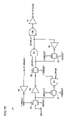
- FIG. 23 is a circuit block diagram which shows the configuration of the internal potential generation circuit 110 of SDRAM in the fifth embodiment according to the present invention, as a comparison to FIG. 7 .
- internal potential generation circuit 110 differs from internal potential generation circuit 50 shown in FIG. 7 in that the output signal VPPON of a VPPL detection circuit 112 instead of output signal VBBON of VBBH detection circuit 52 is inputted into OR gate 56 .
- internal potential generation circuit 110 includes VPPL detection circuit 112 , a VPP detection circuit 113 and a VPP generation circuit 114 .
- VPPL detection circuit 112 sets signal VPPON at “H” level if boosted potential VPP is lower than 3.0 V and sets signal VPPON at “L” level if boosted potential VPP is higher than 3.0 V.
- VPP detection circuit 113 sets signal VPPDET at “H” level if boosted potential VPP is lower than 3.6 V and sets signal VPPDET at “L” level if boosted potential VPP is higher than 3.6 V.
- VPP generation circuit 114 is driven by external power supply potential VDDH, supplies positive charges to a boosted potential VPP line with relatively high charge supply capability if signals VPPON and VPPDET are both at “H” level, supplies positive charges to the boosted potential VPP line with relatively low charge supply capability if signals VPPON and VPPDET are at “L” level and “H” level, respectively, and stops supplying positive charges if signals VPPON and VPPDET are both at “L” level. Since the remaining constitution is equal to that of internal potential generation circuit 50 shown in FIG. 7 , it will not be repeatedly described herein. Although a circuit which generates negative potential VBB is also provided in internal potential generation circuit 110 , it is not shown in the drawing and not described herein.
- FIG. 24 is a time chart which shows the operations of internal potential generation circuit 110 shown in FIG. 23 .
- external power supply potential VDDH is set at 0 V and internal potentials VPP and VDD and signal VPPON are also set at 0 V. If external power supply potential VDDH is applied at certain time, the level of signal VPPON is raised from “L” level to “H” level and VPP generation circuit 114 , standby VDDS generation circuit 55 , active VDDS generation circuit 57 , VBL generation circuit 58 and VCP generation circuit 59 are activated. As a result, boosted potential VPP and internal power supply potential VDDS gradually rise. At this moment, active VDDS generation circuit 57 which is high in charge supply capability and response is activated, so that internal power supply potential VDDS does not greatly change or rock unlike the conventional art.
- active VDDS generation circuit 57 is deactivated. Following this, active VDDS generation circuit 57 is activated only when internal power supply potential VDDS is largely consumed, i.e., only during a period after active command ACT is input and until precharge command PRE is input.
- POR generation circuit 80 and signal generation circuit 81 are added to the configuration of the modification shown in FIG. 25 .
- POR generation circuit 80 and signal generation circuit 81 are the same as those described in the second embodiment.
- Signal generation circuit 81 sets signal STVDCE at “H” level when the level of output signal ZPOR of POR generation circuit 80 is set at “H” level, and sets signal STVDCE at “L” level when the level of output signal VPPDET of VPP detection circuit 113 is set at “L” level.
- Signal STVCE is inputted into OR gate 56 in place of signal VPPDET.
- active VDDS generation circuit 57 is also activated in a period since the level of signal ZPOR is raised to “H” level until boosted potential VPP reaches 3.6 V. It is, therefore, possible to smoothly raise internal power supply potential VDDS.
- filter circuit 101 is added to the configuration of the modification shown in FIG. 26 .
- Filter circuit 101 is the same as that described in the third embodiment.
- Filter circuit 101 is interposed between VPP detection circuit 113 and signal generation circuit 81 . Even if the operation of VPP detection circuit 113 becomes unstable and signal VPPDET changes in a pulse fashion, the output signal VPPDET′ of filter circuit 101 does not change. It is, therefore, possible to prevent a period in which signal STVDCE of signal generation circuit 81 is set at “H” level from being shortened and to prevent internal power supply potential VDD from greatly changing or rocking.
Landscapes
- Engineering & Computer Science (AREA)
- Microelectronics & Electronic Packaging (AREA)
- Computer Hardware Design (AREA)
- Dram (AREA)
Abstract
Description
Claims (10)
Applications Claiming Priority (2)
| Application Number | Priority Date | Filing Date | Title |
|---|---|---|---|
| JP2002-178009 | 2002-06-19 | ||
| JP2002178009A JP2004022117A (en) | 2002-06-19 | 2002-06-19 | Semiconductor device |
Publications (2)
| Publication Number | Publication Date |
|---|---|
| US20030234406A1 US20030234406A1 (en) | 2003-12-25 |
| US7023754B2 true US7023754B2 (en) | 2006-04-04 |
Family
ID=29728184
Family Applications (1)
| Application Number | Title | Priority Date | Filing Date |
|---|---|---|---|
| US10/279,069 Expired - Fee Related US7023754B2 (en) | 2002-06-19 | 2002-10-24 | Semiconductor device having standby mode and active mode |
Country Status (2)
| Country | Link |
|---|---|
| US (1) | US7023754B2 (en) |
| JP (1) | JP2004022117A (en) |
Cited By (5)
| Publication number | Priority date | Publication date | Assignee | Title |
|---|---|---|---|---|
| US20060092745A1 (en) * | 2004-11-04 | 2006-05-04 | Hynix Semiconductor Inc. | Semiconductor memory device with internal power supply |
| US20070183214A1 (en) * | 2006-02-09 | 2007-08-09 | Renesas Technology Corp. | Semiconductor device undergoing defect detection test |
| US20110227552A1 (en) * | 2010-03-16 | 2011-09-22 | Macronix International Co., Ltd. | Apparatus of Supplying Power and Method Therefor |
| US9423814B2 (en) | 2010-03-16 | 2016-08-23 | Macronix International Co., Ltd. | Apparatus of supplying power while maintaining its output power signal and method therefor |
| KR101792737B1 (en) | 2011-12-21 | 2017-11-03 | 에스케이하이닉스 주식회사 | Pumping voltage generator and semiconductor device using the same |
Families Citing this family (2)
| Publication number | Priority date | Publication date | Assignee | Title |
|---|---|---|---|---|
| KR100612944B1 (en) * | 2005-04-29 | 2006-08-14 | 주식회사 하이닉스반도체 | Semiconductor device |
| JP2007226938A (en) * | 2006-01-25 | 2007-09-06 | Citizen Holdings Co Ltd | Nonvolatile semiconductor memory device |
Citations (12)
| Publication number | Priority date | Publication date | Assignee | Title |
|---|---|---|---|---|
| JPH03288218A (en) | 1990-04-03 | 1991-12-18 | Mitsubishi Electric Corp | Semiconductor integrated circuit device |
| JPH0644779A (en) | 1991-08-26 | 1994-02-18 | Nec Corp | Semiconductor dynamic ram device |
| US5337270A (en) | 1991-08-26 | 1994-08-09 | Nec Corporation | Semiconductor dynamic memory |
| US5337284A (en) * | 1993-01-11 | 1994-08-09 | United Memories, Inc. | High voltage generator having a self-timed clock circuit and charge pump, and a method therefor |
| JPH07307443A (en) | 1994-05-15 | 1995-11-21 | Toshiba Micro Comput Eng Corp | Semiconductor device |
| US6313694B1 (en) * | 1998-09-24 | 2001-11-06 | Samsung Electronics Co., Ltd. | Internal power voltage generating circuit having a single drive transistor for stand-by and active modes |
| US6407958B2 (en) * | 1998-05-26 | 2002-06-18 | Mitsubishi Denki Kabushiki Kaisha | Semiconductor integrated circuit device with split hierarchical power supply structure |
| US6429725B1 (en) * | 1998-07-30 | 2002-08-06 | Kabushiki Kaisha Toshiba | Pump circuit with active-mode and stand-by mode booster circuits |
| US6624685B2 (en) * | 1998-09-01 | 2003-09-23 | Texas Instruments Incorporated | Level detection by voltage addition/subtraction |
| US6677804B2 (en) * | 2002-02-11 | 2004-01-13 | Micron Technology, Inc. | Dual bandgap voltage reference system and method for reducing current consumption during a standby mode of operation and for providing reference stability during an active mode of operation |
| US6724242B2 (en) * | 2002-06-07 | 2004-04-20 | Samsung Electronics Co., Ltd. | Pump circuits and methods for integrated circuits including first and second oscillators and first and second pumps |
| US6744687B2 (en) * | 2002-05-13 | 2004-06-01 | Hynix Semiconductor Inc. | Semiconductor memory device with mode register and method for controlling deep power down mode therein |
-
2002
- 2002-06-19 JP JP2002178009A patent/JP2004022117A/en active Pending
- 2002-10-24 US US10/279,069 patent/US7023754B2/en not_active Expired - Fee Related
Patent Citations (12)
| Publication number | Priority date | Publication date | Assignee | Title |
|---|---|---|---|---|
| JPH03288218A (en) | 1990-04-03 | 1991-12-18 | Mitsubishi Electric Corp | Semiconductor integrated circuit device |
| JPH0644779A (en) | 1991-08-26 | 1994-02-18 | Nec Corp | Semiconductor dynamic ram device |
| US5337270A (en) | 1991-08-26 | 1994-08-09 | Nec Corporation | Semiconductor dynamic memory |
| US5337284A (en) * | 1993-01-11 | 1994-08-09 | United Memories, Inc. | High voltage generator having a self-timed clock circuit and charge pump, and a method therefor |
| JPH07307443A (en) | 1994-05-15 | 1995-11-21 | Toshiba Micro Comput Eng Corp | Semiconductor device |
| US6407958B2 (en) * | 1998-05-26 | 2002-06-18 | Mitsubishi Denki Kabushiki Kaisha | Semiconductor integrated circuit device with split hierarchical power supply structure |
| US6429725B1 (en) * | 1998-07-30 | 2002-08-06 | Kabushiki Kaisha Toshiba | Pump circuit with active-mode and stand-by mode booster circuits |
| US6624685B2 (en) * | 1998-09-01 | 2003-09-23 | Texas Instruments Incorporated | Level detection by voltage addition/subtraction |
| US6313694B1 (en) * | 1998-09-24 | 2001-11-06 | Samsung Electronics Co., Ltd. | Internal power voltage generating circuit having a single drive transistor for stand-by and active modes |
| US6677804B2 (en) * | 2002-02-11 | 2004-01-13 | Micron Technology, Inc. | Dual bandgap voltage reference system and method for reducing current consumption during a standby mode of operation and for providing reference stability during an active mode of operation |
| US6744687B2 (en) * | 2002-05-13 | 2004-06-01 | Hynix Semiconductor Inc. | Semiconductor memory device with mode register and method for controlling deep power down mode therein |
| US6724242B2 (en) * | 2002-06-07 | 2004-04-20 | Samsung Electronics Co., Ltd. | Pump circuits and methods for integrated circuits including first and second oscillators and first and second pumps |
Cited By (9)
| Publication number | Priority date | Publication date | Assignee | Title |
|---|---|---|---|---|
| US20060092745A1 (en) * | 2004-11-04 | 2006-05-04 | Hynix Semiconductor Inc. | Semiconductor memory device with internal power supply |
| US7414898B2 (en) * | 2004-11-04 | 2008-08-19 | Hynix Semiconductor, Inc. | Semiconductor memory device with internal power supply |
| US20070183214A1 (en) * | 2006-02-09 | 2007-08-09 | Renesas Technology Corp. | Semiconductor device undergoing defect detection test |
| US7408818B2 (en) * | 2006-02-09 | 2008-08-05 | Renesas Technology Corp. | Semiconductor device undergoing defect detection test |
| US20080298156A1 (en) * | 2006-02-09 | 2008-12-04 | Renesas Technology Corp. | Semiconductor device undergoing defect detection test |
| US20110227552A1 (en) * | 2010-03-16 | 2011-09-22 | Macronix International Co., Ltd. | Apparatus of Supplying Power and Method Therefor |
| US8374007B2 (en) * | 2010-03-16 | 2013-02-12 | Macronix International Co., Ltd. | Supplying power with maintaining its output power signal with the assistance of another power apply and method therefor |
| US9423814B2 (en) | 2010-03-16 | 2016-08-23 | Macronix International Co., Ltd. | Apparatus of supplying power while maintaining its output power signal and method therefor |
| KR101792737B1 (en) | 2011-12-21 | 2017-11-03 | 에스케이하이닉스 주식회사 | Pumping voltage generator and semiconductor device using the same |
Also Published As
| Publication number | Publication date |
|---|---|
| JP2004022117A (en) | 2004-01-22 |
| US20030234406A1 (en) | 2003-12-25 |
Similar Documents
| Publication | Publication Date | Title |
|---|---|---|
| US10998033B2 (en) | Semiconductor memory device and operating method thereof | |
| US8737155B2 (en) | Power saving memory apparatus, systems, and methods | |
| US7626883B2 (en) | Semiconductor memory device | |
| JP3704188B2 (en) | Semiconductor memory device | |
| US6426908B1 (en) | Semiconductor memory device with reduced current consumption in data hold mode | |
| US8441840B2 (en) | Semiconductor device and data processing system | |
| US11495284B2 (en) | Memory device including bitline sense amplifier and operating method thereof | |
| US8638630B2 (en) | Semiconductor device having hierarchical bit line structure | |
| US6052324A (en) | Semiconductor memory device capable of fast sensing operation | |
| US6236605B1 (en) | Semiconductor integrated circuit and semiconductor memory device including overdriving sense amplifier | |
| JPH10135424A (en) | Semiconductor integrated circuit device | |
| JP3782227B2 (en) | Semiconductor memory device | |
| US7911863B2 (en) | Semiconductor device and DRAM controller | |
| JP2001256781A (en) | Semiconductor storage device | |
| JP4260469B2 (en) | Semiconductor memory device | |
| US20100020623A1 (en) | Circuit and method of generating voltage of semiconductor memory apparatus | |
| US7023754B2 (en) | Semiconductor device having standby mode and active mode | |
| US6330173B1 (en) | Semiconductor integrated circuit comprising step-up voltage generation circuit | |
| US6614270B2 (en) | Potential detecting circuit having wide operating margin and semiconductor device including the same | |
| KR100438237B1 (en) | Semiconductor integrated circuit having test circuit | |
| US20080205120A1 (en) | Multiple layer random accessing memory | |
| US6469952B1 (en) | Semiconductor memory device capable of reducing power supply voltage in a DRAM's word driver | |
| JP5135608B2 (en) | Semiconductor memory device | |
| CN101075476B (en) | Semiconductor memory device and driving method thereof | |
| JPH09320266A (en) | Dynamic random access memory |
Legal Events
| Date | Code | Title | Description |
|---|---|---|---|
| AS | Assignment |
Owner name: MITSUBISHI ELECTRIC ENGINEERING COMPANY LIMITED, J Free format text: ASSIGNMENT OF ASSIGNORS INTEREST;ASSIGNORS:AKIYAMA, MIHOKO;MORISHITA, FUKASHI;REEL/FRAME:013432/0023 Effective date: 20020925 Owner name: MITSUBISHI DENKI KABUSHIKI KAISHA, JAPAN Free format text: ASSIGNMENT OF ASSIGNORS INTEREST;ASSIGNORS:AKIYAMA, MIHOKO;MORISHITA, FUKASHI;REEL/FRAME:013432/0023 Effective date: 20020925 |
|
| AS | Assignment |
Owner name: MITSUBISHI DENKI KABUSHIKI KAISHA, JAPAN Free format text: CORRECTIVE ASSIGNMENT CORRECT THE ADDRESS OF THE SECOND ASSIGNEE. PREVIOUSLY RECORDED ON REEL 013432 FRAME 0023;ASSIGNORS:AKIYAMA, MIHOKO;MORISHITA, FUKASHI;REEL/FRAME:013800/0926 Effective date: 20020925 Owner name: MITSUBISHI ELECTRIC ENGINEERING COMPANY LIMITED, J Free format text: CORRECTIVE ASSIGNMENT CORRECT THE ADDRESS OF THE SECOND ASSIGNEE. PREVIOUSLY RECORDED ON REEL 013432 FRAME 0023;ASSIGNORS:AKIYAMA, MIHOKO;MORISHITA, FUKASHI;REEL/FRAME:013800/0926 Effective date: 20020925 |
|
| AS | Assignment |
Owner name: RENESAS TECHNOLOGY CORP., JAPAN Free format text: ASSIGNMENT OF ASSIGNORS INTEREST;ASSIGNOR:MITSUBISHI DENKI KABUSHIKI KAISHA;REEL/FRAME:014502/0289 Effective date: 20030908 |
|
| AS | Assignment |
Owner name: RENESAS TECHNOLOGY CORP., JAPAN Free format text: ASSIGNMENT OF ASSIGNORS INTEREST;ASSIGNOR:MITSUBISHI DENKI KABUSHIKI KAISHA;REEL/FRAME:015185/0122 Effective date: 20030908 |
|
| FEPP | Fee payment procedure |
Free format text: PAYOR NUMBER ASSIGNED (ORIGINAL EVENT CODE: ASPN); ENTITY STATUS OF PATENT OWNER: LARGE ENTITY |
|
| REMI | Maintenance fee reminder mailed | ||
| LAPS | Lapse for failure to pay maintenance fees | ||
| STCH | Information on status: patent discontinuation |
Free format text: PATENT EXPIRED DUE TO NONPAYMENT OF MAINTENANCE FEES UNDER 37 CFR 1.362 |
|
| FP | Lapsed due to failure to pay maintenance fee |
Effective date: 20100404 |
|
| AS | Assignment |
Owner name: RENESAS ELECTRONICS CORPORATION, JAPAN Free format text: CHANGE OF NAME;ASSIGNOR:RENESAS TECHNOLOGY CORPORATION;REEL/FRAME:043390/0117 Effective date: 20100416 Owner name: RENESAS SYSTEM DESIGN CO., LTD., JAPAN Free format text: ASSIGNMENT OF ASSIGNORS INTEREST;ASSIGNOR:MITSUBISHI ELECTRIC ENGINEERING CO., LTD.;REEL/FRAME:043668/0291 Effective date: 20170626 |
|
| AS | Assignment |
Owner name: RENESAS ELECTRONICS CORPORATION, JAPAN Free format text: CHANGE OF ADDRESS;ASSIGNOR:RENESAS ELECTRONICS CORPORATION;REEL/FRAME:044512/0218 Effective date: 20150727 Owner name: RENESAS ELECTRONICS CORPORATION, JAPAN Free format text: MERGER;ASSIGNOR:RENESAS SYSTEM DESIGN CO., LTD.;REEL/FRAME:044921/0873 Effective date: 20170701 |