US7017993B2 - Seat device - Google Patents
Seat device Download PDFInfo
- Publication number
- US7017993B2 US7017993B2 US10/326,411 US32641102A US7017993B2 US 7017993 B2 US7017993 B2 US 7017993B2 US 32641102 A US32641102 A US 32641102A US 7017993 B2 US7017993 B2 US 7017993B2
- Authority
- US
- United States
- Prior art keywords
- turning
- seat device
- rail
- link member
- upper rail
- Prior art date
- Legal status (The legal status is an assumption and is not a legal conclusion. Google has not performed a legal analysis and makes no representation as to the accuracy of the status listed.)
- Expired - Lifetime
Links
- 230000007246 mechanism Effects 0.000 claims abstract description 28
- 230000000149 penetrating effect Effects 0.000 claims description 4
- 230000000694 effects Effects 0.000 claims 3
- 238000005516 engineering process Methods 0.000 description 2
- 230000005540 biological transmission Effects 0.000 description 1
- 239000002184 metal Substances 0.000 description 1
- 238000000034 method Methods 0.000 description 1
Images


Classifications
-
- B—PERFORMING OPERATIONS; TRANSPORTING
- B60—VEHICLES IN GENERAL
- B60N—SEATS SPECIALLY ADAPTED FOR VEHICLES; VEHICLE PASSENGER ACCOMMODATION NOT OTHERWISE PROVIDED FOR
- B60N2/00—Seats specially adapted for vehicles; Arrangement or mounting of seats in vehicles
- B60N2/02—Seats specially adapted for vehicles; Arrangement or mounting of seats in vehicles the seat or part thereof being movable, e.g. adjustable
- B60N2/20—Seats specially adapted for vehicles; Arrangement or mounting of seats in vehicles the seat or part thereof being movable, e.g. adjustable the back-rest being tiltable, e.g. to permit easy access
-
- B—PERFORMING OPERATIONS; TRANSPORTING
- B60—VEHICLES IN GENERAL
- B60N—SEATS SPECIALLY ADAPTED FOR VEHICLES; VEHICLE PASSENGER ACCOMMODATION NOT OTHERWISE PROVIDED FOR
- B60N2/00—Seats specially adapted for vehicles; Arrangement or mounting of seats in vehicles
- B60N2/02—Seats specially adapted for vehicles; Arrangement or mounting of seats in vehicles the seat or part thereof being movable, e.g. adjustable
- B60N2/04—Seats specially adapted for vehicles; Arrangement or mounting of seats in vehicles the seat or part thereof being movable, e.g. adjustable the whole seat being movable
- B60N2/06—Seats specially adapted for vehicles; Arrangement or mounting of seats in vehicles the seat or part thereof being movable, e.g. adjustable the whole seat being movable slidable
- B60N2/07—Slide construction
- B60N2/0702—Slide construction characterised by its cross-section
- B60N2/0705—Slide construction characterised by its cross-section omega-shaped
-
- B—PERFORMING OPERATIONS; TRANSPORTING
- B60—VEHICLES IN GENERAL
- B60N—SEATS SPECIALLY ADAPTED FOR VEHICLES; VEHICLE PASSENGER ACCOMMODATION NOT OTHERWISE PROVIDED FOR
- B60N2/00—Seats specially adapted for vehicles; Arrangement or mounting of seats in vehicles
- B60N2/02—Seats specially adapted for vehicles; Arrangement or mounting of seats in vehicles the seat or part thereof being movable, e.g. adjustable
- B60N2/04—Seats specially adapted for vehicles; Arrangement or mounting of seats in vehicles the seat or part thereof being movable, e.g. adjustable the whole seat being movable
- B60N2/06—Seats specially adapted for vehicles; Arrangement or mounting of seats in vehicles the seat or part thereof being movable, e.g. adjustable the whole seat being movable slidable
- B60N2/07—Slide construction
- B60N2/0702—Slide construction characterised by its cross-section
- B60N2/0715—C or U-shaped
-
- B—PERFORMING OPERATIONS; TRANSPORTING
- B60—VEHICLES IN GENERAL
- B60N—SEATS SPECIALLY ADAPTED FOR VEHICLES; VEHICLE PASSENGER ACCOMMODATION NOT OTHERWISE PROVIDED FOR
- B60N2/00—Seats specially adapted for vehicles; Arrangement or mounting of seats in vehicles
- B60N2/02—Seats specially adapted for vehicles; Arrangement or mounting of seats in vehicles the seat or part thereof being movable, e.g. adjustable
- B60N2/04—Seats specially adapted for vehicles; Arrangement or mounting of seats in vehicles the seat or part thereof being movable, e.g. adjustable the whole seat being movable
- B60N2/06—Seats specially adapted for vehicles; Arrangement or mounting of seats in vehicles the seat or part thereof being movable, e.g. adjustable the whole seat being movable slidable
- B60N2/08—Seats specially adapted for vehicles; Arrangement or mounting of seats in vehicles the seat or part thereof being movable, e.g. adjustable the whole seat being movable slidable characterised by the locking device
- B60N2/0812—Location of the latch
- B60N2/0825—Location of the latch outside the rail
-
- B—PERFORMING OPERATIONS; TRANSPORTING
- B60—VEHICLES IN GENERAL
- B60N—SEATS SPECIALLY ADAPTED FOR VEHICLES; VEHICLE PASSENGER ACCOMMODATION NOT OTHERWISE PROVIDED FOR
- B60N2/00—Seats specially adapted for vehicles; Arrangement or mounting of seats in vehicles
- B60N2/02—Seats specially adapted for vehicles; Arrangement or mounting of seats in vehicles the seat or part thereof being movable, e.g. adjustable
- B60N2/04—Seats specially adapted for vehicles; Arrangement or mounting of seats in vehicles the seat or part thereof being movable, e.g. adjustable the whole seat being movable
- B60N2/06—Seats specially adapted for vehicles; Arrangement or mounting of seats in vehicles the seat or part thereof being movable, e.g. adjustable the whole seat being movable slidable
- B60N2/08—Seats specially adapted for vehicles; Arrangement or mounting of seats in vehicles the seat or part thereof being movable, e.g. adjustable the whole seat being movable slidable characterised by the locking device
- B60N2/0831—Movement of the latch
- B60N2/0837—Movement of the latch pivoting
- B60N2/085—Movement of the latch pivoting about a transversal axis
-
- B—PERFORMING OPERATIONS; TRANSPORTING
- B60—VEHICLES IN GENERAL
- B60N—SEATS SPECIALLY ADAPTED FOR VEHICLES; VEHICLE PASSENGER ACCOMMODATION NOT OTHERWISE PROVIDED FOR
- B60N2/00—Seats specially adapted for vehicles; Arrangement or mounting of seats in vehicles
- B60N2/02—Seats specially adapted for vehicles; Arrangement or mounting of seats in vehicles the seat or part thereof being movable, e.g. adjustable
- B60N2/04—Seats specially adapted for vehicles; Arrangement or mounting of seats in vehicles the seat or part thereof being movable, e.g. adjustable the whole seat being movable
- B60N2/12—Seats specially adapted for vehicles; Arrangement or mounting of seats in vehicles the seat or part thereof being movable, e.g. adjustable the whole seat being movable slidable and tiltable
Definitions
- This invention generally relates to a vehicle seat device equipping a walk in mechanism.
- a vehicle is equipped with a walk in mechanism for moving a front seat in forward direction in order to make the passenger easily entry on or off the rear seat of the vehicle by releasing a locking mechanism of a seat slide device, when the seatback (a back seat of the front seat) turns in forward direction.
- FIG. 2001-63410 An example of a seat device equipping a walk in mechanism is disclosed in a Japanese Patent Laid-Open Publication No. 2001-63410.
- This disclosed seat device has an upper rail being capable of sliding freely on a lower rail fixed to a vehicle floor in forward and backward directions.
- This seat device has a lock/unlock mechanism and usually maintains the seat device in a locking condition by fixing the upper and lower rails each other.
- the lock/unlock mechanism includes a side tooth (or a nail) of an operational handle supported in the upper rail side portion. The side tooth can engage with or disengage from a window provided in the lower rail. When the walk in mechanism is operated, the operational handle is moved and the side tooth is disengaged from the window, then the upper rail is made slidable on the lower rail in forward and backward directions.
- a supporting bracket is fixed to a top surface of an upper rail.
- a moving member is displaced to be capable of sliding in forward and backward directions relative to the supporting bracket.
- the moving member is maintained in the original position by a spring force.
- the moving member is connected to the seatback of the front seat by a cable.
- the walk in mechanism of the prior technology is provided with a memory mechanism including a finger member and a hook member installed on the moving member.
- the hook member engages with a hole formed on a plate fixed on the upper rail and maintains the moving member to disengage the side tooth from the window.
- the engagement of the hook member with the upper rail is released by the operation of the finger member.
- the moving member is permitted to slide in forward direction and leaves from the operational handle to disengage the side tooth from the window of the lower rail. Then the lock condition between the upper rail and lower rail is also restored in the original position.
- the hook device is pivotally supported on the moving member and to the upper rail, and engages with or disengages from the hole formed on the plate.
- the hook device For the smooth slide of the moving member on the upper rail, rather loose engagement between the moving member and the upper rail is required. This loose engagement, however, makes the hook position be unstable relative to the hole. This unstable engagement of the hook member to the hole of the metal plate may cause unstable position restoring operation.
- the movement of the moving member of the walk in mechanism on the one side of the seat device is transmitted to a latch member of the walk in mechanism on another side of the seat device by a connecting rod and long holes formed in levers attached on the both ends of the rod.
- the long holes engage with pins fixed on the moving members on the both side seat device.
- the object of the present invention is to solve a disadvantageous point of the conventional technology described in the foregoing.
- the present invention provides a seat device having a lock/unlock mechanism for releasing a locking condition between a lower rail and an upper rail by turning down a seatback in forward direction and allowing said upper rail to slide on said lower rail, comprising: a turning bracket of said lock/unlock mechanism rotatably supported on a lower arm fixed to said upper rail; an actuating lever turning together with said turning bracket; and a lock segment inserted into opening portions of both rails in accordance with movement of said actuating lever, wherein said seatback turning down in said forward direction causes to turn said turning bracket and said actuating, lever in one direction and release a locking condition of said both rails.
- the turning bracket is turned in conjunction with the seatback turning down in forward direction and locking engagement between the upper rail and the lower rails released.
- movements of each members are transmitted only by a rotational movement. That is, to say, since there is no sliding engagement of the members on the upper rail which requires loose engagement, or gaps between the members. Therefore, unstable cooperation of the both of walk in mechanisms can be avoided, and this achieves exact position restoring operation.
- FIG. 1 is an exploded view of a locking mechanism of both rails as an example of the present invention
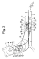
- FIG. 2 is a side view of a regular case of a seat
- FIG. 3 to a side view of a case that a setback is turned down in forward direction due to a walk in operation
- FIG. 4 is a side view of a case that a detector member gets in contact with a detector plate while the seat moves in forward direction;
- FIG. 5 is a side view of a case that the seat moves to the furthest position in forward direction
- FIG. 6 is a side view of a case that the detector member gets in contact with the detector plate while the seat is moved in the backward direction so as to restore the seat to the predetermined position.
- FIG. 7 is a side view of a case that the seat is moved in the backward direction due to a reverse walk in operation
- FIG. 8 is a cross sectional view of a mechanism of locking an upper rail in a lower rail
- FIG. 9 is a front view of a case that a hook member and the detector member are assembled together.
- FIG. 10 is a top plane view of FIG. 9 .
- FIGS. 1 and 2 First, one example of the present invention is explained with reference to FIGS. 1 and 2 .
- An upper rail 2 is installed in a sliding way in forward and backward directions of a lower rail 1 adapted to be fixed on a vehicle floor.
- a lower arm 3 is fixed to the upper rail 2 .
- An upper arm attached on the side of a seatback is assembled with the lower arm 3 attached on the side of a seat cushion in a reclining way in forward and backward directions by a pin 5 .
- a turning member 6 which turns together with the upper arm 4 , is fixed to the upper arm 4 .
- the turning member 6 is made of a plate having a nearly rectangular shape, and a free end portion 7 projects from a circumferential surface 8 of the upper arm 4 .
- the first link member 10 has a shape of “L,” and rotatably connected to the lower arm 3 by a pin 9 .
- a contact pin 11 is fixed to one end of the first link member 10 and a pin 12 is fixed to another end of the first link member 10 .
- the second link member 13 having a nearly sector shape is rotatably connected to the lower arm 3 by the pin 9 .
- the second link member 13 is provided with a long hole 14 for receiving the pin 12 of the first link member 10 and supports one end of a cable 15 .
- the contact pin 11 is positioned in the left side ( FIG. 2 ) of the free end portion 7 of the turning member 6
- the pin 12 is positioned in the right end corner ( FIG. 2 ) of the long hole 14 .
- Both of the link members 10 and 13 are biased in counterclockwise directions of FIG. 2 by a spring (not illustrated).
- One end of the cable 15 is supported by a frame 16 , which has a “C” shaped cross section and is fixed on the front end portion of the lower arm 3 .
- a turning bracket 18 as a member of a lock/unlock mechanism is fixed to an end of a turning pin 17 penetrating the frame 16 .
- An actuating lever 20 which has a shape of “L” receives an biasing force of a spring 19 , and is fixed to another end of the turning pin 17 .
- the cable 15 is connected to a leg segment 21 of the turning bracket 18 . In this way, if the cable 15 is pulled, the actuating lever 20 is turned together with the turning bracket 18 in clockwise direction (in FIG. 1 ).
- the hook member 22 has a projecting portion 25 and a mounting portion 26 and a detecting member 29 is connected to the mounting portion 26 in a turning way by a pin 27 and a spring 28 .
- a latch segment 30 is provided on the top end portion of the detecting member 29 as to press on the side surface of the hook member 22 .
- FIGS. 9 and 10 illustrate an assembly of the hook member 22 and the detecting member 29 .
- One end of the spring 28 which is wound around the pin 27 is hooked on the latch segment 30 and another end of the spring 28 is mounted on the mounting portion 26 .
- the latch segment 30 is lifted and turned from the mounting portion 26 when the detecting member 29 turns in arrow A direction ( FIG. 9 ), and the hook member 22 is turned around the pin 23 (refer to FIG. 1 ) in the clockwise direction together with the detecting member 29 when the detecting member 29 turns in arrow B direction.
- the projecting portion 25 of the, hook member 22 can be seated on a notch portion 31 of the turning bracket 18 . Further, the side surface of the projecting portion 25 can contact on the side surface of a latch segment 32 which includes the notch portion 31 .
- the lower end portion of the actuating lever 20 is inserted into the inside portion from an opening 33 of formed in an upper surface of the upper rail 2 .
- a pair of detecting plates 34 and 35 spatially separated with each other is fixed to the side surface of the lower rail 1 .
- the free end portion of the detecting member 29 can touch and slide on the detecting plates 34 and 35 .
- a connecting rod 43 is connected to a turning bracket 18 and can turn together with the turning bracket 18 .
- the connecting rod 43 transmits the rotation of the turning bracket 18 to a lock/unlock mechanism (the same mechanism as the mechanism of FIGS. 1 and 8 ) installed on the other side of the seat for locking or unlocking between the upper rail 2 and the lower rail 3 .
- the lower rail 1 has an “U” shaped cross section and the upper rail 2 has a reversed “U,” shaped section.
- windows 36 and 37 are formed in opposed wall portions of the both lower and upper rails 1 , 2 , and lock segments 39 of lock levers 38 are inserted into the windows 36 and 37 (a locking condition of both lower and upper rails 1 , 2 ).
- the lock lever 38 has a contact segment 40 and this contact segment 40 is opposed to the end portion of the actuating lever 20 via an end portion of a loop handle 41 .
- the loop handle 41 has “U” shaped cross section for receiving the contact of the actuating lever 20 , and the lower surface of the “U” shaped portion can contact on the segment 40 .
- the contact segment 40 is a plate for receiving a force from the actuating lever 20 via the loop handle 41 .
- the lock lever 38 is rotatably connected to a lever center 42 mounted on the upper rail 2 .
- the lock lever 38 is usually situated by spring force (the spring is not shown),in the locking position indicated by solid lines in FIG. 8 .
- FIG. 2 illustrates the seat situated in a seating position.
- the turning bracket 18 , the turning pin 17 , and the actuating lever 20 are at the positions which are corresponding to positions shown by the solid line in FIG. 8 , and both rails 1 and 2 are maintained in the locked condition.
- FIG. 3 shows the situation of the seatback turned down in front direction for walk in operation.
- the free end portion 7 of the turning member 6 turns the first link member 10 around the pin 9 by contacting on the contact pin 11 to counterclockwise direction with the seatback down rotation in forward direction. Accordingly, the pin 12 pushes the end portion of the long hole 14 and turns the second link member 13 in the counterclockwise direction.
- the actuating lever 20 is turned in clockwise direction via the turning pin 17 in the clockwise direction.
- the lock lever 38 is moved to the position shown by two dot lines in FIG. 8 from the solid lines position by the loop handle 41 , and the lock segment 39 is disengaged from the windows 36 and 37 and both rails 1 and 2 are set in the unlocking condition.
- the projecting portion 25 of the hook member 22 engages with the notch portion 31 of the turning bracket 18 by turning the turning bracket 18 in the clockwise direction, the rotation of the turning bracket 18 is prevented by the hook member 22 , and the turning bracket 18 is maintained in the position shown in FIG. 3 , and the both upper and lower rails 1 and 2 are kept in the unlocking condition.
- the seat is possible to move in forward direction.
- FIG. 4 illustrates the situation that the detecting member 29 gets in contact with the detecting plate 34 during the seat is moved in forward direction.
- the detecting member 29 is turned around the pin 27 in the clockwise direction by the detecting member 29 , but only the latch segment 30 moves to leave from the hook member 22 and the engagement of the projecting portion 25 on the notch portion 31 is kept, that is to say, the both upper and lower rails 1 and 2 are kept in the unlocking condition.
- FIG. 5 shows that the seat is moved to the front most position, that is to say, in this situation the walk in operation has been completed.
- FIG. 6 shows that after the walk in operation is completed, the seat is moved backward.
- the detecting member 29 gets in contact with the detecting plate 34 , the detecting member 29 turns in counterclockwise direction.
- the hook member 22 is pushed and turned by the latch segment 30 , and the hook member 22 is turned in counterclockwise direction together with the detecting member 29 . Accordingly, the projecting portion 25 is disengaged from the notch portion 31 and the turning bracket 18 is turned in counterclockwise direction by the force of the spring 19 .
- the turning bracket 18 turns in counterclockwise direction with the actuating lever 20 , then the lock lever 38 is moved back to the position of the solid lines in FIG. 8 , the lock segment 39 is inserted into the windows 36 and 37 as illustrated in FIG. 2 and FIG. 8 , and both rails 1 and 2 are set in locking condition.
- FIG. 7 illustrates a reverse walk in operation.
- the seat on the second line is moved to be closely adjacent to the seat on the third line, the seatback is turned down in forward direction and the locking condition is released, the seat on the second line is moved toward to the seat on the third.
- This operation is so called reverse walk in and is explained with reference to FIG. 7 .
- the seatback is turned down in forward direction and then the unlocking condition between the rails 1 and 2 is obtained as illustrated in FIG. 3 . Then, if the seat is moved in the backward direction as illustrated in FIG. 7 , the detecting member 29 gets in contact with the detecting plate 35 , the detecting member 29 is turned in the counterclockwise direction, and then the hook member 22 is turned in the same direction as the detecting member 29 . Then, the projecting portion 25 is disengaged from the notch portion 31 (in the same way as the case of FIG. 6 ). Accordingly, since the turning bracket 18 and the actuating lever 20 are turned in the counterclockwise direction and the seat is moved in the backward direction, both rails 1 and 2 are set to be the locking condition at the predetermined position.
- the second line seat is moved not to have clearance with the seat on the third line, and maintained in the locking condition.
- the operation for restoring to the position for seating as shown in FIG. 2 from the locking condition shown in FIG. 7 is performed by raising the seatback up and releasing the locking condition by operating the loop handle 41 .
- the seatback is turned down in forward direction without raising up the seatback, if the loop handle 41 is operated, the condition of FIG. 3 is obtained and then it becomes possible to move the seat at the time of releasing the lock.
Landscapes
- Engineering & Computer Science (AREA)
- Aviation & Aerospace Engineering (AREA)
- Transportation (AREA)
- Mechanical Engineering (AREA)
- Seats For Vehicles (AREA)
Abstract
Description
Claims (19)
Applications Claiming Priority (2)
| Application Number | Priority Date | Filing Date | Title |
|---|---|---|---|
| JP2001391878A JP2003182415A (en) | 2001-12-25 | 2001-12-25 | Seat device |
| JP2001-391878 | 2001-12-25 |
Publications (2)
| Publication Number | Publication Date |
|---|---|
| US20030122412A1 US20030122412A1 (en) | 2003-07-03 |
| US7017993B2 true US7017993B2 (en) | 2006-03-28 |
Family
ID=19188569
Family Applications (1)
| Application Number | Title | Priority Date | Filing Date |
|---|---|---|---|
| US10/326,411 Expired - Lifetime US7017993B2 (en) | 2001-12-25 | 2002-12-23 | Seat device |
Country Status (4)
| Country | Link |
|---|---|
| US (1) | US7017993B2 (en) |
| JP (1) | JP2003182415A (en) |
| DE (1) | DE10260826B4 (en) |
| FR (1) | FR2833896B1 (en) |
Cited By (13)
| Publication number | Priority date | Publication date | Assignee | Title |
|---|---|---|---|---|
| US20060138843A1 (en) * | 2004-12-23 | 2006-06-29 | Burkhard Becker | Forwardly movable vehicle seat with an underframe and two pairs of rails |
| US20080106135A1 (en) * | 2006-11-07 | 2008-05-08 | Hyundai Motor Company | Recliner regulating structure of rear seat for vehicle |
| US20080143160A1 (en) * | 2004-10-08 | 2008-06-19 | Johnson Controls Gmbh | Device for Limiting the Adjustability of a Vehicle Seat |
| US20100102610A1 (en) * | 2004-12-15 | 2010-04-29 | Johnson Controls Technology Company | Track release mechanism |
| US20100176265A1 (en) * | 2007-03-29 | 2010-07-15 | Aisin Seiki Kabushiki Kaisha | Seat slide device for vehicle |
| US20110127822A1 (en) * | 2009-11-30 | 2011-06-02 | Toyota Motor Engineering & Manufacturing North America, Inc. | Seat assembly having rear actuated egress mechanism |
| US20110127818A1 (en) * | 2009-12-01 | 2011-06-02 | Toyota Motor Engineering & Manufacturing | Seat assembly having dual actuated locking mechanism |
| US8757722B2 (en) | 2011-08-16 | 2014-06-24 | Magna Seating Inc | Seat assembly with easy-entry mechanism and fold flat feature |
| US20140183920A1 (en) * | 2012-12-31 | 2014-07-03 | Ts Tech Co., Ltd. | Vehicle seat |
| US9254761B1 (en) * | 2014-07-16 | 2016-02-09 | Ford Global Technologies, Llc | Over-travel mechanism for easy-entry system |
| US9586502B2 (en) | 2014-03-25 | 2017-03-07 | Aisin Seiki Kabushiki Kaisha | Seat apparatus |
| US20190381913A1 (en) * | 2018-06-19 | 2019-12-19 | Tesla, Inc. | Electronically controlled seat system with tilt-and-slide mode |
| US20230045201A1 (en) * | 2021-07-28 | 2023-02-09 | Hyundai Motor Company | Device for reclining seatback for vehicle |
Families Citing this family (32)
| Publication number | Priority date | Publication date | Assignee | Title |
|---|---|---|---|---|
| DE10151762B4 (en) * | 2001-10-19 | 2007-08-16 | C. Rob. Hammerstein Gmbh & Co. Kg | Predisplaceable motor vehicle seat with access to a rear seat through a front door |
| JP2004058928A (en) * | 2002-07-31 | 2004-02-26 | Fuji Kiko Co Ltd | Vehicle seat folding mechanism |
| JP4103524B2 (en) * | 2002-09-30 | 2008-06-18 | アイシン精機株式会社 | Walk-in device for vehicle seat |
| JP4151366B2 (en) * | 2002-09-30 | 2008-09-17 | アイシン精機株式会社 | Walk-in device for vehicle seat |
| FR2851209B1 (en) * | 2003-02-19 | 2006-09-29 | Faurecia Sieges Automobile | SLIDER FOR A SEAT OF A MOTOR VEHICLE AND A SEAT WITH SUCH A SLIDER |
| DE102005039540B4 (en) * | 2005-02-11 | 2018-02-08 | Adient Luxembourg Holding S.à.r.l. | Retractable vehicle seat with a base frame and a folding backrest |
| FR2902713B1 (en) * | 2006-06-21 | 2008-09-05 | Faurecia Sieges Automobile | DEVICE FOR LOCKING A LATCH SLIDER OF A SEAT |
| WO2008019033A1 (en) * | 2006-08-03 | 2008-02-14 | Johnson Controls Technology Company | Recliner mechanism |
| US8066327B2 (en) * | 2006-08-22 | 2011-11-29 | Grand Rapids Controls Company Llc | Control mechanism |
| JP5119911B2 (en) * | 2007-12-26 | 2013-01-16 | トヨタ紡織株式会社 | Vehicle seat |
| JP4505028B2 (en) * | 2008-06-09 | 2010-07-14 | トヨタ自動車株式会社 | Sheet |
| JP5181866B2 (en) * | 2008-06-24 | 2013-04-10 | トヨタ紡織株式会社 | Vehicle seat switching mechanism |
| JP5275768B2 (en) * | 2008-12-03 | 2013-08-28 | デルタ工業株式会社 | Sheet device |
| WO2011063521A1 (en) * | 2009-11-26 | 2011-06-03 | Magna Seating Inc. | Seat track easy-entry actuation mechanism |
| US8585145B2 (en) * | 2011-01-14 | 2013-11-19 | Lear Corporation | Vehicle seat easy entry system |
| FR2973748B1 (en) * | 2011-04-07 | 2013-05-10 | Renault Sas | AUTOMOBILE SEAT EQUIPPED WITH A RE-RECALL MEANS |
| DE102012011507A1 (en) * | 2012-06-09 | 2013-12-12 | GM Global Technology Operations LLC (n. d. Gesetzen des Staates Delaware) | Vehicle seat, vehicle and method for this |
| DE102013004342B4 (en) * | 2012-12-28 | 2018-11-22 | Adient Luxembourg Holding S.À R.L. | seat adjustment |
| CN103264646B (en) * | 2013-06-26 | 2016-05-04 | 长城汽车股份有限公司 | Can turn down the seat tripper with slippage |
| DE102014220474B4 (en) * | 2014-07-03 | 2023-03-30 | Adient Us Llc | Backrest adjuster for a seat and vehicle seat |
| CN104512281B (en) * | 2014-12-25 | 2016-08-17 | 上海延锋江森座椅有限公司 | A kind of mechanism falling backrest and unlocking seat slide simultaneously |
| JP6398836B2 (en) * | 2015-03-30 | 2018-10-03 | アイシン精機株式会社 | Vehicle seat device |
| DE102015009357B4 (en) | 2015-07-24 | 2019-01-31 | Faurecia Autositze Gmbh | Vehicle seat with easy-entry adjustment |
| JP2017047728A (en) * | 2015-08-31 | 2017-03-09 | アイシン精機株式会社 | Vehicle seat walk-in device |
| JP6270072B2 (en) * | 2016-03-01 | 2018-01-31 | トヨタ車体株式会社 | Vehicle seat |
| JP6347491B2 (en) * | 2016-03-01 | 2018-06-27 | トヨタ車体株式会社 | Vehicle seat |
| JP2018144694A (en) | 2017-03-07 | 2018-09-20 | トヨタ紡織株式会社 | Slide device |
| US10308146B1 (en) * | 2018-01-25 | 2019-06-04 | Ford Global Technologies, Llc | Track release mechanism for a seating assembly |
| JP2020032787A (en) * | 2018-08-28 | 2020-03-05 | シロキ工業株式会社 | Vehicle seat slide device |
| CN109435793A (en) * | 2018-09-29 | 2019-03-08 | 延锋安道拓座椅有限公司 | A kind of unlocking mechanism convenient for rear passenger disengaging |
| JP7361676B2 (en) * | 2020-11-30 | 2023-10-16 | コイト電工株式会社 | seat equipment |
| CN117052251B (en) * | 2023-10-13 | 2024-01-05 | 广东图特精密五金科技股份有限公司 | Sliding door structure with locking function |
Citations (13)
| Publication number | Priority date | Publication date | Assignee | Title |
|---|---|---|---|---|
| US5352019A (en) | 1993-06-18 | 1994-10-04 | Firma C. Rob. Hammerstein Gmbh | Motor vehicle seat movable in the longitudinal direction in the tipped state |
| US5605377A (en) * | 1995-09-27 | 1997-02-25 | Atoma International Inc. | Vehicle seat with full memory easy entry |
| US5855413A (en) * | 1996-12-03 | 1999-01-05 | Bertrand Faure Equipments Sa | Slideway for a vehicle seat, and a seat including such a slideway |
| US5882074A (en) * | 1996-07-31 | 1999-03-16 | Aisin Seiki Kabushiki Kaisha | Walk-in apparatus for a vehicle seat |
| US6048030A (en) * | 1997-05-13 | 2000-04-11 | Fujikoko Kabushiki Kaisha | Seat sliding apparatus |
| FR2787749A1 (en) | 1998-12-25 | 2000-06-30 | Aisin Seiki | SLIDING DEVICE FOR VEHICLE SEAT |
| US6098946A (en) * | 1998-05-12 | 2000-08-08 | Bertrand Faure Equipements Sa | Slide rail for a vehicle seat with longitudinal setting memory and seat comprising such a slide rail |
| FR2797234A1 (en) | 1999-08-02 | 2001-02-09 | Faure Bertrand Equipements Sa | Slide mechanism, for vehicle seats, has bolt with control mechanism and locking mechanism, which is retained in position by anchorage mechanism, with independent operating finger |
| DE10020923A1 (en) | 2000-04-28 | 2001-12-13 | Hammerstein Gmbh C Rob | Forward folding vehicle front seat is supported on underframe having forward folding swing bar to move seat support independently of position of seat adjuster device |
| US6336679B1 (en) * | 1998-01-28 | 2002-01-08 | Bertrand Faure Components Ltd. | Rotary recliner control mechanism for multifunction vehicle seat applications |
| DE10136244C1 (en) | 2001-07-25 | 2002-08-29 | Keiper Gmbh & Co | Vehicle seat, in particular motor vehicle seat |
| US6478358B1 (en) | 1998-12-18 | 2002-11-12 | Aisin Seiki Kabushiki Kaisha | Seat device for a vehicle |
| US6641218B2 (en) * | 2001-02-08 | 2003-11-04 | Nhk Spring Co., Ltd | Seat apparatus for automobile |
Family Cites Families (4)
| Publication number | Priority date | Publication date | Assignee | Title |
|---|---|---|---|---|
| JP3686116B2 (en) * | 1995-03-22 | 2005-08-24 | シロキ工業株式会社 | Seat track |
| JP3568071B2 (en) * | 1996-03-31 | 2004-09-22 | 株式会社タチエス | Seat adjuster with walk-in mechanism |
| JPH11321404A (en) * | 1998-05-12 | 1999-11-24 | Shiroki Corp | Seat slide device |
| JP2001277912A (en) * | 2000-04-03 | 2001-10-10 | Toyo Seat Co Ltd | Seat slide device with walk-in mechanism |
-
2001
- 2001-12-25 JP JP2001391878A patent/JP2003182415A/en active Pending
-
2002
- 2002-12-23 US US10/326,411 patent/US7017993B2/en not_active Expired - Lifetime
- 2002-12-23 DE DE10260826A patent/DE10260826B4/en not_active Expired - Fee Related
- 2002-12-24 FR FR0216842A patent/FR2833896B1/en not_active Expired - Fee Related
Patent Citations (16)
| Publication number | Priority date | Publication date | Assignee | Title |
|---|---|---|---|---|
| US5352019A (en) | 1993-06-18 | 1994-10-04 | Firma C. Rob. Hammerstein Gmbh | Motor vehicle seat movable in the longitudinal direction in the tipped state |
| US5605377A (en) * | 1995-09-27 | 1997-02-25 | Atoma International Inc. | Vehicle seat with full memory easy entry |
| US5882074A (en) * | 1996-07-31 | 1999-03-16 | Aisin Seiki Kabushiki Kaisha | Walk-in apparatus for a vehicle seat |
| US5855413A (en) * | 1996-12-03 | 1999-01-05 | Bertrand Faure Equipments Sa | Slideway for a vehicle seat, and a seat including such a slideway |
| US6048030A (en) * | 1997-05-13 | 2000-04-11 | Fujikoko Kabushiki Kaisha | Seat sliding apparatus |
| US6336679B1 (en) * | 1998-01-28 | 2002-01-08 | Bertrand Faure Components Ltd. | Rotary recliner control mechanism for multifunction vehicle seat applications |
| US6098946A (en) * | 1998-05-12 | 2000-08-08 | Bertrand Faure Equipements Sa | Slide rail for a vehicle seat with longitudinal setting memory and seat comprising such a slide rail |
| US6478358B1 (en) | 1998-12-18 | 2002-11-12 | Aisin Seiki Kabushiki Kaisha | Seat device for a vehicle |
| FR2787749A1 (en) | 1998-12-25 | 2000-06-30 | Aisin Seiki | SLIDING DEVICE FOR VEHICLE SEAT |
| US6341819B1 (en) | 1998-12-25 | 2002-01-29 | Aisin Seiki Kabushiki Kaisha | Seat slide device for a vehicle |
| JP2001063410A (en) | 1999-08-02 | 2001-03-13 | Bertrand Faure Equip Sa | Slide rail for vehicular seat, and seat having same |
| FR2797234A1 (en) | 1999-08-02 | 2001-02-09 | Faure Bertrand Equipements Sa | Slide mechanism, for vehicle seats, has bolt with control mechanism and locking mechanism, which is retained in position by anchorage mechanism, with independent operating finger |
| US6616233B1 (en) * | 1999-08-02 | 2003-09-09 | Bertrand Faure Equipment Sa | Slide rail for vehicle seat and seat comprising such a slide rail |
| DE10020923A1 (en) | 2000-04-28 | 2001-12-13 | Hammerstein Gmbh C Rob | Forward folding vehicle front seat is supported on underframe having forward folding swing bar to move seat support independently of position of seat adjuster device |
| US6641218B2 (en) * | 2001-02-08 | 2003-11-04 | Nhk Spring Co., Ltd | Seat apparatus for automobile |
| DE10136244C1 (en) | 2001-07-25 | 2002-08-29 | Keiper Gmbh & Co | Vehicle seat, in particular motor vehicle seat |
Cited By (24)
| Publication number | Priority date | Publication date | Assignee | Title |
|---|---|---|---|---|
| US20080143160A1 (en) * | 2004-10-08 | 2008-06-19 | Johnson Controls Gmbh | Device for Limiting the Adjustability of a Vehicle Seat |
| US7918507B2 (en) * | 2004-10-08 | 2011-04-05 | Johnson Controls Gmbh | Device for limiting the adjustability of a vehicle seat |
| US20100102610A1 (en) * | 2004-12-15 | 2010-04-29 | Johnson Controls Technology Company | Track release mechanism |
| US8449033B2 (en) * | 2004-12-15 | 2013-05-28 | Johnson Controls Technology Company | Track release mechanism |
| US7434884B2 (en) * | 2004-12-23 | 2008-10-14 | C. Rob Hammerstein Gmbh & Co. Kg | Forwardly movable vehicle seat with an underframe and two pairs of rails |
| US20060138843A1 (en) * | 2004-12-23 | 2006-06-29 | Burkhard Becker | Forwardly movable vehicle seat with an underframe and two pairs of rails |
| US20080106135A1 (en) * | 2006-11-07 | 2008-05-08 | Hyundai Motor Company | Recliner regulating structure of rear seat for vehicle |
| US7575281B2 (en) * | 2006-11-07 | 2009-08-18 | Hyundai Motor Company | Recliner regulating structure of rear seat for vehicle |
| US8146978B2 (en) * | 2007-03-29 | 2012-04-03 | Aisin Seiki Kabushiki Kaisha | Seat slide device for vehicle |
| US20100176265A1 (en) * | 2007-03-29 | 2010-07-15 | Aisin Seiki Kabushiki Kaisha | Seat slide device for vehicle |
| US8182041B2 (en) | 2009-11-30 | 2012-05-22 | Toyota Motor Engineering & Manufacturing North America, Inc. | Seat assembly having rear actuated egress mechanism |
| US20110127822A1 (en) * | 2009-11-30 | 2011-06-02 | Toyota Motor Engineering & Manufacturing North America, Inc. | Seat assembly having rear actuated egress mechanism |
| US20110127818A1 (en) * | 2009-12-01 | 2011-06-02 | Toyota Motor Engineering & Manufacturing | Seat assembly having dual actuated locking mechanism |
| US8167372B2 (en) | 2009-12-01 | 2012-05-01 | Toyota Motor Engineering & Manufacturing North America, Inc. | Seat assembly having dual actuated locking mechanism |
| US8757722B2 (en) | 2011-08-16 | 2014-06-24 | Magna Seating Inc | Seat assembly with easy-entry mechanism and fold flat feature |
| US20140183920A1 (en) * | 2012-12-31 | 2014-07-03 | Ts Tech Co., Ltd. | Vehicle seat |
| US8998331B2 (en) * | 2012-12-31 | 2015-04-07 | Ts Tech Co., Ltd. | Vehicle seat |
| US9586502B2 (en) | 2014-03-25 | 2017-03-07 | Aisin Seiki Kabushiki Kaisha | Seat apparatus |
| US9254761B1 (en) * | 2014-07-16 | 2016-02-09 | Ford Global Technologies, Llc | Over-travel mechanism for easy-entry system |
| US20190381913A1 (en) * | 2018-06-19 | 2019-12-19 | Tesla, Inc. | Electronically controlled seat system with tilt-and-slide mode |
| US11376993B2 (en) * | 2018-06-19 | 2022-07-05 | Tesla, Inc. | Electronically controlled seat system with tilt-and-slide mode |
| US11685293B2 (en) | 2018-06-19 | 2023-06-27 | Tesla, Inc. | Electronically controlled seat system with tilt-and-slide mode |
| US20230045201A1 (en) * | 2021-07-28 | 2023-02-09 | Hyundai Motor Company | Device for reclining seatback for vehicle |
| US12122267B2 (en) * | 2021-07-28 | 2024-10-22 | Hyundai Motor Company | Device for reclining seatback for vehicle |
Also Published As
| Publication number | Publication date |
|---|---|
| US20030122412A1 (en) | 2003-07-03 |
| FR2833896A1 (en) | 2003-06-27 |
| JP2003182415A (en) | 2003-07-03 |
| FR2833896B1 (en) | 2005-01-14 |
| DE10260826A1 (en) | 2003-08-07 |
| DE10260826B4 (en) | 2007-08-02 |
Similar Documents
| Publication | Publication Date | Title |
|---|---|---|
| US7017993B2 (en) | Seat device | |
| US6478358B1 (en) | Seat device for a vehicle | |
| US5052751A (en) | Walk-in device of automotive seat having cooperating pivoted levers | |
| JP5181866B2 (en) | Vehicle seat switching mechanism | |
| US6336679B1 (en) | Rotary recliner control mechanism for multifunction vehicle seat applications | |
| JP5098279B2 (en) | Vehicle seat device | |
| US6631879B2 (en) | Seat apparatus vehicle | |
| US6341820B1 (en) | Seat back lock device for vehicles | |
| US7325874B2 (en) | Latch mechanism | |
| US6905173B2 (en) | External control of recliner assembly background of the invention | |
| US6935691B1 (en) | Vehicle seat with seat cushion tip-up structure | |
| US6830296B2 (en) | Walk-in apparatus for vehicle seat | |
| JPH11342773A (en) | Track of seat having fixing device driven by cam | |
| US12221016B2 (en) | Seat assembly with override condition | |
| CN100445124C (en) | seat adjustment device | |
| JP5227549B2 (en) | Vehicle seat | |
| JPS6319225Y2 (en) | ||
| KR100559464B1 (en) | Reclining device for car seat | |
| JP4099425B2 (en) | Seat back tilt angle adjustment device | |
| US11458865B2 (en) | Seat track mechanism | |
| JPH11113669A (en) | Car seat | |
| JPH0228979Y2 (en) | ||
| JP4060730B2 (en) | Storage sheet | |
| JP4213571B2 (en) | Seat latch device | |
| JP2004501673A (en) | Memory system for seat back / recliner |
Legal Events
| Date | Code | Title | Description |
|---|---|---|---|
| AS | Assignment |
Owner name: GIFU SHATAI KOGYO KABUSHIKI KAISHA, JAPAN Free format text: ASSIGNMENT OF ASSIGNORS INTEREST;ASSIGNORS:NIIMI, NAOKI;OKAZAKI, HIROYUKI;SHIRAKI, SHIN;REEL/FRAME:013847/0092 Effective date: 20030217 Owner name: AISIN SEIKI KABUSHIKI KAISHA, JAPAN Free format text: ASSIGNMENT OF ASSIGNORS INTEREST;ASSIGNORS:NIIMI, NAOKI;OKAZAKI, HIROYUKI;SHIRAKI, SHIN;REEL/FRAME:013847/0092 Effective date: 20030217 |
|
| FEPP | Fee payment procedure |
Free format text: PAYOR NUMBER ASSIGNED (ORIGINAL EVENT CODE: ASPN); ENTITY STATUS OF PATENT OWNER: LARGE ENTITY |
|
| STCF | Information on status: patent grant |
Free format text: PATENTED CASE |
|
| FPAY | Fee payment |
Year of fee payment: 4 |
|
| FPAY | Fee payment |
Year of fee payment: 8 |
|
| AS | Assignment |
Owner name: TOYOTA BODY SEIKO CO., LTD., JAPAN Free format text: ASSIGNMENT OF ASSIGNORS INTEREST;ASSIGNOR:GIFU SHATAI KOGYO KABUSHIKI KAISHA;REEL/FRAME:036883/0454 Effective date: 20150904 |
|
| MAFP | Maintenance fee payment |
Free format text: PAYMENT OF MAINTENANCE FEE, 12TH YEAR, LARGE ENTITY (ORIGINAL EVENT CODE: M1553) Year of fee payment: 12 |