US7003933B2 - Roll-baler - Google Patents
Roll-baler Download PDFInfo
- Publication number
- US7003933B2 US7003933B2 US10/669,681 US66968103A US7003933B2 US 7003933 B2 US7003933 B2 US 7003933B2 US 66968103 A US66968103 A US 66968103A US 7003933 B2 US7003933 B2 US 7003933B2
- Authority
- US
- United States
- Prior art keywords
- shaping
- hopper
- chamber
- transporting conveyor
- bale
- Prior art date
- Legal status (The legal status is an assumption and is not a legal conclusion. Google has not performed a legal analysis and makes no representation as to the accuracy of the status listed.)
- Expired - Lifetime, expires
Links
- 238000007493 shaping process Methods 0.000 claims abstract description 148
- 230000005540 biological transmission Effects 0.000 claims description 19
- 238000004806 packaging method and process Methods 0.000 description 6
- 238000010276 construction Methods 0.000 description 5
- 230000002093 peripheral effect Effects 0.000 description 3
- 238000010586 diagram Methods 0.000 description 2
- 238000007599 discharging Methods 0.000 description 1
- 230000000694 effects Effects 0.000 description 1
- 230000004048 modification Effects 0.000 description 1
- 238000012986 modification Methods 0.000 description 1
- 238000004804 winding Methods 0.000 description 1
Images


Classifications
-
- A—HUMAN NECESSITIES
- A01—AGRICULTURE; FORESTRY; ANIMAL HUSBANDRY; HUNTING; TRAPPING; FISHING
- A01F—PROCESSING OF HARVESTED PRODUCE; HAY OR STRAW PRESSES; DEVICES FOR STORING AGRICULTURAL OR HORTICULTURAL PRODUCE
- A01F15/00—Baling presses for straw, hay or the like
- A01F15/07—Rotobalers, i.e. machines for forming cylindrical bales by winding and pressing
- A01F15/071—Wrapping devices
- A01F15/0715—Wrapping the bale in the press chamber before opening said chamber
-
- A—HUMAN NECESSITIES
- A01—AGRICULTURE; FORESTRY; ANIMAL HUSBANDRY; HUNTING; TRAPPING; FISHING
- A01F—PROCESSING OF HARVESTED PRODUCE; HAY OR STRAW PRESSES; DEVICES FOR STORING AGRICULTURAL OR HORTICULTURAL PRODUCE
- A01F15/00—Baling presses for straw, hay or the like
- A01F15/08—Details
- A01F15/10—Feeding devices for the crop material e.g. precompression devices
- A01F15/106—Feeding devices for the crop material e.g. precompression devices for round balers
Definitions
- This invention relates to improvement in roll-baler of a type, which feeds materials such as harvested and shredded farm product for fodder, or the like, into a shaping chamber mounted on a machine frame, to be shaped and packaged into a roll-bale of a required configuration, wherein the machine body has no pick-up device for picking up the shaping material such as harvested fodder product, etc., but instead of such pick-up device, there is mounted a hopper for receiving such fodder product to be shaped into the roll-bale.
- a transporting conveyor installed beneath the bottom part of the hopper is mounted, so as to carry forward the shaping material as received into the hopper.
- This roll-baler (referred to as “A” in FIG. 1 of the accompanying drawing) is of such a construction that a hopper 2 for receiving thereinto materials to be shaped into a roll-bale is mounted on the side of the front part of the machine body 1 which moves by means of travelling wheels 10 , that a transporting conveyor 3 for carrying rearwardly the shaping materials to be discharged from the discharge port 20 which is defined in the bottom part of the hopper 2 is mounted below this discharge port; that, on the side of the rear part of the machine body 1 , there is mounted a shaping chamber (or, bale-chamber) 4 which receives, through a receiving port 40 , the shaping materials to be transported rearwardly by the abovementioned transporting conveyor 3 , and is shaped into the roll-bale by means of a bale-shaping device 41 accommodated in the shaping chamber 4 , in the intermediate part of the machine body 1 between this bale-shaping chamber 4 and the hopper 2 , there is mounted a delivery mechanism 5 for delivering
- the roll-baler A as illustrated in FIG. 1 of the accompanying of this application is constructed in a traction type, which is drawn by a tractor, and other pulling vehicles, linked with the roll-baler.
- a connecting rod 11 for joining the machine body to a hitch provided on the rear face of the body of the traction vehicle, and a universal joint shaft 13 for linking an input shaft 12 with a PTO shaft equipped on the traction vehicle.
- This roll-baler A is used in such a fashion that the shaping material which is harvested and shredded by a harvester as mounted on the traction vehicle, or a separate tractor running along with the traction vehicle, and then the shaping material discharged through a chute is received into the hopper 2 to be temporarily stored therein, and then this shaping material, being discharged from the discharge port 20 of the hopper 2 , is forwarded by means of the transporting conveyor 3 into the bale-shaping chamber 4 so as to be shaped into the roll-bale; or the roll-baler A is used in such a fashion that the shaping-material, which is harvested and shredded by a harvester and then thrown into a bonnet wagon or a loader bucket, which is equipped on the tractor with the harvester being mounted thereon, is received into the hopper 2 from the bonnet wagon or the loader bucket for its temporary storage therein until it is discharged from the discharge port 20 of the hopper 2 and is forwarded by means of the transporting conveyor 3 into the shaping chamber 4 so as to be shaped into
- the roll-baler of the type having no pick-up device provided on its machine body, but instead, the hopper for receiving the shaping material is mounted on the machine body, and this shaping material is thrown into this hopper and temporarily stored therein, followed by its being discharged sequentially through the discharge port defined in the bottom part of the hopper into the bale-shaping chamber by means of the transporting conveyor to form the final roll-bale, has a problem, when the roll bale to be shaped within the bale-shaping chamber reaches its predetermined diameter or roll-pressure, and then when the twine (or net) is delivered from the delivery mechanism by actuating the same to package the roll-bale, the shaping material dropping through small clearance (or gap) among the adjacent agitators would be sent into the shaping chamber, together with the transporting conveyor accompanying the twine (or net), with the consequence that the dropped material adheres onto the outer periphery of the twine or net as wound, and, when the roll-bale as shaped and packaged is discharged
- the abovementioned problem would not occur, because, if and when the roll bale formed in the bale-shaping chamber reaches a predetermined diameter or roll-pressure, and is to be packaged with twine (or net), no shaping material is picked up by the pick-up device due to stoppage of the moving machine body, as the consequence of which the transporting conveyor which is integral with the pick-up device forwards the twine (or net) alone into the bale-shaping chamber.
- the roll baler of the abovementioned type forwards into the shaping chamber the shaping material alone which has been thrown into the hopper, which material would be discharged from the discharge port defined in the bottom part of the hopper and sent into the bale-shaping chamber, irrespective of whether the machine body is running or in stoppage.
- this transporting conveyor is indispensable for guiding the twine (or net) which is delivered from the delivery mechanism toward the shaping chamber, it should not be stopped by any means.
- the abovementioned problem is caused by the shaping material which is dropped from the gaps among the adjacent agitators, the driving of which is in stoppage, hence it is unavoidable with the roll baler of the abovementioned type.
- the present invention has been made with a view to solving the abovementioned problem, and aims at providing a novel means for feeding the twine (or net) which is delivered from the delivery mechanism onto and around the peripheral surface of the roll bale within the shaping chamber by means of the transporting conveyor, while avoiding dropping off the shaping material into the shaping chamber through the gaps among the adjacent agitators.
- the present invention is so devised that the transporting conveyor to carry the shaping material is divided into two parts, i.e., front half side (starting end side) and the rear half side (terminating end side), each part being driven for operation independently.
- the front half side of the transporting conveyor is mounted on the machine body, as the hopper-side transporting conveyor by so positioning the same to extend from the front end part of the space below the delivery mechanism to be disposed between the hopper and the shaping chamber, from beneath the discharge port defined in the bottom part of the hopper on the machine body; while the rear half side of the transporting conveyor is mounted on the machine body as the shaping-chamber side transporting conveyor by so positioning the same to extend from the lower space of the delivery mechanism to the receiving port of the shaping chamber.
- the starting end part of the shaping-chamber-side transporting conveyor is mounted on the machine body by positioning the starting end part thereof to lap with the upper and lower positions of the terminal end part of the hopper-side transporting conveyor, beneath the terminal end part of the hopper-side transporting conveyor.
- the hopper-side transporting conveyor positioned at the starting end side of the transporting conveyor, as divided, is made capable of stopping the transporting operation of the shaping material by stoppage of its driving.
- the twine (or net) to be delivered from the delivery mechanism is forwarded into the shaping chamber by means of the shaping-chamber-side transporting conveyor, which is being continuously driven, to package the shaping material as shaped into the roll bale of a predetermined diameter within the shaping chamber.
- the shaping material to be discharged from the discharge port of the hopper is carried out by the hopper-side transporting conveyor, which material is carried over to the shaping-chamber-side transporting conveyor. And, by means of this shaping-chamber-side transporting conveyor, the shaping material is sent into the bale-shaping chamber through the receiving port of the shaping chamber to shape the same into the desired roll bale.
- the carrying of the shaping material is disconnected by stopping the driving of the hopper-side transporting conveyor, whereby it becomes possible to introduce and guide the twine (or net), which is delivered by the action of the delivery mechanism, on and around the peripheral surface of the roll bale within the shaping chamber, by means of the continuously working shaping-chamber-side transporting conveyor.
- appropriate and adequate packaging free from its shaping loss, can be attained by the feeding of the twine (or net) into the shaping chamber, without unnecessary shaping material being brought into the shaping chamber.
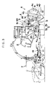
- FIG. 1 is a side elevational view of a conventional roll baler
- FIG. 2 is a plan view of the roll-baler, in which the roll-baler of the present invention has been incorporated;
- FIG. 3 is a side elevational view of the roll-baler as shown in FIG. 2 ;
- FIG. 4 is also a side elevational view of the power transmission mechanism for the roll-baler shown in FIG. 2 above;
- FIG. 5 is a plan view of the power transmission mechanism shown in FIG. 4 ;
- FIG. 6 is an explanatory diagram showing a state, when the net is delivered from the delivery mechanism.
- FIG. 7 is also an explanatory diagram showing a state, when the net as delivered from the delivery mechanism is wound on and around the roll bale.
- FIG. 2 is a plan view of the roll baler A, in which the device of the present invention is incorporated; and FIG. 3 is a side elevational view of the roll baler shown in FIG. 2 , with one part being cut away.
- a reference numeral I designates the machine body; a numeral 2 refers to the hopper; a reference numeral 3 indicates the transporting conveyor; a numeral 4 refers to the bale-shaping chamber; and a numeral 5 refers to the delivery mechanism.
- the machine body 1 is for supporting the hopper 2 and the bale-shaping chamber 4 , etc., and is in the form of a frame which may be constructed in any appropriate configuration and structure. In the illustrated embodiment, it is formed in a chassis frame which is self-navigable on the travelling wheels 10 , 10 , . . .
- the roll baler A is constructed in a traction type.
- a connecting rod 11 In the forward end side of this machine body 1 , there are provided a connecting rod 11 , and a joint section of an input shaft 12 in the form of a universal joint shaft 13 .
- the front end of the connecting rod 11 is joined to the connecting hitch a equipped on the rear face of the vehicle body of the tractor T, and the universal joint 13 is connected to the PTO shaft 12 of the tractor T, as shown in FIG. 3 , whereby the roll baler A is pulled to travel by the tractor T, as shown in FIGS. 2 and 3 , and each and every operating part of the roll baler, as mounted on the machine body 1 is made to work by a prime mover on the side of the tractor T.
- the machine body 1 may be constructed in a self-navigable type roll baler having its prime mover mounted thereon, to thereby drive the travelling wheels 10 , 10 , and each and every operating part thereof.
- the hopper 2 is to receive temporarily the shaping material such as harvested and shredded farm product for fodder, or the like by means of the harvester H which is connectively mounted on the lateral face of the tractor T for pulling the machine body 1 as shown in FIG. 2 above.
- This hopper 2 is of a conventional type, with its upper face side being open to serve as the material receiving port, and with its bottom face side being open in a funnel shape to define the discharge port 20 , and is mounted on the machine body 1 at an appropriate position.
- the hopper is mounted on the machine body 1 at its appropriate position to the side of the front part of the machine body 1 .
- the agitators 6 , 6 , . . . there are supported, in parallel, the agitators 6 , 6 , . . . , each having agitating blades 61 provided on its rotational shaft 60 which crosses through the hopper interior.
- the transporting conveyor 3 is to send the shaping material discharged from the discharge port 20 of the abovementioned hopper 2 toward the receiving port 40 of the shaping chamber 4 .
- This transporting conveyor 3 is mounted on the machine body 1 between the lower position of the discharge port 20 of the hopper 2 and the receiving port 40 of the shaping chamber 4 , the construction of which will be described later in more detail.
- the bale-shaping chamber 4 is of a conventional type, and is to shape the shaping material sent into the receiving port 40 thereof into the roll bale R by means of the bale-shaping apparatus 41 comprising a tightbar which rotates in circulation, and which is installed within the baleshaping chamber 4 .
- This shaping chamber is mounted on the machine body 1 at a position in the conveying direction of the transporting conveyor with a predetermined space interval S along the abovementioned transporting direction.
- the bale-shaping chamber 4 is disposed at a position where the abovementioned space interval S is defined along the above mentioned transporting direction at one lateral side of the hopper 2 mounted on the machine body 1 .
- the shaping chamber 4 is fixedly mounted on the machine body, with its one half side being designated as a fixed side 4 a , and with its one other half side being designated as a rotational side 4 b , the latter being assembled and supported onto the abovementioned fixed side 4 a fastened to the machine body 1 , in a freely rotational manner around a hinge P as the center.
- the shaping chamber 4 is mounted on the lateral end part of the machine body 1 in such a manner that the bale-shaping chamber 4 may become open outwardly of the machine body 1 by the rotation of its rotational side 4 b.
- the shaping chamber 4 is disposed at a position spaced apart from the hopper 2 at its rearward direction with the abovementioned space interval S, and mounted on the machine body 1 .
- the shaping chamber 4 is mounted on the rear end part of the machine body 1 so as to cause the shaping chamber 4 to be mounted on the rear end part of the machine body 1 , so that the shaping chamber 4 becomes open rearwardly of the machine body 1 due to rotation of the rotating side 4 b.
- the delivery mechanism 5 is of a conventional type, which comprises: a roll 50 of the twine (or net) for packaging the shaping material which has completed its shaping into the roll bale within the abovementioned shaping chamber 4 ; a delivery roll 51 ; and a guide 52 .
- This delivery mechanism is provided on the upper part of the space interval S defined between the abovementioned hopper 2 and the shaping chamber 4 .
- the twine (or net) n to be delivered from this delivery mechanism 5 droops into the abovementioned space interval S, as shown in, FIG. 6 with its bottom end coming into contact with, and being guided by the transporting conveyor 3 disposed on the bottom part of the space interval S, whereby the twine (or net) is delivered onto and around the peripheral surface of the roll bale R rotating within the shaping chamber 4 , through the receiving port 40 of the bale-shaping chamber 4 , being carried on the transporting conveyor 3 , and becoming wound therearound.
- the transporting conveyor 3 which carries the shaping material discharged from the discharge port 20 of the abovementioned hopper 2 , is placed in the space interval S extending from beneath the discharge port 20 of the hopper 2 to the receiving port 40 of the bale-shaping chamber 4 through the bottom part of the space interval S, above which is installed the abovementioned delivery mechanism 5 .
- This transporting conveyor 3 is split at an intermediate position in its transporting direction to be separated into the starting end side (front half side) and the terminal end side (rear half side), with its starting end side being made as the hopper-side transporting conveyor 3 a and mounted on the machine body 1 by disposing the same in the space from beneath the discharge port 20 of the hopper 2 toward the front end part of the abovementioned space interval S, while, with its terminal end side being made as the shaping-chamber-side transporting conveyor 3 b and disposed in the space extending from the bottom part of the abovementioned space interval S toward the receiving port 40 of the shaping chamber 4 , and with its starting end part of the shaping-chamber-side transporting conveyor 3 b , in its transporting direction, being positioned below the terminal end part of the hopper-side transporting conveyor 3 a so as to overlap with the terminal end part of the terminal end part of the hopper-side transporting conveyor 3 a , in the up-and-down relationship and be mounted on the machine body 1 .
- the hopper-side transporting conveyor 3 b receives this material. As soon as the material is discharged from the end part of the conveyor 3 a , the shaping-chamber-side transporting conveyor 3 a takes over the material so as to forward it to the receiving port 40 of the bale-shaping chamber 4 .
- these hopper-side transporting conveyor 3 a and shaping-chamber-side transporting conveyor 3 b are each linked to a drive mechanism so as to perform on-off control for their independent drive.
- the linkage of these transporting conveyors 3 a , 3 b to this drive mechanism will be explained in reference to the illustrated embodiment shown in FIGS. 4 and 5 .
- the rear end side of the input shaft 12 which is supported on the machine body 1 is connected to a transmission shaft 71 which is pivotally and laterally supported on a power transmission case 70 , through a power transmission mechanism (not shown in the drawing) which is accommodated in the interior of the power transmission case 70 supportively mounted on the machine body 1 in its middle part at a position before and after the machine body, and in the substantially center position at the left and right position of the machine body 1 .
- a power transmission mechanism (not shown in the drawing) which is accommodated in the interior of the power transmission case 70 supportively mounted on the machine body 1 in its middle part at a position before and after the machine body, and in the substantially center position at the left and right position of the machine body 1 .
- the shaft end part of this power transmission shaft 71 at both left and right sides thereof is connected to a power transmission wheel 72 fitted on the roll shaft 30 at the terminal end side of the abovementioned hopper-side transporting conveyor 3 a through a power transmission chain 73 .
- the power transmission wheel 72 is interlocked with a clutch 74 which performs on-off operations by the action of a clutch lever with respect to the roll shaft 30 .
- the power transmission wheel 72 is linked with the drive shaft 6 a of the abovementioned parallely arranged agitators 6 , 6 , . . . , so as to effect driving and stopping of the hopper-side transporting conveyor 3 a and the agitators 6 , 6 , . . . by the on-off operation of the clutch 74 .
- the other shaft end part (the left end side in FIG. 5 ) of the power transmission shaft 71 it is linked to the shaft end part of one of the roll-shaping drive shaft 76 (left side in FIG. 5 ), through the power transmission chain 75 , and the other shaft end part of the roll-shaping drive shaft 76 is linked to the roll shaft 31 of the terminal end side of the shaping-chamber-side transporting conveyor 3 b , through the power transmission chain 77 .
- this roll-shaping drive shaft 76 is linked the net-delivery roller shaft 53 of the delivery mechanism 5 , through the power transmission mechanism 78 , to thereby perform driving of the hopper-side transporting conveyor 3 a , the agitators 6 , the shaping-chamber-side transporting conveyor 3 b , the bale-shaping device 41 within the shaping chamber 4 , and the delivery mechanism 5 for twine (or net).
- the clutch 74 is brought to its “off’ state to thereby cause the hopper-side transporting conveyor 3 a and the agitators 6 to cease their driving.
- a clutch (not shown in the drawing) which actuates the delivery mechanism 5 by bringing the power transmission mechanism to its “on” state, when the roll bale R to be formed within the shaping chamber 4 is shaped to a predetermined roll-diameter or pressure, and when the sensor 8 which senses its shaping pressure performs the sensing action.
- the delivery mechanism 5 is actuated.
- the sensing device 8 performs its percepting action to sense the shaping pressure
- the delivery mechanism 5 is actuated to its “on” state.
- the sensing device 8 which senses that the shaping material to be formed into the roll bale within the shaping chamber 4 may be constructed in an electrical type.
- the sensing action which is achieved by catching the movement of the rotational side 4 b of the shaping chamber 4 , which rotates on the pivot of the hinge P, by means of a limit switch to emit an electrical signal.
- the clutch to control on-off operations of the delivery mechanism 5 which is controlled by its sensing action may also be an electrical type by use of an electromagnetic clutch.
- the clutch 74 to be provided between the hopper-side transporting conveyor 3 a and the power transmission shaft 71 may be constructed with the electromagnetic clutch.
- the clutch 74 is brought to its “on” state to stop the action of the hopper-side transporting conveyor 3 a and the agitators 6 , or the clutch to control the driving of the delivery mechanism 5 is brought to its “on” state to actuate the delivery mechanism 5 , thereby making it possible to deliver the twine (or net) to perform the packaging of the roll bale with no shaping material being discharged.
- a sensor s shown in FIG. 6 , is provided in the intermediate position between the delivery mechanism 5 and the shaping chamber 4 for sensing the twine (or net) n to be delivered from the delivery mechanism 5 and be guided into the receiving port 40 of the bale-shaping chamber 4 .
- the tractor operator can be alerted by a flashing patrol lamp L which is provided on the upper surface of the case 14 having therein the delivery mechanism 5 incorporated or a warning device such as buzzer, etc. to be placed on any appropriate location on the machine body 1 .
- the roll baler according to the present invention is so constructed that the transporting conveyor 3 for carrying the shaping material discharged from the discharge port 20 of the hopper 2 into the receiving port 40 of the bale-shaping chamber 4 is divided into two of.
- the hopper-side transporting conveyor 3 a which carries the shaping material discharged from the discharge port 20 of the hopper 2 up to a position Just in front of, and beneath, the delivery mechanism 5 for delivering the twine (or net); and the bale-shaping-chamber side transporting conveyor 3 b which takes over the bale-shaping material discharged from the terminal end of the hopper-side transporting conveyor 3 a to the receiving port 40 of the bale-shaping chamber 4 , and each of these transporting conveyors 3 a and 3 b is driven independently from the other, it becomes possible to replenish the shaping material into the roll bale, being shaped in the shaping chamber 4 , without seizing no excessive shaping material.
- the present invention solves the problem of bale-shaping material adhering onto the outer periphery of the twine (or net), when the roll bale as shaped and packaged is to be discharged from the shaping chamber. Accordingly, there is no shaping material dropping off from the material storage hopper during the bale-shaping operation.
- the hopper-side transporting conveyor is stopped to interrupt feeding of the bale-shaping material, during which the twine (or net) is fed and wound on and around the outer periphery of the completed roll bale and discharged from the shaping chamber after its packaging.
- bale-shaping operation can be done while the machine body is travelling, and bale-shaping material is fed into the hopper, whereby a high efficiency operation can be effectively attained.
Landscapes
- Life Sciences & Earth Sciences (AREA)
- Environmental Sciences (AREA)
- Storage Of Harvested Produce (AREA)
- Filling Or Emptying Of Bunkers, Hoppers, And Tanks (AREA)
Abstract
Description
Claims (3)
Applications Claiming Priority (2)
| Application Number | Priority Date | Filing Date | Title |
|---|---|---|---|
| JP2002-303967 | 2002-10-18 | ||
| JP2002303967A JP3843056B2 (en) | 2002-10-18 | 2002-10-18 | Roll baler |
Publications (2)
| Publication Number | Publication Date |
|---|---|
| US20040074209A1 US20040074209A1 (en) | 2004-04-22 |
| US7003933B2 true US7003933B2 (en) | 2006-02-28 |
Family
ID=32040851
Family Applications (1)
| Application Number | Title | Priority Date | Filing Date |
|---|---|---|---|
| US10/669,681 Expired - Lifetime US7003933B2 (en) | 2002-10-18 | 2003-09-25 | Roll-baler |
Country Status (6)
| Country | Link |
|---|---|
| US (1) | US7003933B2 (en) |
| EP (1) | EP1410709B1 (en) |
| JP (1) | JP3843056B2 (en) |
| KR (1) | KR100935557B1 (en) |
| DE (1) | DE60312097T2 (en) |
| ES (1) | ES2280696T3 (en) |
Cited By (18)
| Publication number | Priority date | Publication date | Assignee | Title |
|---|---|---|---|---|
| US20090007537A1 (en) * | 2007-07-06 | 2009-01-08 | Her Majesty The Queen In Right Of Canada As Represented By The | Device and method for harvesting woody crops |
| KR100935557B1 (en) | 2002-10-18 | 2010-01-07 | 가부시키가이샤 타카키타 | Roll baler |
| US20110023440A1 (en) * | 2009-07-31 | 2011-02-03 | Agco Corporation | Method For Projecting Biomass From A Combine Harvester |
| US20110023439A1 (en) * | 2009-07-31 | 2011-02-03 | Agco Corporation | Biomass Deflector |
| US20110023436A1 (en) * | 2009-07-31 | 2011-02-03 | Agco Corporation | Baler Tongue for Collecting Biomass |
| US20110023437A1 (en) * | 2009-07-31 | 2011-02-03 | Agco Corporation | Baler Collector For Collecting Biomass From A Combine Harvester |
| US20110023435A1 (en) * | 2009-07-31 | 2011-02-03 | Agco Corporation | Biomass Baler |
| US20110239607A1 (en) * | 2010-03-31 | 2011-10-06 | Weyerhaeuser Nr Company | Combination biomass harvester and baler |
| US20120124956A1 (en) * | 2010-11-18 | 2012-05-24 | Oakes Scott D | Method and Apparatus for Harvesting a Grain Crop |
| US20120297992A1 (en) * | 2011-05-24 | 2012-11-29 | Oakes Scott D | Continuous Baler with Surge Bin |
| US20130074465A1 (en) * | 2011-09-22 | 2013-03-28 | Pioneer Hi-Bred International, Inc. | System, apparatus, and method for cutting, windrowing, and bailing material in a single pass |
| US8443580B2 (en) | 2009-07-31 | 2013-05-21 | Agco Corporation | Baler pickup for collecting biomass from a combine harvester |
| US9345196B1 (en) * | 2014-11-05 | 2016-05-24 | Deere & Company | Cotton handling system with mechanical sequencing |
| US10257987B2 (en) | 2014-07-23 | 2019-04-16 | Cnh Industrial America Llc | Feeding system for an agricultural implement |
| WO2020223766A1 (en) * | 2019-05-07 | 2020-11-12 | Glenvar Pastoral Company Pty Ltd | Combine harvester power apparatus |
| US20220248609A1 (en) * | 2019-07-16 | 2022-08-11 | Cnh Industrial America Llc | Bale wrapping system |
| US11432465B2 (en) * | 2014-05-19 | 2022-09-06 | Gyro-Trac Corporation | Shredding and baling apparatus and method |
| US20240023485A1 (en) * | 2018-10-30 | 2024-01-25 | Cnh Industrial America Llc | Elevator Assembly for an Agricultural Harvester with a Storage Hopper having a Conveyor Therein |
Families Citing this family (10)
| Publication number | Priority date | Publication date | Assignee | Title |
|---|---|---|---|---|
| JP4761452B2 (en) * | 2006-02-07 | 2011-08-31 | 株式会社タカキタ | Remote control device for towed roll baler |
| JP4680137B2 (en) * | 2006-07-07 | 2011-05-11 | 株式会社タカキタ | Material supply control method for shredded roll baler |
| JP4933987B2 (en) * | 2007-08-31 | 2012-05-16 | 株式会社Ihiスター | Roll baler |
| JP5060380B2 (en) * | 2008-04-24 | 2012-10-31 | 株式会社Ihiスター | Roll baler |
| KR200465117Y1 (en) | 2010-10-22 | 2013-02-04 | 주식회사 명성 | Travelling crop supplying apparatus for bale silage |
| CA2949670C (en) * | 2014-05-19 | 2022-12-13 | Gyro-Trac Corporation | Baling apparatus and method |
| NO20150983A1 (en) * | 2015-07-31 | 2016-10-17 | Orkel Dev As | Compactor for bulk material |
| CN109292136B (en) * | 2018-09-14 | 2020-05-26 | 广州机施建设集团有限公司 | Assembly type partition plate packaging robot for building |
| US11547056B2 (en) * | 2020-03-11 | 2023-01-10 | Cnh Industrial America Llc | Frame assembly for an agricultural round baler |
| EP4458131A1 (en) * | 2023-04-26 | 2024-11-06 | Georg Rubenbauer | Agricultural press, in particular round baler |
Citations (9)
| Publication number | Priority date | Publication date | Assignee | Title |
|---|---|---|---|---|
| US2627223A (en) * | 1949-08-08 | 1953-02-03 | Howard J Berge | Baling machine for compacting straw and stalks from harvesting machines into cylindrical bales |
| US4602471A (en) * | 1985-05-28 | 1986-07-29 | Owens-Corning Fiberglas Corporation | Roll-up method and apparatus for mineral fiber pack |
| US5255501A (en) * | 1992-02-28 | 1993-10-26 | Mcwilliams Alexander | Baler for forming cylindrical bales |
| JPH0923739A (en) * | 1995-07-12 | 1997-01-28 | Atex Co Ltd | Bale-molding sensor of roll baler |
| US6032446A (en) * | 1998-04-06 | 2000-03-07 | Deere & Company | Densification method and apparatus for harvested cotton or other similar fibrous material |
| US6263650B1 (en) * | 1999-09-23 | 2001-07-24 | Deere & Company | Cotton harvester with accumulator |
| US6321507B1 (en) * | 1999-10-29 | 2001-11-27 | Owens Corning Fiberglas Technology, Inc. | Apparatus for packaging insulation material |
| US6591743B2 (en) * | 2001-02-01 | 2003-07-15 | Deere & Company | Cotton processing system and method of operation |
| US6729118B2 (en) * | 2001-06-06 | 2004-05-04 | Deere & Company | Non-stop large round baler |
Family Cites Families (6)
| Publication number | Priority date | Publication date | Assignee | Title |
|---|---|---|---|---|
| DE3039595A1 (en) * | 1980-10-21 | 1982-05-19 | Werner 5620 Velbert Doppstadt | Road verge mowing machine - has head discharging grass into baling mechanism |
| SE458250B (en) * | 1987-10-27 | 1989-03-13 | Joh Gjoennes Mek Verksted Jern | Machine for compressing grass |
| JP4001193B2 (en) * | 1999-06-28 | 2007-10-31 | 独立行政法人農業・食品産業技術総合研究機構 | Roll baler |
| DE19932336A1 (en) * | 1999-07-10 | 2001-01-11 | Lely Welger Maschinenfabrik Gm | Continuously operating agricultural baling press has two conveyors between crop storage chamber and press chamber |
| JP3976552B2 (en) * | 2001-11-19 | 2007-09-19 | 株式会社タカキタ | Roll baler |
| JP3843056B2 (en) | 2002-10-18 | 2006-11-08 | 株式会社タカキタ | Roll baler |
-
2002
- 2002-10-18 JP JP2002303967A patent/JP3843056B2/en not_active Expired - Lifetime
-
2003
- 2003-09-02 KR KR1020030061240A patent/KR100935557B1/en not_active Expired - Lifetime
- 2003-09-11 ES ES03255675T patent/ES2280696T3/en not_active Expired - Lifetime
- 2003-09-11 EP EP03255675A patent/EP1410709B1/en not_active Expired - Lifetime
- 2003-09-11 DE DE60312097T patent/DE60312097T2/en not_active Expired - Lifetime
- 2003-09-25 US US10/669,681 patent/US7003933B2/en not_active Expired - Lifetime
Patent Citations (9)
| Publication number | Priority date | Publication date | Assignee | Title |
|---|---|---|---|---|
| US2627223A (en) * | 1949-08-08 | 1953-02-03 | Howard J Berge | Baling machine for compacting straw and stalks from harvesting machines into cylindrical bales |
| US4602471A (en) * | 1985-05-28 | 1986-07-29 | Owens-Corning Fiberglas Corporation | Roll-up method and apparatus for mineral fiber pack |
| US5255501A (en) * | 1992-02-28 | 1993-10-26 | Mcwilliams Alexander | Baler for forming cylindrical bales |
| JPH0923739A (en) * | 1995-07-12 | 1997-01-28 | Atex Co Ltd | Bale-molding sensor of roll baler |
| US6032446A (en) * | 1998-04-06 | 2000-03-07 | Deere & Company | Densification method and apparatus for harvested cotton or other similar fibrous material |
| US6263650B1 (en) * | 1999-09-23 | 2001-07-24 | Deere & Company | Cotton harvester with accumulator |
| US6321507B1 (en) * | 1999-10-29 | 2001-11-27 | Owens Corning Fiberglas Technology, Inc. | Apparatus for packaging insulation material |
| US6591743B2 (en) * | 2001-02-01 | 2003-07-15 | Deere & Company | Cotton processing system and method of operation |
| US6729118B2 (en) * | 2001-06-06 | 2004-05-04 | Deere & Company | Non-stop large round baler |
Cited By (28)
| Publication number | Priority date | Publication date | Assignee | Title |
|---|---|---|---|---|
| KR100935557B1 (en) | 2002-10-18 | 2010-01-07 | 가부시키가이샤 타카키타 | Roll baler |
| US20090007537A1 (en) * | 2007-07-06 | 2009-01-08 | Her Majesty The Queen In Right Of Canada As Represented By The | Device and method for harvesting woody crops |
| US7743595B2 (en) * | 2007-07-06 | 2010-06-29 | Her Majesty The Queen In Right Of Canada As Represented By The Minister Of Agriculture And Agri-Food Canada | Device and method for harvesting woody crops |
| US8464508B2 (en) * | 2009-07-31 | 2013-06-18 | Agco Corporation | Biomass baler |
| US20110023440A1 (en) * | 2009-07-31 | 2011-02-03 | Agco Corporation | Method For Projecting Biomass From A Combine Harvester |
| US20110023436A1 (en) * | 2009-07-31 | 2011-02-03 | Agco Corporation | Baler Tongue for Collecting Biomass |
| US20110023437A1 (en) * | 2009-07-31 | 2011-02-03 | Agco Corporation | Baler Collector For Collecting Biomass From A Combine Harvester |
| US20110023435A1 (en) * | 2009-07-31 | 2011-02-03 | Agco Corporation | Biomass Baler |
| US20110023439A1 (en) * | 2009-07-31 | 2011-02-03 | Agco Corporation | Biomass Deflector |
| US8490375B2 (en) * | 2009-07-31 | 2013-07-23 | Agco Corporation | Baler collector for collecting biomass from a combine harvester |
| US8443580B2 (en) | 2009-07-31 | 2013-05-21 | Agco Corporation | Baler pickup for collecting biomass from a combine harvester |
| US20110239607A1 (en) * | 2010-03-31 | 2011-10-06 | Weyerhaeuser Nr Company | Combination biomass harvester and baler |
| US8250843B2 (en) * | 2010-03-31 | 2012-08-28 | Weyerhaeuser Nr Company | Combination biomass harvester and baler |
| US20120124956A1 (en) * | 2010-11-18 | 2012-05-24 | Oakes Scott D | Method and Apparatus for Harvesting a Grain Crop |
| US8707865B2 (en) * | 2011-05-24 | 2014-04-29 | Scott D. Oakes | Continuous baler with surge bin |
| US9462753B2 (en) * | 2011-05-24 | 2016-10-11 | Scott D. Oakes | Continuous baler with surge bin |
| US20120297992A1 (en) * | 2011-05-24 | 2012-11-29 | Oakes Scott D | Continuous Baler with Surge Bin |
| US20150201561A1 (en) * | 2011-05-24 | 2015-07-23 | Scott D Oakes | Continuous Baler with Surge Bin |
| US8733073B2 (en) * | 2011-09-22 | 2014-05-27 | E I Du Pont De Nemours And Company | System and apparatus for cutting, windrowing, and baling material in a single pass |
| US20130074465A1 (en) * | 2011-09-22 | 2013-03-28 | Pioneer Hi-Bred International, Inc. | System, apparatus, and method for cutting, windrowing, and bailing material in a single pass |
| US11432465B2 (en) * | 2014-05-19 | 2022-09-06 | Gyro-Trac Corporation | Shredding and baling apparatus and method |
| US10257987B2 (en) | 2014-07-23 | 2019-04-16 | Cnh Industrial America Llc | Feeding system for an agricultural implement |
| US9345196B1 (en) * | 2014-11-05 | 2016-05-24 | Deere & Company | Cotton handling system with mechanical sequencing |
| US20240023485A1 (en) * | 2018-10-30 | 2024-01-25 | Cnh Industrial America Llc | Elevator Assembly for an Agricultural Harvester with a Storage Hopper having a Conveyor Therein |
| US12150411B2 (en) * | 2018-10-30 | 2024-11-26 | Cnh Industrial America Llc | Elevator assembly for an agricultural harvester with a storage hopper having a conveyor therein |
| WO2020223766A1 (en) * | 2019-05-07 | 2020-11-12 | Glenvar Pastoral Company Pty Ltd | Combine harvester power apparatus |
| US20220248609A1 (en) * | 2019-07-16 | 2022-08-11 | Cnh Industrial America Llc | Bale wrapping system |
| US12364205B2 (en) * | 2019-07-16 | 2025-07-22 | Cnh Industrial America Llc | Bale wrapping system |
Also Published As
| Publication number | Publication date |
|---|---|
| KR20040034383A (en) | 2004-04-28 |
| EP1410709A1 (en) | 2004-04-21 |
| EP1410709B1 (en) | 2007-02-28 |
| JP2004135594A (en) | 2004-05-13 |
| ES2280696T3 (en) | 2007-09-16 |
| US20040074209A1 (en) | 2004-04-22 |
| KR100935557B1 (en) | 2010-01-07 |
| DE60312097D1 (en) | 2007-04-12 |
| JP3843056B2 (en) | 2006-11-08 |
| DE60312097T2 (en) | 2007-08-30 |
Similar Documents
| Publication | Publication Date | Title |
|---|---|---|
| US7003933B2 (en) | Roll-baler | |
| EP1312253B1 (en) | Roll-baler | |
| CN102781219B (en) | Continuous round baler with pick-up | |
| US6644006B1 (en) | Remote reverse control for pick-up rotor | |
| US6421992B1 (en) | Cotton harvester with two bale chambers | |
| EP0337006B1 (en) | Baling machine for forming cylindrical bales of crop | |
| US6651418B1 (en) | Modular pickup, stuffer, and rotor | |
| US5025992A (en) | Hay feeding apparatus | |
| US11904566B1 (en) | Pine straw baling apparatus and method | |
| WO2002076184A1 (en) | A baler | |
| CN110972729B (en) | Full-automatic round baler | |
| EP0087432B1 (en) | Baler | |
| CN209983124U (en) | Full-automatic round bundle bundling machine | |
| CN115009641B (en) | Traction type straw bale breaker and agricultural machinery | |
| CA1177366A (en) | Self-loading bale disintegrating machine | |
| US20210259155A1 (en) | Agricultural baler with rolls having overlapping extensions | |
| JP3886508B2 (en) | Roll baler | |
| JPH0356688B2 (en) | ||
| JP4107944B2 (en) | Blow guide device for molding material in hopper of roll baler | |
| WO2021224706A1 (en) | A baler | |
| CN115005466B (en) | Towed straw fodder production line and agricultural machine | |
| JPH08151U (en) | On-board shredder packing device | |
| JP4595049B2 (en) | Roll baler | |
| US5327711A (en) | Baler feeding apparatus | |
| KR20250136175A (en) | Silage forage feeder with conveyor |
Legal Events
| Date | Code | Title | Description |
|---|---|---|---|
| AS | Assignment |
Owner name: TAKAKITA CO., LTD., JAPAN Free format text: ASSIGNMENT OF ASSIGNORS INTEREST;ASSIGNORS:FUKUMORI, KOUICHI;MURAKI, AKIRA;UEMURA, YUJI;AND OTHERS;REEL/FRAME:014927/0981 Effective date: 20030701 Owner name: INSTITUTE OF AGRICULTURAL MACHINERY BIO-ORIENTED T Free format text: ASSIGNMENT OF ASSIGNORS INTEREST;ASSIGNORS:FUKUMORI, KOUICHI;MURAKI, AKIRA;UEMURA, YUJI;AND OTHERS;REEL/FRAME:014927/0981 Effective date: 20030701 |
|
| STCF | Information on status: patent grant |
Free format text: PATENTED CASE |
|
| FPAY | Fee payment |
Year of fee payment: 4 |
|
| FPAY | Fee payment |
Year of fee payment: 8 |
|
| AS | Assignment |
Owner name: INCORPORATED ADMINISTRATIVE AGENCY NATIONAL AGRICU Free format text: CHANGE OF NAME;ASSIGNOR:INSTITUTE OF AGRICULTURAL MACHINERY BIO-ORIENTED TECHNOLOGY RESEARCH ADVANCEMENT INSTITUTION;REEL/FRAME:043722/0707 Effective date: 20060401 |
|
| FEPP | Fee payment procedure |
Free format text: MAINTENANCE FEE REMINDER MAILED (ORIGINAL EVENT CODE: REM.) |
|
| AS | Assignment |
Owner name: NATIONAL AGRICULTURE AND FOOD RESEARCH ORGANIZATIO Free format text: CHANGE OF NAME;ASSIGNOR:INCORPORATED ADMINISTRATIVE AGENCY NATIONAL AGRICULTURE AND FOOD RESEARCH ORGANIZATION;REEL/FRAME:044965/0655 Effective date: 20150401 |
|
| AS | Assignment |
Owner name: TAKAKITA CO., LTD., JAPAN Free format text: ASSIGNMENT OF ASSIGNORS INTEREST;ASSIGNOR:NATIONAL AGRICULTURE AND FOOD RESEARCH ORGANIZATION;REEL/FRAME:044964/0796 Effective date: 20180201 |
|
| FEPP | Fee payment procedure |
Free format text: ENTITY STATUS SET TO SMALL (ORIGINAL EVENT CODE: SMAL) |
|
| FEPP | Fee payment procedure |
Free format text: 11.5 YR SURCHARGE- LATE PMT W/IN 6 MO, SMALL ENTITY (ORIGINAL EVENT CODE: M2556) |
|
| MAFP | Maintenance fee payment |
Free format text: PAYMENT OF MAINTENANCE FEE, 12TH YR, SMALL ENTITY (ORIGINAL EVENT CODE: M2553) Year of fee payment: 12 |