US698229A - Press for baling hay, cotton, &c. - Google Patents
Press for baling hay, cotton, &c. Download PDFInfo
- Publication number
- US698229A US698229A US8682701A US1901086827A US698229A US 698229 A US698229 A US 698229A US 8682701 A US8682701 A US 8682701A US 1901086827 A US1901086827 A US 1901086827A US 698229 A US698229 A US 698229A
- Authority
- US
- United States
- Prior art keywords
- follower
- baling
- press
- turn
- post
- Prior art date
- Legal status (The legal status is an assumption and is not a legal conclusion. Google has not performed a legal analysis and makes no representation as to the accuracy of the status listed.)
- Expired - Lifetime
Links
- 229920000742 Cotton Polymers 0.000 title description 4
- 230000007246 mechanism Effects 0.000 description 4
- 230000015572 biosynthetic process Effects 0.000 description 1
- 238000010276 construction Methods 0.000 description 1
- 235000015250 liver sausages Nutrition 0.000 description 1
- 230000004048 modification Effects 0.000 description 1
- 238000012986 modification Methods 0.000 description 1
- 229920000136 polysorbate Polymers 0.000 description 1
Images

Classifications
-
- B—PERFORMING OPERATIONS; TRANSPORTING
- B30—PRESSES
- B30B—PRESSES IN GENERAL
- B30B9/00—Presses specially adapted for particular purposes
- B30B9/30—Presses specially adapted for particular purposes for baling; Compression boxes therefor
- B30B9/305—Drive arrangements for the press ram
- B30B9/3053—Hand- or foot-operated presses
Definitions
- This invention relates to the type of presses provided with means for tamping eachcharge until the box or baling-chamber is filled and with independent mechanism for compressing the charges into a bale of the required size.
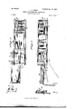
- Figure 1 is a side view of apress embodying the invention.
- Fig. 2 is a top View, the dotted lines showing the operation of the tamping mechanism.
- Fig. 3 is a vertical longitudinal section on the line X X of Fig. 2.
- Fig. 4 is a horizontal section on the line Y Y of Fig. 1.
- the press may occupy anyconvenient and desired position, although shown horizontally securing means common in this class of devices.
- the tamping and compressing mechanisms are located at the end of the press opposite to the baling-chainber and comprise a turn-post 7, sweep S, secured to one end of the turnpost, pitman 9 for connecting the stem of the follower with the sweep, and the cord or rope 10 for connecting the stem of the follower with the turn-post.
- the follower 11 mounted for reciprocating movement within the baling-chamber, is provided with a'stem composed of-spaced parallel bars 12, located one upon each side of the turn-post 7, so as to equalize the work and strain.
- the outer'endsof the spaced parallel bars 12 are connected bythe cross-piece 13, and a standard 14 is rigidly attached at its lower end to the outer end of thestem and has the pitman 9 pivotally connected thereto.
- a catch 15 is pivotally connected to the lower end of the standard 14 and is adapted to engage over a cross-bar 16 when the follower is forced home to the required extent, so as to prevent any rebound of the follower when released from the influence of the compressing mechanism.
- the cross-bar 16 prevents upward movement of the follower-stem, and downward movementthereof is prevented by means of the cross-bar 17 which is notched or cut away at its upper edge to receive the stem and prevent lateral movement thereof.
- pitman 9 has an opening 18 to receive a pin 19, applied to the sweep 8 a distance from the turn-post 7, and when the pin 19 is in engagement with the opening 18 the'follower is adapted to-be reciprocated by oscillating the sweep, as indicated by :the full and dotted lines in Fig. 2. a
- the cord or rope 10 is connected at one end to the turn-post 7, so as to wind thereon, and its outer end is connected with the crosspiece 13 at the outer end of the follower-stem. Hence upon rotation of the turn-post to wind the cord or rope 10 thereon the follower is advanced into the baling-chamber with great force and compresses the hay or other commodity contained therein.
- a second cord or rope 20 is connected at one end to the follower, and its opposite end is connected to the turnpost and is adapted to wind thereon in the reverse direction to the cord or rope 10, and by its means the follower is moved to the outer end of the baling-chamber after the formation of a bale.
- the doors 5 and 6 are secured and the door 4: opened to admit of a charge being supplied to the balingchamber, after which the door 4 is closed and the sweep 8 oscillated to move the follower within the baling-chamber and again return it to a normal position preliminary to placing a second charge within the baling-chamber.
- This operation is repeated until the balingchamber is filled, after which the pitman 9 is disconnected from the sweep 8 and the latter moved to turn the post 7, so as to wind the cord or rope 1 O thereon and force the follower within the baling-chamber, so as to compress the hay or other commodity to form a bale of predetermined size.
- the sweep is moved until the catch engages over the crossbar 16, when the bale is bound in any of the usual ways and is removed from the baling chamber by means of the doors 5 and (3.
- the follower is returned to a normal position by rotating the turn-post in the reverse direction, so as to wind the rope or cord thereon.
- a baling-chamber a follower adapted to move therein, a stem composed of spaced parallel bars attached to the follower, a turn-postpassed through the space formed between the said parallel bars, ropes or cords attached at one end to the turn-post and adapted to wind reversely thereon and having their opposite ends attached, respectively, to the follower and the outer end of the follower-stem, upper and lower cross-bars having the stem of the follower passed be tween them, a catch at the outer end of the stem to engage one of the said cross-bars, a sweep applied to the turn-post, and a pitman for connecting the stem with the sweep when tam ping the charges and disconnected from the sweep when pressing the bale, substantially as set forth.
Landscapes
- Engineering & Computer Science (AREA)
- Mechanical Engineering (AREA)
- Auxiliary Devices For And Details Of Packaging Control (AREA)
Description
"N0. 698,229. Patented Apr. 22, 1902..
J. soon; PRESS FOB BALING HAY, COTTON, 8w.
(Applicnt ion filed Dec. 21, 1901.: (N0 Model.)
2.Sheets-Sheet Lf J. T. soon. I
PBE SS FOB BALING HAY, COTTON, 6w.
- (Applicatibn filed Dec. 21, 1901.1 (No Model.)
mz' wnms PETERS co morauma. msumurou, a c.
Pate med Apr. 22, I902.
NITED STATES JAMES T. SCOTT, OF BUFFALO, ALABAMA.
.PRESS FORPBA'LING HAY, CO'TTON,"&.0.
SPECIFIGATION forming part Letters Patent N 0. 698,229, dated.Apri1 22, 1902. Application filed December 21, 1901. Serial No. 86,827. (No model.)
T0 aZZ whom itmay concern:
. Be it known that l, JAMES T. SCOTT, a citizen of the United States, residing at Buffalo, in the county of Chambers and State of Alabama, have invented certain new and useful Improvements in Presses for Baling Hay, Cotton, and the Like; and I do hereby declare the following to be a full, clear, and exact description of the invention, such as will enable others skilled in the art to which it appertains to make and use the same.
This invention relates to the type of presses provided with means for tamping eachcharge until the box or baling-chamber is filled and with independent mechanism for compressing the charges into a bale of the required size.
For a full description of the invention and the merits thereof and also to acquire a knowledge of the details of construction of the means for effecting the resultreference is to be had to the following description and drawings hereto attached.
While the essential and characteristic features of theinvention are susceptible of modification, still the preferred embodiment of the invention is illustrated in the accompanying drawings, in which Figure 1 is a side view of apress embodying the invention. Fig. 2 is a top View, the dotted lines showing the operation of the tamping mechanism. Fig. 3 is a vertical longitudinal section on the line X X of Fig. 2. Fig. 4 is a horizontal section on the line Y Y of Fig. 1.
Corresponding and like parts are referred to in the following description and indicated in all the views of the drawings by the same reference characters.
The press may occupy anyconvenient and desired position, although shown horizontally securing means common in this class of devices.
The tamping and compressing mechanisms are located at the end of the press opposite to the baling-chainber and comprise a turn-post 7, sweep S, secured to one end of the turnpost, pitman 9 for connecting the stem of the follower with the sweep, and the cord or rope 10 for connecting the stem of the follower with the turn-post.
The follower 11, mounted for reciprocating movement within the baling-chamber, is provided with a'stem composed of-spaced parallel bars 12, located one upon each side of the turn-post 7, so as to equalize the work and strain. The outer'endsof the spaced parallel bars 12 are connected bythe cross-piece 13, and a standard 14 is rigidly attached at its lower end to the outer end of thestem and has the pitman 9 pivotally connected thereto. A catch 15 is pivotally connected to the lower end of the standard 14 and is adapted to engage over a cross-bar 16 when the follower is forced home to the required extent, so as to prevent any rebound of the follower when released from the influence of the compressing mechanism. The cross-bar 16 prevents upward movement of the follower-stem, and downward movementthereof is prevented by means of the cross-bar 17 which is notched or cut away at its upper edge to receive the stem and prevent lateral movement thereof. The
pitman 9 has an opening 18 to receive a pin 19, applied to the sweep 8 a distance from the turn-post 7, and when the pin 19 is in engagement with the opening 18 the'follower is adapted to-be reciprocated by oscillating the sweep, as indicated by :the full and dotted lines in Fig. 2. a
The cord or rope 10is connected at one end to the turn-post 7, so as to wind thereon, and its outer end is connected with the crosspiece 13 at the outer end of the follower-stem. Hence upon rotation of the turn-post to wind the cord or rope 10 thereon the follower is advanced into the baling-chamber with great force and compresses the hay or other commodity contained therein. A second cord or rope 20 is connected at one end to the follower, and its opposite end is connected to the turnpost and is adapted to wind thereon in the reverse direction to the cord or rope 10, and by its means the follower is moved to the outer end of the baling-chamber after the formation of a bale. \Vhen the turn-post 7 is rotated to wind up the cord or rope 10, the cord or rope 20 is unwound, and upon rotating the turn-post in the reverse direction the cord or rope 20 is wound thereon and the cord or rope 1O unwound, as will be readily comprehended.
In the operation of the press the doors 5 and 6 are secured and the door 4: opened to admit of a charge being supplied to the balingchamber, after which the door 4 is closed and the sweep 8 oscillated to move the follower within the baling-chamber and again return it to a normal position preliminary to placing a second charge within the baling-chamber. This operation is repeated until the balingchamber is filled, after which the pitman 9 is disconnected from the sweep 8 and the latter moved to turn the post 7, so as to wind the cord or rope 1 O thereon and force the follower within the baling-chamber, so as to compress the hay or other commodity to form a bale of predetermined size. The sweep is moved until the catch engages over the crossbar 16, when the bale is bound in any of the usual ways and is removed from the baling chamber by means of the doors 5 and (3.
The follower is returned to a normal position by rotating the turn-post in the reverse direction, so as to wind the rope or cord thereon.
Having thus described the invention, what is claimed as new is- In combination, a baling-chamber, a follower adapted to move therein, a stem composed of spaced parallel bars attached to the follower, a turn-postpassed through the space formed between the said parallel bars, ropes or cords attached at one end to the turn-post and adapted to wind reversely thereon and having their opposite ends attached, respectively, to the follower and the outer end of the follower-stem, upper and lower cross-bars having the stem of the follower passed be tween them, a catch at the outer end of the stem to engage one of the said cross-bars, a sweep applied to the turn-post, and a pitman for connecting the stem with the sweep when tam ping the charges and disconnected from the sweep when pressing the bale, substantially as set forth.
In testimony whereof I afiix my signature in presence of two witnesses.
JAMES T. SCOTT.
XVitnesses:
E. M. BROOKS, J NO. IIOLLINGSWORTII.
Priority Applications (1)
| Application Number | Priority Date | Filing Date | Title |
|---|---|---|---|
| US8682701A US698229A (en) | 1901-12-21 | 1901-12-21 | Press for baling hay, cotton, &c. |
Applications Claiming Priority (1)
| Application Number | Priority Date | Filing Date | Title |
|---|---|---|---|
| US8682701A US698229A (en) | 1901-12-21 | 1901-12-21 | Press for baling hay, cotton, &c. |
Publications (1)
| Publication Number | Publication Date |
|---|---|
| US698229A true US698229A (en) | 1902-04-22 |
Family
ID=2766762
Family Applications (1)
| Application Number | Title | Priority Date | Filing Date |
|---|---|---|---|
| US8682701A Expired - Lifetime US698229A (en) | 1901-12-21 | 1901-12-21 | Press for baling hay, cotton, &c. |
Country Status (1)
| Country | Link |
|---|---|
| US (1) | US698229A (en) |
-
1901
- 1901-12-21 US US8682701A patent/US698229A/en not_active Expired - Lifetime
Similar Documents
| Publication | Publication Date | Title |
|---|---|---|
| US698229A (en) | Press for baling hay, cotton, &c. | |
| US680841A (en) | Baling-press. | |
| US315960A (en) | Upright-beater bal | |
| US132566A (en) | Improvement in presses for baling hay amd cotton | |
| US379414A (en) | Baling-press | |
| US265516A (en) | Baling-press | |
| US112224A (en) | Improvement in baling-presses | |
| US726284A (en) | Baling-press. | |
| US351610A (en) | Hay or cotton press | |
| US336293A (en) | Locking device for baling-press doors | |
| US729903A (en) | Baling-press. | |
| USRE7982E (en) | Improvement in hay and cotton presses | |
| US220019A (en) | Improvement in cotton and hay presses | |
| US395718A (en) | Baling-press | |
| US197207A (en) | Petefls | |
| US236827A (en) | Mckenzie | |
| US484757A (en) | Hay-press | |
| US594771A (en) | Baling-press | |
| US793639A (en) | Hay-press. | |
| US536093A (en) | Baling-press | |
| US420536A (en) | Baling-press | |
| US764925A (en) | Baling-press. | |
| US457632A (en) | Baling-press and method of baling | |
| US43132A (en) | Improvement in baling-presses | |
| US414036A (en) | Baling-press |