US6977586B2 - Associated articles identifying system - Google Patents
Associated articles identifying system Download PDFInfo
- Publication number
- US6977586B2 US6977586B2 US10/467,756 US46775603A US6977586B2 US 6977586 B2 US6977586 B2 US 6977586B2 US 46775603 A US46775603 A US 46775603A US 6977586 B2 US6977586 B2 US 6977586B2
- Authority
- US
- United States
- Prior art keywords
- radio
- tags
- tag
- radio tag
- article
- Prior art date
- Legal status (The legal status is an assumption and is not a legal conclusion. Google has not performed a legal analysis and makes no representation as to the accuracy of the status listed.)
- Expired - Lifetime, expires
Links
Images


Classifications
-
- G—PHYSICS
- G08—SIGNALLING
- G08B—SIGNALLING SYSTEMS, e.g. PERSONAL CALLING SYSTEMS; ORDER TELEGRAPHS; ALARM SYSTEMS
- G08B21/00—Alarms responsive to a single specified undesired or abnormal condition and not otherwise provided for
- G08B21/02—Alarms for ensuring the safety of persons
- G08B21/0202—Child monitoring systems using a transmitter-receiver system carried by the parent and the child
- G08B21/0227—System arrangements with a plurality of child units
-
- G—PHYSICS
- G08—SIGNALLING
- G08B—SIGNALLING SYSTEMS, e.g. PERSONAL CALLING SYSTEMS; ORDER TELEGRAPHS; ALARM SYSTEMS
- G08B21/00—Alarms responsive to a single specified undesired or abnormal condition and not otherwise provided for
- G08B21/02—Alarms for ensuring the safety of persons
- G08B21/0202—Child monitoring systems using a transmitter-receiver system carried by the parent and the child
- G08B21/0241—Data exchange details, e.g. data protocol
- G08B21/0247—System arrangements wherein the alarm criteria uses signal strength
-
- G—PHYSICS
- G08—SIGNALLING
- G08B—SIGNALLING SYSTEMS, e.g. PERSONAL CALLING SYSTEMS; ORDER TELEGRAPHS; ALARM SYSTEMS
- G08B21/00—Alarms responsive to a single specified undesired or abnormal condition and not otherwise provided for
- G08B21/02—Alarms for ensuring the safety of persons
- G08B21/0202—Child monitoring systems using a transmitter-receiver system carried by the parent and the child
- G08B21/0286—Tampering or removal detection of the child unit from child or article
-
- G—PHYSICS
- G08—SIGNALLING
- G08B—SIGNALLING SYSTEMS, e.g. PERSONAL CALLING SYSTEMS; ORDER TELEGRAPHS; ALARM SYSTEMS
- G08B21/00—Alarms responsive to a single specified undesired or abnormal condition and not otherwise provided for
- G08B21/02—Alarms for ensuring the safety of persons
- G08B21/0202—Child monitoring systems using a transmitter-receiver system carried by the parent and the child
- G08B21/0288—Attachment of child unit to child/article
-
- G—PHYSICS
- G08—SIGNALLING
- G08B—SIGNALLING SYSTEMS, e.g. PERSONAL CALLING SYSTEMS; ORDER TELEGRAPHS; ALARM SYSTEMS
- G08B25/00—Alarm systems in which the location of the alarm condition is signalled to a central station, e.g. fire or police telegraphic systems
- G08B25/01—Alarm systems in which the location of the alarm condition is signalled to a central station, e.g. fire or police telegraphic systems characterised by the transmission medium
- G08B25/10—Alarm systems in which the location of the alarm condition is signalled to a central station, e.g. fire or police telegraphic systems characterised by the transmission medium using wireless transmission systems
Definitions
- This invention relates to mechanisms for associating related objects. More particularly, it applies to a system for associating a mother with her own baby in a maternity ward. It also applies to the location of luggage and the like from amongst a collection of similar articles.
- Such bracelets have been built that include electronic transmission elements that provide a specific identification that is associated with the bracelet.
- Such electronic bracelets based on centralized signal reception and processing, have been used to monitor the presence of an infant or mother in a nursery or other room, the removal of an infant wearing such a bracelet from a nursery, and the presentation of an infant to its proper mother.
- Such existing systems rely on room-mounted and doorway-mounted sensors that receive signals emitted by the bracelets and process data received from the bracelets in a central processor. By assigning differing, distinct signals to each bracelet, the presence of each bracelet, and each corresponding infant and mother, in a given area can be monitored by a central electronic control system.
- the present invention is directed to addressing the above objectives.
- member objects from two sets of objects have the capacity to become “bonded” to each other by means of acquisition of information data by at least one object from one set, the detecting object, as to the identity of one or more members of the opposite set, the identifying objects.
- the detecting object is able to sense through wireless means, and assess through identification means associated with, and preferably carried by, the detecting object, the presence of either a bonded, identifying object from the opposite set, or a non-bonded identifying object from such set, that is present within a predetermined range.
- the detecting object may then provide an indication as to whether the sensed object is a bonded or non-bonded object.
- the indication may be in the form of an audio or visual signal, or an electronic signal that is emitted for immediate display or long term storage elsewhere, or is sent for storage in a memory location. It may be either affirmative or negative, signifying whether the sensed, identifying object is one to which the detecting object has been previously bonded—a “match”—; or is an identifying object from the opposite set to which the detecting object has not been bonded—a “mismatch”.
- the detecting object can optionally ignore the presence of a non-bonded object, emitting only affirmative signals when a bonded object is present. Or it may emit a signal in the presence of any candidate, preferably on an automatic basis, identifying object from the opposite set, providing an indication that the detected, identifying object is not a bonded object.
- the system can carry-out both functions. And as a still further alternative, the system can provide an indication when a bonded identifying object that has previously been present with a predetermined range of the detecting object, the detecting range, has moved beyond such range. This feature may be combined with the other features to provide multiple classes of output for an encounter between a detecting object and an identifying object.
- the detecting object is selected from a set of radio, infra-red or ultra-sonic equipped detecting bracelets to be worn by infants in a hospital nursery.
- the objects from the opposite set are radio, infra-red or ultra-sonic transmitting tags, e.g. bracelets, to be worn by a mother, or optionally, tags to identify parents, grandparents, the medication apparatus or the like associated with the infant in the hospital, or the doorway to a room or the like on a premises.
- objects to be bonded are brought into communication with each other, preferably in each other's presence, to permit the acquisition of identification data by an identification means carried by, or linked to the detecting object.
- Data is so provided to enable the detecting object to identify object(s) from the opposite set to which it is to be bonded.
- This data may be provided to the identification means by a variety of systems including radio or other wireless signals based on infra-red or ultra-sonic communication or the equivalent.
- Such means may also include a connection through wired circuit connection means.
- the communication channel may be direct or may include intermediate communication elements, provided, however, that the identification means linked to the detecting object acquires the data by which a matching or mis-matching identification can be established.
- Signals may be coded by their frequency, by frequency or amplitude modulations, by pulse modulation or by other known means.
- a signal receiving means is correspondingly associated with the identification means and detecting object.
- the identification means comprises a signal discrimination circuit that will decode the signal that carries the identification data.
- Identification data employed in the bonding process may be based on providing the objects from the opposite set with individual, unique identification codes. Such codes, equivalent to serial numbers, may be provided to the identifying objects at the time of their manufacture.
- the identification data may also be the equivalent of a password provided by the detecting object, or by an intermediate bonding means that communicates with both the detecting object and opposite, identifying object(s) to be bonded. Once the password has been acquired, the bonded identifying object(s) use this password in transmitting their identification data.
- This password may be drawn from a register of possible passwords so that the transmitted password is unique to the bonded objects. Or the password may be generated randomly in a manner that ensures that the transmitted password is functionally unique. This transfer of identification data need not be a mutual exchange.
- the opposite identifying object need not receive data on the identity of the detecting object.
- While a preferred application of the invention is the verification of relationships between proximate objects such as infants and parents in hospital maternity wards, the invention also has applications where it is desired to provide an out-of-range signal between associated objects. This may occur in cases where a traveller wishes to ensure that his/her laptop computer is not left behind, or as in mines where miners are expected to work as “buddies” who must always remain within a predetermined range of each other.
- a further application is to prevent children, pets or the elderly from wandering-off.
- an indicating signal is provided when the bonded objects move beyond a predetermined, detecting range of each other. This signal may emitted automatically when the not-detected signal condition occurs.
- the objects to be bonded are initially “versatile”.
- versatile is meant that any object from one set, the detecting object's set, may become bonded with an object from the opposite set, the identifying object's set.
- the acquisition of identification data in the bonding procedure operates without human selection of the identification data that is to be acquired in respect of the bonded objects. In this manner, the risk of human error arising in the bonding process is minimized.
- objects may be members of more than one paired set at the same time. For example, an object could serve as an identifying object, a parent tag, in one pair of sets with a baby's bracelet as the detecting object.
- the parent's tag may be equipped to serve as a detecting object with respect to a tag on a dedicated medical apparatus or special feeding bottles as the identifying object.
- the parents can both be identified, and can in turn, identify dedicated objects with the certainty that no error is occurring.
- the invention differs from prior art object locator systems by the capacity of initially versatile objects to become bonded to each other on the basis of identification data that is acquired in the identification process without human selection of the precise data being acquired. Bonding preferably occurs with the objects in each other's presence,—in situ—, at a location whereat the bonded objects will thereafter be associated with, e.g. connected or bonded to, articles or persons which are intended to be correlated.
- the invention in a preferred aspect, also allows the bonding process to be re-established afresh, with full bonding versatility, upon effecting a reset to clear the prior bonded states of the respective, bonded, detecting and identifying objects.
- a transfer of identification data necessarily occurs during a bonding period, established by activation of the bonding process.
- all identifying objects within a bonding range during a preset, bonding period provide identification data to the detecting object, thus creating a multiple group of bonded objects. If only one identifying object is present, reception of its identification data can be used to close the bonding period.
- the termination of the bonding period may be manually established by a user input or automatically established by the identifying object after, reception of identification signals from a pre-selected number of identifying objects.
- the detecting object and identifying object(s) from the opposite set may be, in one variant, exclusively bonded to each other.
- the bonding period may be re-opened to effect further bonding and expand the class of bonded identifying objects.
- the invention applies to selected members from two distinct sets. These sets contain members that are versatile in their capacity to be correlated with any object from the other set, i.e. to become “bonded” to one or more of such objects. Bonding occurs in conjunction with the transmission of automatically generated identification data. Bonded objects then have the capability to provide an indication preferably on an automatic basis, that distinguishes whether members from opposite sets, which are present within have moved within, or optionally have moved beyond, a predetermined, detecting range of each other are, or are not, members that have been previously bonded to each other.
- FIG. 1 depicts pictorially respective sets of baby bracelets and parent tags that are initially versatile in the sense that any member of one set can become bonded to a member of the other set.
- FIG. 2 depicts pictorially the selection of a single baby bracelet for bonding with a parent's tag through intermediate circuitry that permits the bracelet to store identification data unique to the bonded parent's tag.
- FIG. 3 is a pictorial overhead view of a hospital nursery with multiple infants carrying bonded bracelets, and mothers carrying bonded parent's tags located in hospital rooms beyond the range of detection and communication between bracelets and tags.
- FIG. 4 depicts a single bonded bracelet on an infant as it enters the predetermined detection range of a correlated, bonded parent's tag in the form of a bracelet, worn by a mother, the baby's bracelet emitting an affirmative, matching signal.
- FIG. 5 corresponds to FIG. 4 wherein the bracelet, upon approaching within the detecting range of a mother's tag to which it has not been bonded emits a non-matching warning signal.
- FIG. 6 is a block diagram depiction of the functional elements of a baby's bracelet and parent tag as they are interconnected during the bonding procedure depicted in FIG. 2 whereby the parent tag originates the identification data.
- FIG. 7 corresponds to FIG. 6 , modified to the case where the baby's bracelet originates the identification data and the parent tag stores and adopts such data.
- FIG. 8 is a block diagram depiction of the functional elements of a bonded pair of baby's bracelet and parent tag as they come within range of each other as depicted in FIG. 4 with provision for the baby's bracelet to send signals to a central processor and monitoring station.
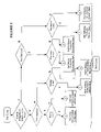
- FIG. 9 is a logic flow chart showing signal condition analysis for the multiple cases of detection of objects, bonded and not bonded, coming within the detecting range and an object moving beyond the detecting range.
- FIG. 10 depicts the deactivation of a bonded baby's bracelet by the severing of the attachment strap of the bracelet.
- FIG. 11 depicts two mine workers active within range of each other.
- FIG. 12 depicts the departure of one mine worker beyond range leading to emission of an out-of-range alarm signal.
- a first set of objects 1 consists of individual baby ankle bracelets 3 having receiving 4 and optionally transmission 5 , elements.
- a second set of objects 2 consisting of parent tags 6 , optionally in the form of bracelets, provided with transmission 7 and, optionally reception 8 , elements. Initially, any bracelet 3 of the first set may be correlated or “bonded” with any tag 6 of the second set 2 .
- FIG. 2 the bonding process is depicted by which, in the case depicted, a specific tag 6 A sends identification data 9 over wires 10 through linking circuitry 11 to a specific bracelet 3 A.
- This “bonding” procedure may be initiated by closing the loop of a conductive strap 33 when a bracelet 3 A is attached to a baby's limb.
- the bonding period following thereafter during which bonding may occur may be of a predetermined fixed length of time, may be manually terminated, or may conclude with the reception of one or more units of identification data 9 .
- the baby's bracelet 3 A may become bonded to such multiple parent tags 6 through serial or parallel access to the linking circuitry 11 .
- all parent tags would provide unique identification data and the bracelet 3 A would have the capacity to store multiple identities.
- multiple matched parent tags 6 could provide the same identification data 9 . After communication of this data 9 , the bracelet 3 A will be able to distinguish the specific tag 6 A, or tags, from the set 2 of tags 6 . This constitutes the bonding process.
- cribs 12 in a hospital nursery 23 contain infants 13 each wearing bracelets 3 .
- Mothers 14 in bedrooms 15 wear individual parent's bracelets or tags 16 .
- These parents tags 16 are equivalent to the tags 6 of FIG. 1 .
- the bracelets 3 in the nursery 23 are not able to detect the presence of the parent tags 16 in the hospital bedrooms 15 .
- FIG. 4 a baby 13 wearing a previously bonded bracelet 3 A is brought into the presence of a mother 14 wearing a similarly bonded parent's tag 16 A.
- the parent's tag 16 A emits repeated Very Low-Frequency—VLF radio signals 17 from its transmitter 24 , which signals 17 are sensed by the bracelet 3 A on entry into the detection range for the signals 17 present in the bedroom 15 .
- VLF radio signals have a near field component that falls-off with distance as a cubic power of the distance, defining an effective limit to transmission range.
- adjustment of the transmission power of the transmitters 24 in the parents tag 16 A will establish a predetermined detection range based upon the threshold signal strength that a baby's bracelet 3 A is able to detect.
- range detection means such as acoustic echo-location or electronic reflected wave, i.e. radar, or the equivalent may also be employed. In such cases, range evaluation circuitry would be included in the system.
- VLF radio signals of appropriately limited power the signal 17 is not detectable by the bracelet 3 A significantly beyond the entrance to the mother's room 15 .
- the bracelet 3 A detects the signal and the identification data 9 of the parent's tag 16 A—previously exchanged in the bonding procedure.
- the bracelet 3 A may then emit, at least for a period of time, an audible signal 18 indicating that a match exists between the bracelet 3 A and tag 16 A. Preferably, this signal occurs automatically without human intervention. Similarly a match indicating light (not shown in FIG. 4 , see FIG. 8 ) may be illuminated.
- an event report may be emitted by radio or infra-red transmission for reception by a building-mounted receiver 51 for transfer to a remotely located central control processor 52 .
- the event may be presented, e.g. displayed on a video monitor 58 or recorded for later reference. If the mother's tag 16 A contains a receiver it may provide the matching/non-matching indication. All of these outputs constitute output indications of the events that have occurred.
- the indication signal may be suspended, as by a time-out shut-off circuit within signal indication means 32 .
- This signal may be reactivated if the baby bracelet 3 A is moved beyond the detection range e.g. out of the room 15 .
- Short interruptions in the ongoing reception of identification data 9 may be accepted without re-emitting a match-signal in order to accommodate temporary disruptions in inter-bracelet communications. Such interruptions could arise from antennae misalignment, or from the presence of an intervening, blocking object between the bracelets 3 A, 16 A.
- FIG. 5 the same scene is depicted wherein the bracelet 3 A and parent's tag 16 B are not a match, and the VLF signal 17 A contains a non-matching identification code.
- a corresponding non-matching alert indication 19 is emitted by the bracelet 3 A. This may be an alternate or cumulative feature to those depicted in respect of FIG. 4 . Again, other output indications may also arise from such an event.
- the detecting object 3 A may not only have a time-out limit to signal emission but may contain circuitry to suppress emission of a mismatch signal 17 A so long as a matching signal 17 is being received.
- a momentary mismatch signal 17 A may be produced by such circuitry, followed by suppression of further signals.
- the tag 16 A has a stored identification code 21 , akin to a serial number, available in a parent tag memory 25 to transmit during bonding.
- the bracelet 3 A receives the identification signal 9 through the linking circuitry 11 from the tag 16 A.
- the identification code 21 in this case originates from the parent tag 16 A.
- the code 21 is stored in a bracelet memory 26 accessible by comparison circuitry 22 , both of which are located within the bracelet 3 A.
- the comparison circuitry 22 is subsequently employed to assess signals received from further identifying tags 16 . This completes the bonding process.
- FIG. 7 an alternate bonding process is shown.
- the bracelet 3 A receives one of the regular VLF signals 17 issuing from the parent tag 16 A by emission from the parent tag transmitter 24 through an antenna 36 .
- this initial signal does not include an identification code which is specific to the parent tag 16 A.
- the bracelet 3 A provides such specific identification code 21 by a return radio frequency signal 17 A emitted by a transmitter 31 through antenna 56 .
- the parent tag 16 A which includes a receiver 39 , decoder 40 and parent tag memory 25 A, receives and stores this code 21 for subsequent re-transmission.
- the link for this alternate process need not, however, be wireless. Instead it could rely on directly wired, intermediate linking circuitry 11 . Equally, the procedures of FIG. 6 could be carried-out by wireless means.
- the bonding process may be initiated by electrically activating the baby's bracelet 3 to await the reception of identification data 9 .
- This may be conveniently effected by providing the bracelet 3 with a conducting strap 33 that closes an electrical circuit when the strap 33 forms a loop around a baby's limb.
- the bracelet memory 26 may be made accessible for only a limited period of time. This establishes a bonding period during which, and only during which, the initial bonding communication may be perfected until a reset occurs.
- the bracelet 3 A may contain circuitry akin to circuitry 50 allowing the bonding period to be re-opened and allow further bonding to be extended to additional parent tags 16 .
- the bonding period may be kept open until identification data 9 has been received from one, or a predetermined multiple number of identifying sources.
- the bonding window could close afer a predetermined interval. Thereafter, a fresh activation procedure would be required to reopen the bonding window.
- FIG. 8 the functional elements within a bonded pair of baby's bracelet 3 A and parent tag 16 A are shown, operating as they would when the bracelet 3 A comes within range of the coded VLF radio signal 17 that is being emitted by the parent tag 16 A.
- the bracelet 3 A contains the following components: a VLF receiver 27 ; an antenna 56 ; a microprocessor 28 connected to the baby bracelet memories 26 and computer identification comparison circuitry 22 ; actuating input means e.g.
- the bracelet 3 A may include a radio transmitter 57 and antenna 34 to provide a radio output indication 35 to a remote, centralized processor 52 and otherwise communicate with such processor 52 .
- the parent tag contains the following components: a VLF transmitter 24 ; VLF antennae 36 ; a microprocessor 37 with access to the parent tag memories 25 ; an optional receiver 39 , and decoder means 40 accessible by the microprocessor 37 .
- FIG. 9 depicts the logic flow analysis that may be executed by the computer circuitry 22 contained within the bracelet 3 A. Both bonded and non-bonded objects from the opposite set may come within range.
- the logic flow analysis of FIG. 9 establishes the type of output, signal that the indication means 32 provides.
- the system preferably incorporates a means akin to and/or incorporated into activation means 50 by which the bonded state may be deactivated or purged, allowing a reset following which a bracelet 3 A may be freshly bonded to a new parent tag 16 by a reinitiation of the bonding procedure.
- Deactivation may conveniently be precipitated by a button 53 , or by severing, as in FIG. 10 , a bracelet strap 33 which carries an electrical link to circuitry within the bracelet 3 A. This is depicted in FIG. 10 . Installation of a fresh strap 33 may then act equivalently to button 59 to reinitiate the bracelet's 3 computer circuitry and permit a fresh bonding operation to occur.
- This deactivation process may be subject to a delay or “time-out” period during which a loosened or momentarily disconnected strap may be reattached. Such an event would normally be monitored by a central processor as discussed below.
- an external signal monitoring system may also be employed.
- the bracelets of the invention may be employed in conjunction with a series of fixed local area receivers 51 that connect to a central processor 52 and display facility 58 .
- Existing systems monitoring infant location which rely on radio and infra-red signal detectors 51 receive and process identification signals emitted from bracelets 3 and tags 16 present within the range of such detectors 51 .
- the centralized processor 52 operating in parallel with the direct tag-to-tag wireless communication between parent tags 16 and infant bracelets 3 that are within inter-tag detection range of each other, may be sent, as shown in FIG. 8 , a signal 35 that corresponds to, with or without additional data, the signal 17 received by the bracelet 3 A.
- the centralized processor 52 can then log the event that has occurred, and display, through the display facility 58 , what type of encounter is occurring. When a mis-match is registered corrective action may be taken by hospital staff.
- the central processor 52 may also store in a memory 54 a record of such encounters for archival purposes.
- the period or duration of the encounter, or the absence of an encounter, can be monitored and an alert signal may be provided by the processor 52 when a predetermined period of permissible delay has been exceeded.
- the central processor 52 could provide a warning that such breastfeeding is overdue based on the absence of an expected encounter between a baby 13 and its mother 14 .
- the central processor 52 may also store in a memory 54 a record of such encounters for archival purposes.
- the location of matching tags may be monitored through portal-mounted devices 51 , which initiate signals when a match set of tags 3 A, 16 A are entering a restricted area such as a smoking room. Appropriate action may then be taken.
- a centralized processor 52 can also participate in the initiation of a bonding event. For example, when intermediate bond circuitry 11 is employed, such circuitry 11 may require a password authorization to be keyed-in, and the centralized processor 52 can assess the keyed-in data and send a signal through activation antenna 52 to enable the bonding process to proceed.
- bonding may only be enabled when the objects to be bonded are present at a specific locale, e.g. a birthing room.
- the portal-mounted devices 51 may be used to sense the entry of the objects to be bonded into the specific locale.
- the central processor 52 may then send a signal to such specific devices (or one of them) permitting bonding to proceed.
- FIGS. 11 and 12 depict the moving-out-of-range scenario, using mine buddies as the example.
- Miners 60 carry respectively an identifier tag 61 A and detecting tag 62 A, corresponding to a parent tag 16 and baby's bracelet 3 .
- These tags 61 A, 62 A have been bonded to each other, as indicated by the letter “A” as by any of the manners described above.
- miner's tags 61 A, 62 A are versatile in the sense that before becoming bonded, they are drawn from respective sets wherein any member of one set can be bonded to any member of the other set. This greatly facilitates the inventorying of these locator tags.
Landscapes
- Health & Medical Sciences (AREA)
- Child & Adolescent Psychology (AREA)
- General Health & Medical Sciences (AREA)
- Business, Economics & Management (AREA)
- Emergency Management (AREA)
- Physics & Mathematics (AREA)
- General Physics & Mathematics (AREA)
- Engineering & Computer Science (AREA)
- Computer Networks & Wireless Communication (AREA)
- Emergency Alarm Devices (AREA)
- Radar Systems Or Details Thereof (AREA)
- Transition And Organic Metals Composition Catalysts For Addition Polymerization (AREA)
Applications Claiming Priority (1)
| Application Number | Priority Date | Filing Date | Title |
|---|---|---|---|
| PCT/CA2001/000155 WO2002065421A1 (en) | 2001-02-13 | 2001-02-13 | Associated articles identifying system |
Publications (2)
| Publication Number | Publication Date |
|---|---|
| US20040080419A1 US20040080419A1 (en) | 2004-04-29 |
| US6977586B2 true US6977586B2 (en) | 2005-12-20 |
Family
ID=4143125
Family Applications (1)
| Application Number | Title | Priority Date | Filing Date |
|---|---|---|---|
| US10/467,756 Expired - Lifetime US6977586B2 (en) | 2001-02-13 | 2001-02-13 | Associated articles identifying system |
Country Status (7)
| Country | Link |
|---|---|
| US (1) | US6977586B2 (de) |
| EP (1) | EP1362335B1 (de) |
| AT (1) | ATE310296T1 (de) |
| CA (1) | CA2436798C (de) |
| DE (1) | DE60115096T2 (de) |
| ES (1) | ES2253349T3 (de) |
| WO (1) | WO2002065421A1 (de) |
Cited By (9)
| Publication number | Priority date | Publication date | Assignee | Title |
|---|---|---|---|---|
| US20050147141A1 (en) * | 2003-12-29 | 2005-07-07 | Sox Daniel J. | Methods and devices for forming a high-power coherent light beam |
| US20050148828A1 (en) * | 2003-12-30 | 2005-07-07 | Kimberly-Clark Worldwide, Inc. | RFID system and method for tracking environmental data |
| US20050280535A1 (en) * | 2004-06-18 | 2005-12-22 | Rf Technologies | Systems and methods for tagging and identification |
| US20060244601A1 (en) * | 2005-04-15 | 2006-11-02 | Takashi Nishimura | Information processing apparatus, control method of information processing apparatus, control program of information processing apparatus, and recording medium on which control program of information processing apparatus is recorded |
| US20060290519A1 (en) * | 2005-06-22 | 2006-12-28 | Boate Alan R | Two-way wireless monitoring system and method |
| US20080258516A1 (en) * | 2007-04-20 | 2008-10-23 | Meeker R&D, Inc. | Infant carrier handle |
| US20090219169A1 (en) * | 2006-02-20 | 2009-09-03 | Beatrice Marie Jacqueline Herwats | Method and System for Identifying and Handling (Tracing/Locating/Identifying to Receive Services) An Owner And Items In A Secure/Private Area |
| US20100217618A1 (en) * | 2009-02-25 | 2010-08-26 | Piccirillo Charles J | Event Detection Based on Location Observations and Status Conditions of Healthcare Resources |
| US8410926B1 (en) | 2010-05-07 | 2013-04-02 | Rf Technologies, Inc. | Alarm for security tag |
Families Citing this family (18)
| Publication number | Priority date | Publication date | Assignee | Title |
|---|---|---|---|---|
| US7204425B2 (en) * | 2002-03-18 | 2007-04-17 | Precision Dynamics Corporation | Enhanced identification appliance |
| US7388488B2 (en) * | 2003-10-30 | 2008-06-17 | Peter Lupoli | Method and system for storing, retrieving, and managing data for tags |
| AU2005216566A1 (en) * | 2004-02-27 | 2005-09-09 | John Griffits | Electronic sock sorting and mating system |
| US20070008169A1 (en) * | 2005-07-11 | 2007-01-11 | Conero Ronald S | A Radio Frequency Activated Integrated Circuit and Method of Disabling the Same |
| US20080007407A1 (en) * | 2006-07-05 | 2008-01-10 | De Elia Maximo M | Zone supervision system |
| WO2008033970A2 (en) * | 2006-09-14 | 2008-03-20 | Sloan Kettering Institute For Cancer Research | Automated association of patient care devices |
| US20080180213A1 (en) * | 2006-11-07 | 2008-07-31 | Flax Stephen W | Digital Intercom Based Data Management System |
| US8427319B2 (en) * | 2008-12-12 | 2013-04-23 | Infosys Technologies Limited | System and method for real time theft detection |
| US9729944B2 (en) * | 2013-12-27 | 2017-08-08 | Intel Corporation | Interchangable charm messaging wearable electronic device for wireless communication |
| CN103948378B (zh) * | 2014-04-14 | 2015-04-08 | 京东方科技集团股份有限公司 | 一种预警装置和预警方法 |
| FR3036213B1 (fr) * | 2015-05-13 | 2019-11-08 | Icare Technologies | Dispositif d'identification sous forme d'anneau muni d'un transpondeur radiofrequetiel |
| US9968142B2 (en) * | 2015-07-27 | 2018-05-15 | Rupal Asodaria | Nursing bracelet |
| JP7340771B2 (ja) * | 2018-05-28 | 2023-09-08 | パナソニックIpマネジメント株式会社 | 生体検知装置、生体検知方法、記録媒体、およびプログラム |
| US11315404B1 (en) * | 2018-12-27 | 2022-04-26 | Brian A. Greer | Wearable proximity alert system |
| CN111728804B (zh) * | 2020-07-24 | 2021-06-25 | 温州市人民医院 | 一种妇产科婴儿看护系统 |
| CN112150761A (zh) * | 2020-09-22 | 2020-12-29 | 复旦大学附属妇产科医院 | 一种院内患者防走失手环、系统及其使用方法 |
| DE102021100063A1 (de) * | 2021-01-05 | 2022-07-07 | Drägerwerk AG & Co. KGaA | Patientenverwaltungssystem |
| CN113034844B (zh) * | 2021-02-26 | 2023-06-27 | 广元市中心医院 | 一种新生儿安防报警系统 |
Citations (2)
| Publication number | Priority date | Publication date | Assignee | Title |
|---|---|---|---|---|
| US6144304A (en) * | 1995-08-16 | 2000-11-07 | Webb; Nicholas J. | Methods and apparatus for the secure identification of infants and parents in health care institutions |
| US6211790B1 (en) * | 1999-05-19 | 2001-04-03 | Elpas North America, Inc. | Infant and parent matching and security system and method of matching infant and parent |
Family Cites Families (8)
| Publication number | Priority date | Publication date | Assignee | Title |
|---|---|---|---|---|
| US4173016A (en) * | 1978-01-04 | 1979-10-30 | Dickson Carlisle H | Interpersonal-introduction signalling system |
| FR2615957A1 (fr) * | 1987-03-05 | 1988-12-02 | Dupuch Charles | Appareil portatif permettant a des personnes ayant ensemble des points communs, de s'identifier a distance, de se localiser et de se rencontrer |
| GB2275804A (en) * | 1993-03-06 | 1994-09-07 | Manjit Singh Bains | Child alarm/monitor |
| FI960002A0 (fi) * | 1996-01-02 | 1996-01-02 | Creativesco Oy | Personidentifierare |
| DE19801666A1 (de) * | 1998-01-17 | 1999-07-29 | Vdls Messtechnik Gmbh | Verfahren zur Detektion |
| WO1999065152A1 (de) * | 1998-06-05 | 1999-12-16 | Epfl Service Des Relations Industrielles (Sri) | Vorrichtung für ein kommunikationssystem und kommunikationssystem |
| CN1274451A (zh) * | 1998-06-11 | 2000-11-22 | 蕈类生物医用体系(私营)有限公司 | 人体监护装置 |
| US6104295A (en) * | 1998-07-20 | 2000-08-15 | Versus Technology, Inc. | Electronic band tag and method of storing ID information therein |
-
2001
- 2001-02-13 CA CA002436798A patent/CA2436798C/en not_active Expired - Lifetime
- 2001-02-13 DE DE60115096T patent/DE60115096T2/de not_active Expired - Lifetime
- 2001-02-13 US US10/467,756 patent/US6977586B2/en not_active Expired - Lifetime
- 2001-02-13 AT AT01905530T patent/ATE310296T1/de active
- 2001-02-13 EP EP01905530A patent/EP1362335B1/de not_active Expired - Lifetime
- 2001-02-13 WO PCT/CA2001/000155 patent/WO2002065421A1/en not_active Ceased
- 2001-02-13 ES ES01905530T patent/ES2253349T3/es not_active Expired - Lifetime
Patent Citations (2)
| Publication number | Priority date | Publication date | Assignee | Title |
|---|---|---|---|---|
| US6144304A (en) * | 1995-08-16 | 2000-11-07 | Webb; Nicholas J. | Methods and apparatus for the secure identification of infants and parents in health care institutions |
| US6211790B1 (en) * | 1999-05-19 | 2001-04-03 | Elpas North America, Inc. | Infant and parent matching and security system and method of matching infant and parent |
Cited By (16)
| Publication number | Priority date | Publication date | Assignee | Title |
|---|---|---|---|---|
| US20050147141A1 (en) * | 2003-12-29 | 2005-07-07 | Sox Daniel J. | Methods and devices for forming a high-power coherent light beam |
| USRE44408E1 (en) | 2003-12-30 | 2013-08-06 | Binforma Group Limited Liability Company | RFID system and method for tracking environmental data |
| US20050148828A1 (en) * | 2003-12-30 | 2005-07-07 | Kimberly-Clark Worldwide, Inc. | RFID system and method for tracking environmental data |
| USRE45766E1 (en) * | 2003-12-30 | 2015-10-20 | Binforma Group Limited Liability Company | RFID system and method for tracking environmental data |
| US7463142B2 (en) * | 2003-12-30 | 2008-12-09 | Kimberly-Clark Worldwide, Inc. | RFID system and method for tracking environmental data |
| US20050280535A1 (en) * | 2004-06-18 | 2005-12-22 | Rf Technologies | Systems and methods for tagging and identification |
| US7327256B2 (en) * | 2004-06-18 | 2008-02-05 | Rf Technologies, Inc. | Systems and methods for tagging and identification |
| US20060244601A1 (en) * | 2005-04-15 | 2006-11-02 | Takashi Nishimura | Information processing apparatus, control method of information processing apparatus, control program of information processing apparatus, and recording medium on which control program of information processing apparatus is recorded |
| US7339479B2 (en) * | 2005-04-15 | 2008-03-04 | Omron Corporation | Information processing apparatus, control method of information processing apparatus, control program of information processing apparatus, and recording medium on which control program of information processing apparatus is recorded |
| US20060290519A1 (en) * | 2005-06-22 | 2006-12-28 | Boate Alan R | Two-way wireless monitoring system and method |
| US8334753B2 (en) * | 2006-02-20 | 2012-12-18 | Senthis Bvba | Method and system for identifying and handling (tracing/locating/identifying to receive services) an owner and items in a secure/private area |
| US20090219169A1 (en) * | 2006-02-20 | 2009-09-03 | Beatrice Marie Jacqueline Herwats | Method and System for Identifying and Handling (Tracing/Locating/Identifying to Receive Services) An Owner And Items In A Secure/Private Area |
| US8033599B2 (en) | 2007-04-20 | 2011-10-11 | Meeker R & D, Inc. | Infant carrier handle |
| US20080258516A1 (en) * | 2007-04-20 | 2008-10-23 | Meeker R&D, Inc. | Infant carrier handle |
| US20100217618A1 (en) * | 2009-02-25 | 2010-08-26 | Piccirillo Charles J | Event Detection Based on Location Observations and Status Conditions of Healthcare Resources |
| US8410926B1 (en) | 2010-05-07 | 2013-04-02 | Rf Technologies, Inc. | Alarm for security tag |
Also Published As
| Publication number | Publication date |
|---|---|
| WO2002065421A1 (en) | 2002-08-22 |
| DE60115096T2 (de) | 2006-06-29 |
| DE60115096D1 (de) | 2005-12-22 |
| CA2436798A1 (en) | 2002-08-22 |
| EP1362335B1 (de) | 2005-11-16 |
| US20040080419A1 (en) | 2004-04-29 |
| EP1362335A1 (de) | 2003-11-19 |
| ATE310296T1 (de) | 2005-12-15 |
| CA2436798C (en) | 2009-04-28 |
| ES2253349T3 (es) | 2006-06-01 |
Similar Documents
| Publication | Publication Date | Title |
|---|---|---|
| US6977586B2 (en) | Associated articles identifying system | |
| US7012534B2 (en) | Infant monitoring system and method | |
| US7268680B2 (en) | Electronic identification tag with electronic banding | |
| US6753781B2 (en) | Infant and parent matching and security system and method of matching infant and parent | |
| US4853692A (en) | Infant security system | |
| US4675656A (en) | Out-of-range personnel monitor and alarm | |
| US6104295A (en) | Electronic band tag and method of storing ID information therein | |
| US6838992B2 (en) | Methods and systems for locating subjects and providing event notification within a tracking environment and badge for use therein | |
| EP1719086B1 (de) | Verfahren und vorrichtung zur detektion und verfolgung von objekten in einem definierten bereich | |
| US7327256B2 (en) | Systems and methods for tagging and identification | |
| US20050116821A1 (en) | Optical asset tracking system | |
| US20050264416A1 (en) | System and method using triangulation with RF/LF and infrared devices for tracking objects | |
| EP0575753A2 (de) | Elektronisches Überwachungssystem | |
| US7330114B2 (en) | Electronic security and monitoring system | |
| JP6220816B2 (ja) | 位置情報管理システム | |
| US6987456B2 (en) | Portal announcing method and system | |
| US20010035824A1 (en) | Infant monitoring and identification apparatus | |
| US12124913B2 (en) | Access and/or presence control system | |
| AU2004235606A1 (en) | Infant and parent matching and security system and method | |
| Daud et al. | " Fundamental and Applied Sciences Department | |
| ITPC20000035A1 (it) | Metodo e dispositivi per la sorveglianza di neonati. |
Legal Events
| Date | Code | Title | Description |
|---|---|---|---|
| AS | Assignment |
Owner name: INSTANTEL INC., CANADA Free format text: ASSIGNMENT OF ASSIGNORS INTEREST;ASSIGNORS:MCKENZIE, JENNIFER A.;MCCULLOCH, ROBERT D.;REEL/FRAME:014156/0090;SIGNING DATES FROM 20030806 TO 20030819 Owner name: INSTANTEL INC., CANADA Free format text: ASSIGNMENT OF ASSIGNORS INTEREST;ASSIGNORS:MARTIN, BRIAN W.;MCCULLOCH, ROBERT D.;REEL/FRAME:014156/0129;SIGNING DATES FROM 20030806 TO 20030822 |
|
| STCF | Information on status: patent grant |
Free format text: PATENTED CASE |
|
| AS | Assignment |
Owner name: VERICHIP CORPORATION (CORP. NO. BC0744455), CANADA Free format text: CHANGE OF NAME;ASSIGNOR:VERICHIP SYSTEMS INC. (CORP. NO. BC0744455);REEL/FRAME:019489/0700 Effective date: 20060210 Owner name: XMARK CORPORATION, CANADA Free format text: CERTIFICATE OF CONTINUATION AND ARTICLES OF CONTINUANCE;ASSIGNOR:VERICHIP CORPORATION (CORP. NO. BC0744455);REEL/FRAME:019489/0671 Effective date: 20070427 Owner name: INSTANTEL INC. (CORP. NO. C07442016), CANADA Free format text: APPLICATION FOR AUTHORIZATION TO CONTINUE IN ANOTHER JURISDICTION;ASSIGNOR:INSTANTEL INC. (CORP. NO. 1496254);REEL/FRAME:019489/0662 Effective date: 20051115 Owner name: VERICHIP SYSTEMS INC. (CORP. NO. BC0744455), CANAD Free format text: MERGER;ASSIGNORS:INSTANTEL, INC. (CORP. NO. C07442016);VERICHIP SYSTEMS INC. (CORP. NO. C0722145);VERICHIP SOLUTIONS INC. (CORP. NO. C0722142);REEL/FRAME:019489/0697 Effective date: 20060101 Owner name: INSTANTEL, INC. (CORP. NO. C07442016), CANADA Free format text: CONTINUANCE APPLICATION AND CERTIFICATE OF CONTINUATION FROM ONTARIO TO BRITISH COLUMBIA;ASSIGNOR:INSTANTEL INC. (CORP. NO. 1496254);REEL/FRAME:019489/0666 Effective date: 20051201 |
|
| AS | Assignment |
Owner name: LV ADMINISTRATIVE SERVICES, INC., NEW YORK Free format text: INTELLECTUAL PROPERTY SECURITY AGREEMENT;ASSIGNOR:XMARK CORPORATION;REEL/FRAME:020638/0958 Effective date: 20080229 |
|
| AS | Assignment |
Owner name: VERICHIP CORPORATION, FLORIDA Free format text: TERMINATION AND RELEASE OF SECURITY INTEREST IN TRADEMARK AND PATENT RIGHTS;ASSIGNOR:LV ADMINISTRATIVE SERVICES, INC.;REEL/FRAME:021311/0821 Effective date: 20080718 Owner name: XMARK CORPORATION, FLORIDA Free format text: TERMINATION AND RELEASE OF SECURITY INTEREST IN TRADEMARK AND PATENT RIGHTS;ASSIGNOR:LV ADMINISTRATIVE SERVICES, INC.;REEL/FRAME:021311/0821 Effective date: 20080718 |
|
| FPAY | Fee payment |
Year of fee payment: 4 |
|
| FPAY | Fee payment |
Year of fee payment: 8 |
|
| FPAY | Fee payment |
Year of fee payment: 12 |