US696147A - Igniter. - Google Patents
Igniter. Download PDFInfo
- Publication number
- US696147A US696147A US73895999A US1899738959A US696147A US 696147 A US696147 A US 696147A US 73895999 A US73895999 A US 73895999A US 1899738959 A US1899738959 A US 1899738959A US 696147 A US696147 A US 696147A
- Authority
- US
- United States
- Prior art keywords
- hammer
- igniter
- frame
- shaft
- contact
- Prior art date
- Legal status (The legal status is an assumption and is not a legal conclusion. Google has not performed a legal analysis and makes no representation as to the accuracy of the status listed.)
- Expired - Lifetime
Links
Images
Classifications
-
- H—ELECTRICITY
- H01—ELECTRIC ELEMENTS
- H01T—SPARK GAPS; OVERVOLTAGE ARRESTERS USING SPARK GAPS; SPARKING PLUGS; CORONA DEVICES; GENERATING IONS TO BE INTRODUCED INTO NON-ENCLOSED GASES
- H01T13/00—Sparking plugs
- H01T13/20—Sparking plugs characterised by features of the electrodes or insulation
- H01T13/24—Sparking plugs characterised by features of the electrodes or insulation having movable electrodes
Definitions
- CARL O. RIOTTE and EUGENE A. .RIOTTE citizens of the United States, and residents of the city, county, and
- This invention relates to igniters for explosion-engines and to similar devices, and
- Ourinvention aims to provide for a quick blow and to avoid danger of injury or wear by reason of the impact or sudden stoppage of the moving part, to simplify the construction of the igniter, to provide an improved 25 attachment comprising in itself a complete igniter adapted to readyapplication to or removal'from an engine, to provide improved operating means for an igniter, and toprovide improved details of construction constituting articles of manufacture useful for igniters and other devices in which a quick action is desirable.
- an improved 25 attachment comprising in itself a complete igniter adapted to readyapplication to or removal'from an engine, to provide improved operating means for an igniter, and toprovide improved details of construction constituting articles of manufacture useful for igniters and other devices in which a quick action is desirable.
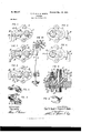
- FIGS. 1, 2, and 3 are front elevations of the igniter, showing its hammer in its three 40 critical positions.
- Fig. 4 is a rear elevation showing the position of the contacts or electrical terminals corresponding to the position of the hammer in Fig. 1.
- Fig. 5 is a similar view showing the positions of the contacts 5 corresponding to the positions of the ham mer in Figs. 2 and 3.
- Fig. 6 is a horizontal section cut on the line 6 6 of Fig. 5 and showing the'engine-frame or cylinder-wall in fragmentary section.
- Figs. 7, 8, and 9 are detail views of'the hammer, the movable contact member, and the spring, respectively; and
- Fig. 10 is a fragmentary front elevation on a smaller scale, showing the operating means.
- the wall or frame of an engine and c the operating mechanism for the igniter.
- A represents the main frame of the igniter, which is attached to the cylinder B and carries all the working parts of theigniter, so that the sparking contacts shall project within a place where ignition is desired, usually inside the cylinder, and the operating mechanism shall be exposed outside where'convenient for access and for engagement with the lifter or other means for operating the igniter.
- O andD are the fixed and movable contacts, respectively, the latter being fixed on a shaft E, which carries an arm Fon its outer end, held thereon by a pin, as shown. Laterally from the arm F is a shoulder G, and journaled on the shaft at a point opposite the shoulder Gis aweight 0r hammer H.
- Aspring K passes around the shaft E and bears against the upper side of the hammer H and the under side of the shoulder G with a pressure of its ends inward against these parts, tending to hold them together.
- a stop L Projecting outward from the frame A is a stop L, shown as a lug formed integrally with the frame, at such a point that when the hammer H rests on it and the arm F is held up by the spring the contacts 0 and D will be slightly separated, as shown in full lines in Fig. 4.
- M represents the lifter, which may be operated by the engine in any well-known manner, its function being to lift the weight H slowly to a predetermined point and then to move laterally out of the path of the weight and permit the latter to fall, the lifter returning to a position under the weight and lifting again at each stroke.
- the frame A is preferably a single metal piece-having a wide body or flange d for fitting against the Wall B, a neck or projection e for fitting into the hole f in the Wall B, a bore g for receiving the pin 77. of the contact 0, a bore '1: for receiving the shaft E, sockets 7' at each end of the bore g, and means for fas- Projecting v tening the frame to the cylinder, as screwholes It, traversed by screws Z for engaging the wall of the cylinder and clamping the igniter thereto, with a leak-tight joint.
- the contact is carried on the pin h, which is insulated from the frame A by insulating-rings m, surrounding the pin and seated in the sockets j.
- the outer end of the pin is screwthreaded, so that. the pin may be clamped tightly in position by nuts n.
- Electrical connections may be made with the pin it and the frame A in any suitable manner, as by the wires 0 p. (Shown in Fig. 10.)
- the shaftE is shown of such length that there is room for the hammer H between the inner face of the arm F and the outer face of the frame A, so that the hammer is retained in position by the arm.
- the operating mechanism 0 consists of a sliding bar a, carrying on its upper end the lifter m and adapted to be operated by any suitable movingpart of an engine--as, forenample,the cam swhich bar maybe suitably guided, as by the gnideway t, and pressed toward the position for engaging the hammer yieldingly, as by the spring a, the bar being operated to throw it from the hammer by a cam-face c, which comes in contact with an adjustable cam-disk w, fulcrumed at m and locked in any position of adjustment bya screw-clamp y. Adjusting the cam w forces the slide 1' away from the axis of the hammer,
- the time of ignition may be regulated by the angular position in which the cam s is set on its shaft. This is a simple, strong, and easily-adjusted operator for igniters, which can be readily applied to any igniter or used with any engine.
- the lifter M is then moved laterally, and the weight of H and the action of the spring K, acting together,cause the hammer to fall with a quick stroke, first to the position of Fig. 2, at which point the separation of the contact-s commences, and then to the position of Fig. 1, at which point the contacts are their normal distance apart.
- the hammet 11 is held from further movement by the anvilL; but the arm F is free to continue its movement a little farther until stopped by the gradual action of the spring, carrying with it in this movement the contact .D a certain distance beyond the normal point of separation and allowing its movement to be stopped slowly and without shock.
- the anvil L will thus take up the shock of the ham mer-blow, so that the minimum of shock consistent with a quick separation of the contacts will be sustained by the working parts other than the hammer and anvil, and these can be of such strength and simplicity as to be proof against injury from the successive blows.
- Adjustment of the cam w to regulate the operation of the lifter M can be quickly made by releasing the clamp-screw y and setting the cam around its axis to the desired point for efiecting the throw-off at the time desired, whereupon the cam can be locked by setting the elamp-screw.
- the igniter constitutes an improved attachment, comprising the frame, the contacts, and contact-operating devices, ready to be applied to any engine.
- This attachment can be shipped ready for use, there is no danger of loss or disarrangement of the parts, and it can beapplied or removed by simple manipulation of the attachingscrews Z, which operation makes it possible for one to immediately get access to the contacts for inspection or repair and to assure the correct relation of all the parts before their application to the cylinder-wall.
- the various parts of the igniter and its operating mechanism constitute improved devices which can be readily and advantageously used for igniters and analogous devices whether or not they are combined with each other in the manner shown as constituting the preferred form of this invention.
- the improved frame A adapted to be attached to the Wall of a cylinder, and having a provision for carrying the shaft of a movable contact, and on opposite sides thereof a stopfor receiving the shock incident to the operation'ofthe mechanism, and a pros vision for carrying the fixed contact.
- the improved frame A adapted to be attached to the wall of a cylinder, a movable contact, a shaft for said movable contact carried by said frame, an anvil for receiving the shock incident to the op-, eration of the mechanism, and a fixed con tact, said anvil and fixed contact being carried by said frame on opposite sides of said shaft.
- the improved frame A adapted to be attached to the wall of a cylinder, a movable c0ntact,-'a shaft for said movable contact carried by' saidframe, an arm on said shaft, a hammer journaled on said shaft, connected'bya spring to said arm and extending beyond said-arm, an anvillon' said frame beyond said arm for receiving the: blow of said hammer, and a fixed contact,- said anvil and fixed contact being carried by said frame on opposite sides of'said shaft.
- lifter M means for operating the same to lift said hammer, and means for moving the same outof'the path-of said hammer whereby the blow of said hammer is received upon saidanvil without shock to the movable parts of the engine.
Landscapes
- Percussive Tools And Related Accessories (AREA)
Description
No; 696,l47 Patented Mar. \25, 1902.:
c. 0. ma A. RIOTTE. IGNITER.
(Application filed Dec. 2, 1899.)
(No Model.)
INVENTFORIS; $1 5M Qy yJ-M WITNESSES:
V UNITED STATES PATENT OFFICE.
CARL O. RIOTTE AND EUGENE A. RIOTTE, OF NEW YORK, N. Y., ASSIGNORS, BY IWIESNE ASSIGNMENTS, TO U. S. LONG DISTANCE AUTOMOBILE COM- PANY, OF ELIZABETH, NEIV JERSEY, A CORPORATION OF NEW JERSEY.
IGNITER.
SPECIFICATION forming part Of Letters lPatent N0. 696,147, dated March 25, 1902.
Application filed December 2, 1899. Serial No. 738,959. (No model.)
To ctZZ whom it may concern:
Be it known that we, CARL O. RIOTTE and EUGENE A. .RIOTTE, citizens of the United States, and residents of the city, county, and
5 State of New York, have jointly invented certain new and useful Improvements in Igniters, of which the following is a specification.
This invention relates to igniters for explosion-engines and to similar devices, and
to aims to provide an improved device espe cially applicable for use as a circuit-breaker or open-circuit igniter for gas, gasolene, or vapor engines.
In igniters it has been difficult to obtain I5 a quick blow for separating the contacts.
Trouble has been found in arresting the motion of the rapidly-moving parts, and the construction has not been as simple, cheap, and durable as is desirable for some uses.
Ourinvention aims to provide for a quick blow and to avoid danger of injury or wear by reason of the impact or sudden stoppage of the moving part, to simplify the construction of the igniter, to provide an improved 25 attachment comprising in itself a complete igniter adapted to readyapplication to or removal'from an engine, to provide improved operating means for an igniter, and toprovide improved details of construction constituting articles of manufacture useful for igniters and other devices in which a quick action is desirable. To this end we provide certain improvements, which will be hereinafter fully set forth.
In the accompanying drawings, which illustrate the preferred form of our improvements as applied to an igniter for an explosion-engine, Figures 1, 2, and 3 are front elevations of the igniter, showing its hammer in its three 40 critical positions. Fig. 4 is a rear elevation showing the position of the contacts or electrical terminals corresponding to the position of the hammer in Fig. 1. Fig. 5 is a similar view showing the positions of the contacts 5 corresponding to the positions of the ham mer in Figs. 2 and 3. Fig. 6 is a horizontal section cut on the line 6 6 of Fig. 5 and showing the'engine-frame or cylinder-wall in fragmentary section. Figs. 7, 8, and 9 are detail views of'the hammer, the movable contact member, and the spring, respectively; and
Fig. 10 is a fragmentary front elevation on a smaller scale, showing the operating means.
Referring to the drawings, Ct indicates the improved igniter attachment as a whole, I)
the wall or frame of an engine, and c the operating mechanism for the igniter.
. In the form of our improved igniter shown, A represents the main frame of the igniter, which is attached to the cylinder B and carries all the working parts of theigniter, so that the sparking contacts shall project within a place where ignition is desired, usually inside the cylinder, and the operating mechanism shall be exposed outside where'convenient for access and for engagement with the lifter or other means for operating the igniter.
O andD are the fixed and movable contacts, respectively, the latter being fixed on a shaft E, which carries an arm Fon its outer end, held thereon by a pin, as shown. laterally from the arm F is a shoulder G, and journaled on the shaft at a point opposite the shoulder Gis aweight 0r hammer H. Aspring K passes around the shaft E and bears against the upper side of the hammer H and the under side of the shoulder G with a pressure of its ends inward against these parts, tending to hold them together.
Projecting outward from the frame A is a stop L, shown as a lug formed integrally with the frame, at such a point that when the hammer H rests on it and the arm F is held up by the spring the contacts 0 and D will be slightly separated, as shown in full lines in Fig. 4.
M represents the lifter, which may be operated by the engine in any well-known manner, its function being to lift the weight H slowly to a predetermined point and then to move laterally out of the path of the weight and permit the latter to fall, the lifter returning to a position under the weight and lifting again at each stroke.
The frame A is preferably a single metal piece-having a wide body or flange d for fitting against the Wall B, a neck or projection e for fitting into the hole f in the Wall B, a bore g for receiving the pin 77. of the contact 0, a bore '1: for receiving the shaft E, sockets 7' at each end of the bore g, and means for fas- Projecting v tening the frame to the cylinder, as screwholes It, traversed by screws Z for engaging the wall of the cylinder and clamping the igniter thereto, with a leak-tight joint. The contact is carried on the pin h, which is insulated from the frame A by insulating-rings m, surrounding the pin and seated in the sockets j. The outer end of the pin is screwthreaded, so that. the pin may be clamped tightly in position by nuts n. Electrical connections may be made with the pin it and the frame A in any suitable manner, as by the wires 0 p. (Shown in Fig. 10.) The shaftE is shown of such length that there is room for the hammer H between the inner face of the arm F and the outer face of the frame A, so that the hammer is retained in position by the arm.
The operating mechanism 0 consists of a sliding bar a, carrying on its upper end the lifter m and adapted to be operated by any suitable movingpart of an engine--as, forenample,the cam swhich bar maybe suitably guided, as by the gnideway t, and pressed toward the position for engaging the hammer yieldingly, as by the spring a, the bar being operated to throw it from the hammer by a cam-face c, which comes in contact with an adjustable cam-disk w, fulcrumed at m and locked in any position of adjustment bya screw-clamp y. Adjusting the cam w forces the slide 1' away from the axis of the hammer,
so that less movement of the slide after itscam-face o strikes the cam in is necessary to throw the slide out until the lifter disengages the hammer, thus insuringanearlier ignition:
or a less forceful drop of the hammer, as desired; or, having adjusted the cam 10 to obtain the desired amount of movement of the hammer, the time of ignition may be regulated by the angular position in which the cam s is set on its shaft. This is a simple, strong, and easily-adjusted operator for igniters, which can be readily applied to any igniter or used with any engine.
In operation,the parts being in the position shown in Fig. 1, the lifter M is brought up under the end of the hammer H, carrying it to the position shown in Fig. 2. This movement has carried the movable contact D from the position shown in Fig. 4 to that shown in Fig. 5, making connection with the fixed contact 0. The further movement of the lifter M carries the hammer to the position of Fig. 3; but the arm F cannot follow it, since the contactB cannot be advanced any farther. This movement of the hammer H therefore results only in producing a greater pressure of contact D on contact 0, and consequently a more intimate degree of connection. The lifter M is then moved laterally, and the weight of H and the action of the spring K, acting together,cause the hammer to fall with a quick stroke, first to the position of Fig. 2, at which point the separation of the contact-s commences, and then to the position of Fig. 1, at which point the contacts are their normal distance apart. At this point the hammet 11 is held from further movement by the anvilL; but the arm F is free to continue its movement a little farther until stopped by the gradual action of the spring, carrying with it in this movement the contact .D a certain distance beyond the normal point of separation and allowing its movement to be stopped slowly and without shock. This greater separation of the contacts contributes to the sudden termination of the spark, and the gradual stoppage of the movement avoids the injuries which are common in igniters of the old type, such as excessive wear and the necessity for frequent readjustment. The anvil L will thus take up the shock of the ham mer-blow, so that the minimum of shock consistent with a quick separation of the contacts will be sustained by the working parts other than the hammer and anvil, and these can be of such strength and simplicity as to be proof against injury from the successive blows. Adjustment of the cam w to regulate the operation of the lifter M can be quickly made by releasing the clamp-screw y and setting the cam around its axis to the desired point for efiecting the throw-off at the time desired, whereupon the cam can be locked by setting the elamp-screw.
It will beseen that the igniter constitutes an improved attachment, comprising the frame, the contacts, and contact-operating devices, ready to be applied to any engine. This attachment can be shipped ready for use, there is no danger of loss or disarrangement of the parts, and it can beapplied or removed by simple manipulation of the attachingscrews Z, which operation makes it possible for one to immediately get access to the contacts for inspection or repair and to assure the correct relation of all the parts before their application to the cylinder-wall. It will also be apparent that the various parts of the igniter and its operating mechanism constitute improved devices which can be readily and advantageously used for igniters and analogous devices whether or not they are combined with each other in the manner shown as constituting the preferred form of this invention.
Our invention can be variously and advantageously availed of, and it willbe understood that we do not limit ourselves to the particular details of construction, arrangement, and
combination set forth as constituting its preferred form, since it can be availed of in whole or in part, according to such modifications as circumstances or the judgment of those skilled in the art may dictate, without departing from the spirit of the invention.
Having described our invention in its preferred form what we claim, and desire to secure by Letters Patent, is-
1. In igniters, the improved frame Aadapted to be attached to the Wall of a cylinder, and having a provision for carrying the shaft of a movable contact, and on opposite sides thereof a stopfor receiving the shock incident to the operation'ofthe mechanism, and a pros vision for carrying the fixed contact.
2. In igniters,in combination,the improved frame A adapted to be attached to the wall of a cylinder, a movable contact, a shaft for said movable contact carried by said frame, an anvil for receiving the shock incident to the op-, eration of the mechanism, and a fixed con tact, said anvil and fixed contact being carried by said frame on opposite sides of said shaft. I
3, In igniters,in combination,the improved frame A adapted to be attached to the wall of a cylinder, a movable c0ntact,-'a shaft for said movable contact carried by' saidframe, an arm on said shaft, a hammer journaled on said shaft, connected'bya spring to said arm and extending beyond said-arm, an anvillon' said frame beyond said arm for receiving the: blow of said hammer, and a fixed contact,- said anvil and fixed contact being carried by said frame on opposite sides of'said shaft.
mer for operating said movable contact, an-
anvil which receives the blow ofsaid hammer, said fixed contact and anvil being carried by said frame on opposite sides of said shaft, a
lifter M, means for operating the same to lift said hammer, and means for moving the same outof'the path-of said hammer whereby the blow of said hammer is received upon saidanvil without shock to the movable parts of the engine.
In witness whereof We have hereunto signed our names in the presenceof two subscribing Witnesses:
Y GEORGE HrFRASER,
THOMAS F. WALLACE.
Priority Applications (1)
| Application Number | Priority Date | Filing Date | Title |
|---|---|---|---|
| US73895999A US696147A (en) | 1899-12-02 | 1899-12-02 | Igniter. |
Applications Claiming Priority (1)
| Application Number | Priority Date | Filing Date | Title |
|---|---|---|---|
| US73895999A US696147A (en) | 1899-12-02 | 1899-12-02 | Igniter. |
Publications (1)
| Publication Number | Publication Date |
|---|---|
| US696147A true US696147A (en) | 1902-03-25 |
Family
ID=2764683
Family Applications (1)
| Application Number | Title | Priority Date | Filing Date |
|---|---|---|---|
| US73895999A Expired - Lifetime US696147A (en) | 1899-12-02 | 1899-12-02 | Igniter. |
Country Status (1)
| Country | Link |
|---|---|
| US (1) | US696147A (en) |
-
1899
- 1899-12-02 US US73895999A patent/US696147A/en not_active Expired - Lifetime
Similar Documents
| Publication | Publication Date | Title |
|---|---|---|
| US696147A (en) | Igniter. | |
| US1206953A (en) | Device for preventing overloading of trucks. | |
| US648122A (en) | Electric igniter for explosive-engines. | |
| US783158A (en) | Sparking igniter for explosive-engines. | |
| US655289A (en) | Igniter for explosive-engines. | |
| US969193A (en) | Governor. | |
| US717902A (en) | Electric igniting device for internal-combustion engines. | |
| US1226114A (en) | Circuit-interrupter. | |
| US706121A (en) | Ignition-gear for internal-combustion engines. | |
| US591598A (en) | Igniter for gas or gasolene engines | |
| US1284461A (en) | Gas-engine starting device. | |
| US750349A (en) | Combined gas controller and igniter for explosive-engines | |
| US1153767A (en) | Igniter mechanism for internal-combustion engines. | |
| US865099A (en) | Engine. | |
| US1185030A (en) | Ignitor for internal-combustion engines. | |
| US646867A (en) | Igniter for gas-engines. | |
| US764998A (en) | Electric igniter for gas-engines. | |
| US956075A (en) | Gas-engine igniter. | |
| US728747A (en) | Electric igniter for hydrocarbon-engines. | |
| US885324A (en) | Sparking mechanism. | |
| US640395A (en) | Gas-engine ignition device. | |
| US737923A (en) | Igniter for gas-engines. | |
| US1106466A (en) | Control-pedal for automobiles. | |
| US1248219A (en) | Igniter for internal-combustion engines. | |
| USRE12957E (en) | Po web |