US6955654B2 - Range of motion walker boot - Google Patents
Range of motion walker boot Download PDFInfo
- Publication number
- US6955654B2 US6955654B2 US10/378,897 US37889703A US6955654B2 US 6955654 B2 US6955654 B2 US 6955654B2 US 37889703 A US37889703 A US 37889703A US 6955654 B2 US6955654 B2 US 6955654B2
- Authority
- US
- United States
- Prior art keywords
- range
- motion device
- motion
- annular
- engageable
- Prior art date
- Legal status (The legal status is an assumption and is not a legal conclusion. Google has not performed a legal analysis and makes no representation as to the accuracy of the status listed.)
- Expired - Lifetime
Links
- 239000000463 material Substances 0.000 claims description 5
- 238000010276 construction Methods 0.000 description 13
- 241001272996 Polyphylla fullo Species 0.000 description 6
- 230000007246 mechanism Effects 0.000 description 5
- 210000002683 foot Anatomy 0.000 description 4
- 210000003423 ankle Anatomy 0.000 description 3
- 210000000544 articulatio talocruralis Anatomy 0.000 description 2
- 238000000465 moulding Methods 0.000 description 2
- 230000000694 effects Effects 0.000 description 1
- 210000001699 lower leg Anatomy 0.000 description 1
- 239000002184 metal Substances 0.000 description 1
- 238000000926 separation method Methods 0.000 description 1
- 210000002105 tongue Anatomy 0.000 description 1
Images


Classifications
-
- A—HUMAN NECESSITIES
- A61—MEDICAL OR VETERINARY SCIENCE; HYGIENE
- A61F—FILTERS IMPLANTABLE INTO BLOOD VESSELS; PROSTHESES; DEVICES PROVIDING PATENCY TO, OR PREVENTING COLLAPSING OF, TUBULAR STRUCTURES OF THE BODY, e.g. STENTS; ORTHOPAEDIC, NURSING OR CONTRACEPTIVE DEVICES; FOMENTATION; TREATMENT OR PROTECTION OF EYES OR EARS; BANDAGES, DRESSINGS OR ABSORBENT PADS; FIRST-AID KITS
- A61F5/00—Orthopaedic methods or devices for non-surgical treatment of bones or joints; Nursing devices; Anti-rape devices
- A61F5/01—Orthopaedic devices, e.g. splints, casts or braces
- A61F5/0102—Orthopaedic devices, e.g. splints, casts or braces specially adapted for correcting deformities of the limbs or for supporting them; Ortheses, e.g. with articulations
- A61F5/0127—Orthopaedic devices, e.g. splints, casts or braces specially adapted for correcting deformities of the limbs or for supporting them; Ortheses, e.g. with articulations for the feet
-
- A—HUMAN NECESSITIES
- A61—MEDICAL OR VETERINARY SCIENCE; HYGIENE
- A61F—FILTERS IMPLANTABLE INTO BLOOD VESSELS; PROSTHESES; DEVICES PROVIDING PATENCY TO, OR PREVENTING COLLAPSING OF, TUBULAR STRUCTURES OF THE BODY, e.g. STENTS; ORTHOPAEDIC, NURSING OR CONTRACEPTIVE DEVICES; FOMENTATION; TREATMENT OR PROTECTION OF EYES OR EARS; BANDAGES, DRESSINGS OR ABSORBENT PADS; FIRST-AID KITS
- A61F5/00—Orthopaedic methods or devices for non-surgical treatment of bones or joints; Nursing devices; Anti-rape devices
- A61F5/01—Orthopaedic devices, e.g. splints, casts or braces
- A61F5/0102—Orthopaedic devices, e.g. splints, casts or braces specially adapted for correcting deformities of the limbs or for supporting them; Ortheses, e.g. with articulations
- A61F2005/0132—Additional features of the articulation
- A61F2005/0137—Additional features of the articulation with two parallel pivots
- A61F2005/0139—Additional features of the articulation with two parallel pivots geared
-
- A—HUMAN NECESSITIES
- A61—MEDICAL OR VETERINARY SCIENCE; HYGIENE
- A61F—FILTERS IMPLANTABLE INTO BLOOD VESSELS; PROSTHESES; DEVICES PROVIDING PATENCY TO, OR PREVENTING COLLAPSING OF, TUBULAR STRUCTURES OF THE BODY, e.g. STENTS; ORTHOPAEDIC, NURSING OR CONTRACEPTIVE DEVICES; FOMENTATION; TREATMENT OR PROTECTION OF EYES OR EARS; BANDAGES, DRESSINGS OR ABSORBENT PADS; FIRST-AID KITS
- A61F5/00—Orthopaedic methods or devices for non-surgical treatment of bones or joints; Nursing devices; Anti-rape devices
- A61F5/01—Orthopaedic devices, e.g. splints, casts or braces
- A61F5/0102—Orthopaedic devices, e.g. splints, casts or braces specially adapted for correcting deformities of the limbs or for supporting them; Ortheses, e.g. with articulations
- A61F2005/0132—Additional features of the articulation
- A61F2005/0165—Additional features of the articulation with limits of movement
- A61F2005/0167—Additional features of the articulation with limits of movement adjustable
Definitions
- This invention relates to a range of motion device and has been devised particularly, though not necessarily solely, for use with an orthopaedic walker.
- Walkers are used as immobilisation and support structures for the lower leg and ankle. Walkers are devices for the immobilisation and protection of the lower leg, ankle and foot. Walkers typically consist of a shoe or chassis which is strapped to the patient's foot, and arms or uprights which are strapped to the lower leg. These uprights can either be fixed at 90° to the ground or there can be provision for the uprights to be fixed in a range of positions or pass through a range of permissible ankle movement. The majority of the market is for walkers with a fixed upright. A smaller percentage is for walkers providing a range of fixed positions, and/or alternatively a series of ranges of motion for the uprights.
- a fixed walker has the upright set at 90° to the ground. Commonly the requirement is for a range of fixed positions between 30° of plantar flexion and 30° of dorsiflexion. Plantar flexion refers to downward movement of the foot at the ankle joint, while dorsiflexion refers to upward motion of the foot from the ankle joint.
- a range of motion which may be anywhere within a usual range of plus 30° (plantar flexion) to minus 30° (dorsiflexion). It is preferable to provide for settings in 5° increments.
- the current art consists of a collection of metal mechanisms where stops or pins are moved to limit motion in either direction.
- Range of motion mechanisms particularly for use with orthopaedic walkers, as presently available, therefore have some limitations.
- the invention consists in a range of motion device for use between a first member and a second member, rotatable connection between the first member and the second member, a range of motion limiting means engageable on the first member and acting on the second member to limit the range of rotational movement of the second member relative to the first member.
- the rotatable connection means comprises an aperture through the first member and a trunnion on the second member positionable in the aperture in the first member.
- a substantially annular member surrounds the aperture and the range of motion limiting means is engageable on the substantially annular member.
- the range of motion limiting means comprise a pair of further annular members each having an outward protrusion, the pair of members being engageable on the annular protrusion at selected ones of a plurality of allowable positions so that the distance between the outward protrusions can be varied so as to alter the maximum range of movement of the second member relative to the first member.
- annular protrusion has outwardly facing splines and each further annular member has inwardly facing splines engageable onto the outwardly facing splines.
- annular member having inward splines engageable onto the outwardly facing splines on the annular member.
- the second member has a detent thereon positionable in the space between the outwardly extending protrusions.
- lock means are provided to hold the first member the second member and the further annular members in engagement.
- the lock means comprise a plate with a protrusion thereon and means to engage that protrusion with the trunnion.
- the lock means further include a bore in, or protrusion on, the plate to engage the trunnion.
- lock means are provided to engage the plate with the first member.
- the further lock means comprise slots about the annular protrusion and hook members on the plate engageable into the slots in a rotatable manner to engage the hook members with material surrounding the slots.
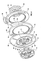
- FIG. 1 is a perspective view of a walker having a range of motion device according to a preferred form of the invention shown in exploded form,
- FIG. 2 is a perspective view of a plate forming part of the range of motion device shown in FIG. 1 ,
- FIG. 3 is a side elevation of the plate of FIG. 2 .
- FIG. 4 is an exploded perspective view of parts of an alternative range of motion device according to the invention.
- FIG. 5 is an exploded perspective view as in FIG. 4 , but from the opposite hand.
- a range of motion device particularly to provide a control mechanism for an orthopaedic walker is provided as follows.
- a first member 1 is provided which may comprise part of an orthopaedic walker shoe 2 .
- the shoe 2 has an upstanding part 3 there being one upstanding part 3 positioned to each side of the shoe. Accordingly a pair of first members I are provided. If desired an alternative construction which provides only a single range of motion device on the shoe can be provided.
- a second member which, in the preferred form, comprises an arm 4 which in use will extend up the lower leg of a user and allow the arm to be bound to the user's leg(s), for example, by passing straps or the like through apertures 5 in the arm 4 .
- An aperture 10 is provided in the first member and this is surrounded preferably on the outwardly facing face with an annular protrusion 11 .
- the annular protrusion 11 can be integrally moulded with shoe 2 or could be affixed, for example, by plugging into an aperture.
- Such a construction has some advantages, firstly the shoe 2 is a large moulding, but protrusion 21 requires precision and making the construction in two parts aids satisfaction of these two factors. Secondly moulding in separate pieces allows different materials to be used and thirdly alternative mechanisms can be placed in the ‘plug-in’ aperture.
- a trunnion 12 which is preferably castellated is provided on the arm 4 , the trunnion being able to pass through the aperture 10 so as to be a rotatable fit therein.
- ends of the arms forming the castellated trunnion may have an outwardly extending lip 13 which becomes positionable in a rebate 14 in the annular protrusion 11 , for example, by being a “snap” fit therein, but still allowing the above-mentioned rotation.
- Range of motion limiting means are provided to limit the rotation of the arm 4 with respect to the first member 1 .
- this may take the form of a pair of further annular members 20 and 21 each of which has an outwardly extending protrusions 23 and 24 thereon.
- a substantially radial faces 25 and 26 is provided on the extending protrusions 23 and 24 .
- the further annular members 20 and 21 are positionable onto the annular protrusion 11 in a manner such that a gap is formed between the outwardly extending protrusions 23 and 24 and more particularly between the radial faces 25 and 26 which are arranged to be mutually inwardly facing.
- Means are provided to enable the separation of the radial faces 25 and 26 to be varied and in the preferred form this may take the form of outwardly extending splines 30 on the annular member 11 and co-operating inwardly extending splines 31 and 32 on the further annular members 20 and 21 .
- the thickness of the annular members 20 and 21 is less and preferably about half of the thickness of the annular protrusion 11 .
- the distance apart of the radial faces 25 and 26 can be readily varied by altering the position of engagement with the co-operating splines 30 and 31 and 30 and 32 .
- the arm 4 is provided with a detent 40 which extends across the first member 1 and is able, in use, to be positioned between the faces 25 and 26 . If the faces 25 and 26 are positioned so that they abut the edges of the detent 40 , only a relatively small range of motion of the arm 4 , with respect to the first member 1 , will be achieved but if the gap is larger a more substantial range of motion is provided.
- the splints are arranged such that the space can be increased in 5° steps, although any suitable size of step may be provided.
- Lock means are provided to lock the construction together and to this end an end plate 50 is provided which has inwardly extending protrusion 51 which again may have a degree of castellation and an outwardly extending lip 52 .
- the protrusion 51 in use, becomes positioned within the trunnion 12 which may have a rebate at 53 over which the lip 52 is a “snap” fit.
- the plate is also desirably provided with a further lock means to engage the first member 1 and this may be achieved by providing a number of depressions such as 3 at 60 in the outwardly facing splined face of the annular protrusion 11 and providing slots 61 in that space.
- the plate 50 is provided with a number of arms 63 which are provided with a hook 64 at the ends thereof. The dimensions of the arms and hooks are such that the arm 63 and hook 64 may pass through the slots 61 allowing the plate to be rotated into its desired position in a manner such that the hooks 64 catch behind the material about the slots 61 .
- the plate 50 can be rotated so that the hooks 64 become free and the plate can then be forced so that the protrusion 51 becomes free of the trunnion 12 .
- the annular members 20 and 21 can then be moved to a new position and the construction reassembled with the range of motion of the arm 4 relative to the member 1 being varied.
- a further annular member may be provided which is in effect a combination of the members 20 and 21 which will be able to be positioned on the annular protrusion 11 so as to provide a fixed range of motion.
- the exact position over which the range of motion, if any, provided can be varied. Of course in most instances such a member would provide a zero range of motion to the arm 4 .
- a trunnion 12 is again provided on arm 4 .
- end plate 50 is replaced by a pair of plates comprising the end plate 50 and a cap member 74 .
- the end plate 50 has inwardly extending pins 71 which are positioned in the slots 70 . This restricts rotation of two annular members 20 and 21 and in particular prevents the protrusions 23 and 24 from crossing.
- the end plate 50 has a central aperture 72 and apertures 73 of which, in the embodiments shown, there are three such apertures 73 spaced thereabout.
- the cap member 74 has a central spigot 75 with outwardly extending lips 76 thereon substantially as for the lips 52 of the previous invention.
- the spigot 75 is attached to the cap part 77 .
- the plate 50 also has a spigot 85 with a central bore 86 ,
- the spigot 85 is provided with slots 87 therein and a rebate 88 is provided on each castellation formed by slots 87 .
- the spigot 75 passes through the apertures 72 in the end plate 50 and through the spigot 85 .
- the end plate 50 and cap member 74 are rotated one relative to the other so that extending lips 76 enter the rebates 88 .
- the spigot 75 causes the castellations to spread (either the spigot 75 or bore of spigot 85 may be tapered.
- the end plate 50 may be also shaped to provide resilient protrusions 80 which bear upon the inner surface of the end cap member 74 .
- the end plate 50 also is provided with tongues 90 which in use are positioned as for the previous embodiment.
- the distal end 94 of spigot 85 has raised ridges 95 thereon which engage in a groove or rebate 96 in the bore of trunnion 12 to hold the construction when assembled loosely in place.
- the ridges enter a further groove 97 .
- Pushing spigot 75 into the bore of spigot 85 causes spigot 85 to spread which and pushes the raised ridges 95 further into groove 97 .
- the construction can be disassembled by rotation of the cap 74 relative to end plate 50 until the outwardly extending lips 76 clear the rebates 88 .
- the resilient protrusions 80 will push the cap 74 away from the end plate 50 allowing cap 74 to be gripped and removed so that the raised ridges 95 clear the groove 97 (or at least are easily removed).
- the range of motion device is assembled as above described and the distance between the radial faces 25 and 26 set to achieve the range of motion required by, for example, the orthopaedic surgeon.
- the range of motion can be altered.
- a range of motion device which will operate as a control mechanism particularly, though not necessarily solely, for an orthopaedic walker.
Abstract
Description
Claims (16)
Applications Claiming Priority (2)
| Application Number | Priority Date | Filing Date | Title |
|---|---|---|---|
| NZ51759402 | 2002-03-05 | ||
| NZ517594 | 2002-03-05 |
Publications (2)
| Publication Number | Publication Date |
|---|---|
| US20030199798A1 US20030199798A1 (en) | 2003-10-23 |
| US6955654B2 true US6955654B2 (en) | 2005-10-18 |
Family
ID=29208856
Family Applications (1)
| Application Number | Title | Priority Date | Filing Date |
|---|---|---|---|
| US10/378,897 Expired - Lifetime US6955654B2 (en) | 2002-03-05 | 2003-03-05 | Range of motion walker boot |
Country Status (1)
| Country | Link |
|---|---|
| US (1) | US6955654B2 (en) |
Cited By (15)
| Publication number | Priority date | Publication date | Assignee | Title |
|---|---|---|---|---|
| US7524295B1 (en) * | 2007-06-25 | 2009-04-28 | Ultra Athlete Llc | Convertible ankle brace |
| US20100069807A1 (en) * | 2008-09-17 | 2010-03-18 | Cox William J | Orthotic device with sliding mechanism |
| US20130345613A1 (en) * | 2012-06-20 | 2013-12-26 | Ultra Athlete Llc | Ankle brace including a snap-together pivoting upper extension shell |
| US20140034068A1 (en) * | 2012-08-06 | 2014-02-06 | Thomas J. Picar | Configurable orthopedic device |
| US20140135675A1 (en) * | 2012-11-12 | 2014-05-15 | Terry M. Nayfa | Ankle Brace |
| US9248042B2 (en) | 2012-09-12 | 2016-02-02 | Yessenia Lopez | Dorsal foot splint |
| US9492305B2 (en) | 2013-03-15 | 2016-11-15 | Ortho Systems | Orthopedic walking boot with heel cushion |
| US9510965B2 (en) | 2014-07-01 | 2016-12-06 | Ortho Systems | Adjustable walking apparatus |
| US20170216072A1 (en) * | 2016-02-02 | 2017-08-03 | Tung-Cheng Chen | Ankle stirrup |
| US9770357B2 (en) | 2012-11-12 | 2017-09-26 | Terry M. Nayfa | Ankle brace |
| US10039664B2 (en) | 2013-03-15 | 2018-08-07 | Ortho Systems | Overmolding for an orthopedic walking boot |
| USD846130S1 (en) | 2018-01-31 | 2019-04-16 | Ortho Systems | Knee brace |
| US10449078B2 (en) | 2013-03-15 | 2019-10-22 | Ovation Medical | Modular system for an orthopedic walking boot |
| US10863791B2 (en) | 2011-04-07 | 2020-12-15 | Ovation Medical | Removable leg walker |
| EP4197515A4 (en) * | 2020-09-27 | 2024-01-24 | Shanghai Fourier Intelligence Co Ltd | Ankle joint device having adjustable foot support initial angle |
Families Citing this family (5)
| Publication number | Priority date | Publication date | Assignee | Title |
|---|---|---|---|---|
| ITMI20040574A1 (en) * | 2004-03-24 | 2004-06-24 | Orthoscharer & Co Di Paolo Ros | ARTICULATED AUCTION WITH ASSISTED ADJUSTMENT FOR AN ORTHOPEDIC GUARDIAN |
| US20070043314A1 (en) * | 2005-08-19 | 2007-02-22 | Restorative Care Of America Incorporated | Abduction hinge for a hip stabilizer |
| EP2136665A4 (en) | 2007-04-26 | 2011-11-23 | Ossur Hf | Orthopedic shoe providing access to wound site |
| CN101827568A (en) * | 2007-10-15 | 2010-09-08 | 奥索集团公司 | Orthopedic device having a patient compliance system |
| US10085870B2 (en) * | 2015-06-22 | 2018-10-02 | Horsepower Technologies Inc. | Joint brace with improved range of motion stop |
Citations (9)
| Publication number | Priority date | Publication date | Assignee | Title |
|---|---|---|---|---|
| US5269748A (en) * | 1970-11-04 | 1993-12-14 | Restorative Care Of America Incorporated | Therapeutic leg and foot device |
| US5429588A (en) * | 1993-02-17 | 1995-07-04 | Innovative Care Ltd. | Ankle foot orthoses known as lower leg walkers |
| US5954075A (en) * | 1996-12-03 | 1999-09-21 | Bodyworks Healthcare Limited | Walker |
| US6024713A (en) * | 1998-12-17 | 2000-02-15 | Barney; George Melvin | Leg support apparatus |
| US6155998A (en) * | 1997-12-03 | 2000-12-05 | Bodyworks Properties Limited | Walker |
| US6394117B1 (en) * | 1998-09-23 | 2002-05-28 | Bodyworks Properties Limited | Plug for connecting to a walker |
| US6656145B1 (en) * | 1998-01-30 | 2003-12-02 | Active Ankle Systems, Inc. | Ankle brace with removable single piece hinge |
| US6749578B2 (en) * | 1999-02-18 | 2004-06-15 | Athlete Protection Gear, Llc | Ankle brace with cuff and strap |
| US6764457B2 (en) * | 2001-04-27 | 2004-07-20 | Hogg Theodore B | Leg brace support structure |
-
2003
- 2003-03-05 US US10/378,897 patent/US6955654B2/en not_active Expired - Lifetime
Patent Citations (11)
| Publication number | Priority date | Publication date | Assignee | Title |
|---|---|---|---|---|
| US5269748A (en) * | 1970-11-04 | 1993-12-14 | Restorative Care Of America Incorporated | Therapeutic leg and foot device |
| US5269748B1 (en) * | 1970-11-04 | 1998-07-07 | Restorative Care Of America In | Therapeutic leg and foot device |
| US5429588A (en) * | 1993-02-17 | 1995-07-04 | Innovative Care Ltd. | Ankle foot orthoses known as lower leg walkers |
| US5954075A (en) * | 1996-12-03 | 1999-09-21 | Bodyworks Healthcare Limited | Walker |
| US6155998A (en) * | 1997-12-03 | 2000-12-05 | Bodyworks Properties Limited | Walker |
| US6361515B1 (en) * | 1997-12-03 | 2002-03-26 | Bodyworks Properties Limited | Walker |
| US6656145B1 (en) * | 1998-01-30 | 2003-12-02 | Active Ankle Systems, Inc. | Ankle brace with removable single piece hinge |
| US6394117B1 (en) * | 1998-09-23 | 2002-05-28 | Bodyworks Properties Limited | Plug for connecting to a walker |
| US6024713A (en) * | 1998-12-17 | 2000-02-15 | Barney; George Melvin | Leg support apparatus |
| US6749578B2 (en) * | 1999-02-18 | 2004-06-15 | Athlete Protection Gear, Llc | Ankle brace with cuff and strap |
| US6764457B2 (en) * | 2001-04-27 | 2004-07-20 | Hogg Theodore B | Leg brace support structure |
Cited By (20)
| Publication number | Priority date | Publication date | Assignee | Title |
|---|---|---|---|---|
| US7524295B1 (en) * | 2007-06-25 | 2009-04-28 | Ultra Athlete Llc | Convertible ankle brace |
| US20100069807A1 (en) * | 2008-09-17 | 2010-03-18 | Cox William J | Orthotic device with sliding mechanism |
| US8313451B2 (en) * | 2008-09-17 | 2012-11-20 | Cox William J | Orthotic device with sliding mechanism |
| US10863791B2 (en) | 2011-04-07 | 2020-12-15 | Ovation Medical | Removable leg walker |
| US20130345613A1 (en) * | 2012-06-20 | 2013-12-26 | Ultra Athlete Llc | Ankle brace including a snap-together pivoting upper extension shell |
| US9186269B2 (en) * | 2012-06-20 | 2015-11-17 | Ultra Athlete Llc | Ankle brace including a snap-together pivoting upper extension shell |
| US20140034068A1 (en) * | 2012-08-06 | 2014-02-06 | Thomas J. Picar | Configurable orthopedic device |
| US9248042B2 (en) | 2012-09-12 | 2016-02-02 | Yessenia Lopez | Dorsal foot splint |
| US9775736B2 (en) * | 2012-11-12 | 2017-10-03 | Terry M. Nayfa | Ankle brace |
| US9770357B2 (en) | 2012-11-12 | 2017-09-26 | Terry M. Nayfa | Ankle brace |
| US20140135675A1 (en) * | 2012-11-12 | 2014-05-15 | Terry M. Nayfa | Ankle Brace |
| US9492305B2 (en) | 2013-03-15 | 2016-11-15 | Ortho Systems | Orthopedic walking boot with heel cushion |
| US10449078B2 (en) | 2013-03-15 | 2019-10-22 | Ovation Medical | Modular system for an orthopedic walking boot |
| US10039664B2 (en) | 2013-03-15 | 2018-08-07 | Ortho Systems | Overmolding for an orthopedic walking boot |
| US10085871B2 (en) | 2013-03-15 | 2018-10-02 | Ovation Systems | Overmolding for an orthopedic walking boot |
| US9510965B2 (en) | 2014-07-01 | 2016-12-06 | Ortho Systems | Adjustable walking apparatus |
| US10449077B2 (en) | 2014-07-01 | 2019-10-22 | Ovation Medical | Adjustable walking apparatus |
| US20170216072A1 (en) * | 2016-02-02 | 2017-08-03 | Tung-Cheng Chen | Ankle stirrup |
| USD846130S1 (en) | 2018-01-31 | 2019-04-16 | Ortho Systems | Knee brace |
| EP4197515A4 (en) * | 2020-09-27 | 2024-01-24 | Shanghai Fourier Intelligence Co Ltd | Ankle joint device having adjustable foot support initial angle |
Also Published As
| Publication number | Publication date |
|---|---|
| US20030199798A1 (en) | 2003-10-23 |
Similar Documents
| Publication | Publication Date | Title |
|---|---|---|
| US6955654B2 (en) | Range of motion walker boot | |
| US6203511B1 (en) | Orthotic joint and method | |
| US6419198B1 (en) | CPU supporting assembly | |
| US9132026B2 (en) | Adjustable pad and orthopedic knee brace including same | |
| CN101404961B (en) | Adjustable ergonomic brace | |
| US5101837A (en) | Bandage elevation device | |
| AU722363B2 (en) | An ostomy coupling | |
| JPH0751308A (en) | Hinge assembly for orthesis with detent mechanism | |
| JPH02261448A (en) | Coupling for aritifical anal | |
| PT858781E (en) | ORTHOPEDIC DEVICE FOR THE GRADUAL CORRECTION OF THE MEMBERS | |
| EP2339998A1 (en) | Brace hinge with telescoping condyle pad | |
| US4702443A (en) | Cord holding device | |
| US9770357B2 (en) | Ankle brace | |
| US6244779B1 (en) | Angularly adjustable coupling | |
| NO852021L (en) | IMPROVED LOCKING DEVICE. | |
| GB2133289A (en) | Adjustable abduction splint | |
| RU2506929C2 (en) | Implant | |
| JP5726158B2 (en) | General-purpose dental X-ray sensor holder | |
| US6033373A (en) | Orthopaedic knee brace | |
| JPS6323070Y2 (en) | ||
| AU720589B2 (en) | Orifice coupling | |
| KR20190090996A (en) | adjustable length tripod | |
| JP3826882B2 (en) | Human orthosis | |
| RU2268686C2 (en) | Endoprosthesis of intervertebral disc | |
| JPH0441832Y2 (en) |
Legal Events
| Date | Code | Title | Description |
|---|---|---|---|
| AS | Assignment |
Owner name: BODYWORKS INC., CALIFORNIA Free format text: ASSIGNMENT OF ASSIGNORS INTEREST;ASSIGNOR:GILMOUR, ROBERT FARRER;REEL/FRAME:013773/0137 Effective date: 20030315 |
|
| STCF | Information on status: patent grant |
Free format text: PATENTED CASE |
|
| FPAY | Fee payment |
Year of fee payment: 4 |
|
| AS | Assignment |
Owner name: OMNI LIFE SCIENCE INC., MASSACHUSETTS Free format text: ASSIGNMENT OF ASSIGNORS INTEREST;ASSIGNOR:BODYWORKS, INC.;REEL/FRAME:022634/0955 Effective date: 20090331 |
|
| AS | Assignment |
Owner name: VQ ORTHOCARE, CALIFORNIA Free format text: ASSIGNMENT OF ASSIGNORS INTEREST;ASSIGNOR:OMNI LIFE SCHIENCES, INC.;REEL/FRAME:022678/0823 Effective date: 20090317 |
|
| FPAY | Fee payment |
Year of fee payment: 8 |
|
| FPAY | Fee payment |
Year of fee payment: 12 |