US6915155B2 - Medical testing system with an illuminating component and automatic shut-off - Google Patents
Medical testing system with an illuminating component and automatic shut-off Download PDFInfo
- Publication number
- US6915155B2 US6915155B2 US09/915,672 US91567201A US6915155B2 US 6915155 B2 US6915155 B2 US 6915155B2 US 91567201 A US91567201 A US 91567201A US 6915155 B2 US6915155 B2 US 6915155B2
- Authority
- US
- United States
- Prior art keywords
- keypad
- testing system
- echocardiogram
- illuminating component
- medical testing
- Prior art date
- Legal status (The legal status is an assumption and is not a legal conclusion. Google has not performed a legal analysis and makes no representation as to the accuracy of the status listed.)
- Expired - Fee Related, expires
Links
Images


Classifications
-
- A—HUMAN NECESSITIES
- A61—MEDICAL OR VETERINARY SCIENCE; HYGIENE
- A61B—DIAGNOSIS; SURGERY; IDENTIFICATION
- A61B5/00—Measuring for diagnostic purposes; Identification of persons
- A61B5/24—Detecting, measuring or recording bioelectric or biomagnetic signals of the body or parts thereof
- A61B5/316—Modalities, i.e. specific diagnostic methods
- A61B5/318—Heart-related electrical modalities, e.g. electrocardiography [ECG]
- A61B5/321—Accessories or supplementary instruments therefor, e.g. cord hangers
-
- A—HUMAN NECESSITIES
- A61—MEDICAL OR VETERINARY SCIENCE; HYGIENE
- A61B—DIAGNOSIS; SURGERY; IDENTIFICATION
- A61B5/00—Measuring for diagnostic purposes; Identification of persons
- A61B5/24—Detecting, measuring or recording bioelectric or biomagnetic signals of the body or parts thereof
- A61B5/316—Modalities, i.e. specific diagnostic methods
- A61B5/318—Heart-related electrical modalities, e.g. electrocardiography [ECG]
- A61B5/329—Load diagnosis, e.g. cardiac stress tests
-
- A—HUMAN NECESSITIES
- A61—MEDICAL OR VETERINARY SCIENCE; HYGIENE
- A61B—DIAGNOSIS; SURGERY; IDENTIFICATION
- A61B2560/00—Constructional details of operational features of apparatus; Accessories for medical measuring apparatus
- A61B2560/04—Constructional details of apparatus
- A61B2560/0437—Trolley or cart-type apparatus
Definitions
- the field of the invention generally relates to a medical testing system, and more particularly, to a medical testing system with an illuminating component.
- Heart disease is the leading cause of death in the U.S. Heart disease is any condition that causes your heart to malfunction.
- heart disease usually refers to coronary heart disease which leads to heart attacks and angina, ultimately caused by atherosclerosis.
- diseases of the heart such as congestive heart failure, valvular heart disease, diseases of the heart valves, cardiac arrhythmias, i.e., irregular heartbeats, diseases of the pericardium (sac around the heart), diseases of the myocardium (heart muscle), endocarditis (infection of a heart valve), and congenital heart disease, i.e., birth defects of the heart.
- tools that are available to a physician to help monitor and diagnose malfunctions of the heart. They include history and physical examinations, chest x-ray, blood tests, echocardiograms, cardiac catheterizations, electrocardiograms, and EKG stress tests.
- EKG electrocardiogram
- EKG electrocardiogram
- EKG electrocardiogram
- electrodes are usually placed on the arms, legs and chest of a patient. These electrodes are connected by wires to an EKG machine.
- a twelve lead EKG is typically used which generates twelve different tracings or waveforms. Each waveform provides a view of the heart from a different angle.
- These waveforms are stored in memory and if a monitor is used, the waveforms are displayed.
- the waveforms may be recorded on paper by a thermal writer or any other conventional writer.
- a paper roller is driven by a motor that feeds the paper across a heated printer head.
- the physician may view and analyze the waveforms on the paper which moves across a work surface of the EKG machine.
- a physician may be able to determine the location of a heart attack based on the EKG lead involved. Then, based on his/her knowledge of anatomy, the physician may be able to determine which artery is blocked.
- the EKG gives the physician information about heart rate and rhythm, heart blood supply sufficiency, heart attack, heart enlargement, inflammation around the heart, drug effects, and electrolytes on the heart.
- An EKG stress test is another commonly used procedure to evaluate coronary artery disease. It uses a similar EKG machine as described above with electrodes appropriately positioned on a patient to measure the electrical activity of the heart. However, these measurements are taken when the heart is exercised, i.e., “under stress.” EKG stress tests are useful because exercise can reveal abnormalities that were not detected during an EKG of the heart at rest. In this procedure, a person's EKG is initially monitored at rest and then monitored while walking on a treadmill or pedaling a bicycle. The exercise is gradually increased until a target heart rate is reached. If severe EKG changes, chest pain, severe shortness of breath, blood pressure changes or cardiac arrhythmias occur, then the physician may stop the stress test. The EKG stress test may uncover problems with the heart rhythm or blood supply to the heart or may provide valuable planning cardiac rehabilitation after a heart attack or heart surgery.
- An echocardiogram (“echo”) is yet another commonly used procedure to evaluate coronary heart disease.
- the echo uses an ultrasonic beam to view the heart in motion.
- an ultrasonic transducer similar in appearance to a microphone, transmits and receives ultrasonic waves.
- the transducer is placed on the chest wall and maneuvered to view different portions of the heart on a monitor.
- stress echo tests are performed with the room lights dimmed and the sunlight suppressed.
- the echo is used to evaluate the presence of several abnormalities of the heart including (1) abnormal fluid collection in the pericardium, (2) valve obstruction or leaks, (3) chamber size, thickness of heart wall, as well as other problems.
- the EKG and echo stress test procedures are conducted separately at different locations.
- an EKG stress testing system in conjunction with an echo stress testing system at the same location.
- a patient would first undergo an EKG stress test. Immediately following, usually within 10 seconds, but before the patient's heart returns to normal, the patient would quickly move to a resting bed to receive an echo stress test by an echo technician. During this time, the physician continues to evaluate the EKG waveforms which appear on the paper along the work surface of the EKG machine.
- the physician is unable to view, analyze and make appropriate notes on the paper relative to the waveforms with the signals received from the electrodes. If or when the physician is able to complete his analysis of the EKG waveforms, he/she is unable to manipulate the keypads to turn the thermal writer off or control any of the other functions of the EKG machine. In sum, the physician is severely disadvantaged because of the darkness.
- a medical testing system comprising an instrument for monitoring a characteristic of a patient; and an illuminating component for illuminating the instrument, the instrument including: a component for selectively activating and deactivating the illuminating component; and a deactivating component for automatically deactivating the illuminating component, after a predetermined period of time has elapsed.
- a medical testing method comprising the steps of: activating an illuminating component positioned relative to an instrument for monitoring a characteristic of a patient, the instrument including a keypad having a plurality of keys; determining if a key on the plurality of keys has been pressed by a user; and automatically deactivating the illuminating component if a key of the plurality of keys has not been pressed within a predetermined period of time.
- a medical testing system comprising: an instrument for monitoring the electrical activity of a patient's heart; an illuminating component for illuminating the instrument; the instrument including: a component for selectively turning the illuminating component on and off; a component for automatically turning the illuminating component off, after a predetermined period of time has elapsed.
- a computer program for performing a method comprising the steps of: activating an illuminating component positioned relative to an instrument for monitoring a characteristic of a patient, the instrument including a keypad having a plurality of keys; determining if a key on the plurality of keys has been pressed by a user; and automatically deactivating the illuminating component if a key of the plurality of keys has not been pressed within a predetermined period of time.
- a medical testing system comprising: means for monitoring the electrical activity of a patient's heart; means for illuminating the instrument, the instrument including: means for selectively turning the illuminating component on and off; and means for automatically turning the illuminating component off, after a predetermined period of time has elapsed.
- FIG. 1 is a perspective view of the EKG stress testing system which employs a preferred embodiment of the present invention.
- FIG. 2 is a side view of the EKG stress testing system shown in FIG. 1 .
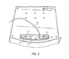
- FIG. 3 is an LED circuit board attached to the bottom of the monitor plate for supporting the monitor shown in FIG. 1 .
- FIG. 4 is a cross-sectional view of the LED circuit board along lines 4 — 4 shown in FIG. 3 .
- FIG. 5 is a block diagram of the components of the EKG stress testing system shown in FIG. 1 .
- FIG. 6 is a flowchart of the program for the implementation for automatic shut off for the LEDs.
- System 10 includes instrument 12 for controlling the entire operation of system 10 , including processing function commands and the signals generated from a plurality of electrodes 14 attached to a patient 16 .
- Each electrode has a corresponding wire of preferably two feet length.
- electrodes 14 are coupled to instrument 12 by way of a cardiology acquisition module 18 and central cable 20 .
- Cable 20 (preferably 20 feet) connects acquisition module 18 to instrument 12 and preferably has a connector with 10-12 pins and locking tabs to ensure that the user properly connects cable 20 to the appropriate port on an acquisition card (discussed below) in the rear of instrument 12 and that cable 20 does not become disconnected during testing.
- Acquisition module 18 functions to convert the analog signal generated from electrodes 14 into digital signals for instrument 12 . This is accomplished by several known components including a digital to analog converter. Acquisition module 18 also includes protection circuitry to protect instrument 12 from receiving high energy jolts from a defibrillator.
- Instrument 12 is mounted in a movable cart 22 for maneuverability and for transporting system 10 from one location to another.
- System 10 includes several operator control devices, similar to that used in for a personal computer, such as keyboard 24 , mouse 26 and monitor 28 . These devices are coupled or connected to the instrument 12 via conventional communication ports that appear in the rear of a computer (video, PS/2, com1), as discussed above.
- keyboard 24 and mouse 26 are conventional components which can be purchased off the shelf.
- Monitor 28 may also be purchased off the shelf.
- the presently preferred embodiment includes particular component circuitry to isolate a monitor's high voltage requirements from a patient to satisfy UL and other power limitation requirements. The isolation circuitry will be discussed in more detail below.
- Monitor 28 is supported by plate 30 .
- Neck 32 is attached underneath to plate 30 and to the rear of instrument 12 .
- Several screws and bolts (six) are used to fasten plate 30 to a flat portion of neck 32 through corresponding holes in each.
- the plate 30 and neck 32 function together to support and position monitor 28 above instrument 12 .
- the height of monitor 28 is fixed relative to instrument 12 .
- Neck 32 is fastened to a bracket in the rear of instrument 12 using nuts which are screwed onto threaded studs on neck 32 .
- the neck or other structure may be designed for adjustment to enable plate 30 to pivot or rotate horizontally with respect to instrument 12 .
- the monitor support structure may be adapted to attach to other surfaces such as a table or desk.
- Instrument 12 also includes a dedicated keypad 34 which includes an elastomer pad, key bezel with keys and printed circuit board combined. In operation, the keys press on the elastomer which has conductive pills that press down on the printed circuit board and close a circuit of copper traces on the printed circuit board. Keypad 34 refers to these components as combined.
- the keys of keypad 34 are located above the area for keyboard 24 .
- Keypad 34 is used to control the treadmill and stress test specific functions. For example, there are preferably keys to control the treadmill such as start/stop, speed and incline keys. There are preferably keys relating to the instructions for the testing part of the procedure (testing phase settings) such as new test, pretest, exercise, recovery, test end, hold/pause, and blood pressure entry. These keys may require personal data input via keyboard 24 . In addition, there are preferably keys relating to report generation and control such as start and stop thermal writer.
- each with a backlight to illuminate the key itself there are 22 keys in total, each with a backlight to illuminate the key itself.
- any number of keys may be employed.
- One key is used to toggle (turn on and off) the light source (illuminating component, discussed below) as well as the backlights for the keys themselves.
- the remaining 21 keys are keys to enable function of the system 10 , as discussed above.
- instrument 12 includes a thermal writer in which a paper roller is driven by a motor that feeds paper 36 across a heated printer head.
- Instrument 12 also includes work surface 38 over which paper record 36 extends. Waveforms generated from electrodes 14 are recorded and printed on paper 36 as it moves through a slot 40 in work surface 38 .
- paper 36 moves across work surface 38 , paper 36 accumulates in a bin 42 attached to moveable cart 22 , located adjacent instrument 12 .
- system 10 also includes an illuminating component (light source) for illuminating work surface 38 and keypad 34 .
- the illuminating component is a circuit board 50 which includes a plurality of light emitting diodes (“LED”) 52 .
- Circuit board 50 is covered by a clear plastic shield 54 which is bolted to and supported by the bottom front end of support plate 30 .
- the LEDs 52 are positioned throughout circuit board 50 . Preferably, 15 white LEDs are used.
- the position of the circuit board 50 together with the number and position of LEDs on circuit board 50 satisfy the following preferred light criteria: (1) the light is properly diffused; (2) minimal glare is produced on paper 36 ; and (3) the light will last a long time.
- the illuminating component preferably illuminates at least three areas or “zones.” These zones are work surface 38 , keypad 34 , located just below work surface 38 , and keyboard 24 . This enables the physician to read and analyze the waveforms on paper 36 (on work surface 38 ) as well as view and manipulate the keys on keypad 34 and keyboard 24 .
- System 10 includes cable 56 which is used to provide power to LED board 50 and LEDs 52 on board 50 . Cable 56 has a connector which is adapted to connect to a port in the interior of instrument 12 . It is important to note that the illuminating component may be of any type and may be positioned anywhere so long as the illuminating component illuminates at least the area in which a physician works on instrument 12 .
- System 10 includes the customary components of a computer such as a master control or motherboard 60 , a CD Read/Write drive 62 , hard drive 64 and floppy drive 66 .
- Master control 60 is used to control the high level operation of system 10 .
- Master control 60 includes the customary components of a computer, such as a microprocessor (CPU), memory (RAM and ROM), and I/O devices.
- the motherboard includes a 566 MHz Intel Celeron microprocessor, 64 MB SDRAM and Windows NT.
- Acquisition card 68 is inserted into a conventional slot on motherboard 60 .
- Acquisition card 68 is used to provide a port for receiving cable 20 and additional ports for other peripheral devices (e.g., treadmill wires, automatic blood pressure devices, pulse oximeters).
- Acquisition module 18 is coupled to acquisition card 68 and electrodes 14 are coupled to acquisition module 18 .
- patient 16 carries acquisition module 18 on his/her waist by a belt.
- Each electrode is attached to patient 16 at different points on his/her body.
- electrodes 14 are preferably attached with “stick on contacts” that a technician sticks to the patient's shaven skin.
- electrodes 14 may be attached to a patient using suction elements that run off a pump.
- the instrument 12 preferably includes a pump so the user has the option to choose either embodiment.
- electrodes 14 are placed on the body in the traditional 12-lead electrode placement, which is a specific pattern across the chest and on all 4 limbs.
- electrodes 14 generate analog signals which are converted by acquisition module 18 into digital signals for acquisition card 68 .
- Instrument 12 includes a power management circuit board 70 for providing power to many of the components in instrument 12 , including monitor 28 .
- a power management circuit board 70 for providing power to many of the components in instrument 12 , including monitor 28 .
- instrument 12 utilizes a separate protection device or isolation transformer 22 to isolate the power supplied to the monitor from patient 16 .
- monitor 28 is used to display many characteristics of the patient and of the procedure including the EKG instrument settings, the treadmill settings, e.g., grade, speed, blood pressure entered, number of leads, etc.
- Power management board 70 is also coupled to motherboard 60 , keypad 34 , scan or thermal writer 74 , CD Read/Write drive 62 , hard drive 64 , floppy drive 66 , the under the monitor lights or circuit board 50 (illuminating component).
- the scan writer includes a print head, a motor, paper roller and other components necessary for the operation of the scan writer).
- Power management board 70 has two portions 70 A, 70 B, which in the preferred embodiment, are integrated on the same board. However, these portions may be two separate boards.
- Portion 70 A is used to receive electricity from a wall socket via plug 76 .
- Filter 78 is used to filter transient AC signals from the wall.
- Power is received and processed by portion 70 A and fed to power supply 80 .
- Power supply 80 is preferably two separate conventional medical grade power supplies. However, one would suffice.
- Power supply 80 is used to convert the power signal from the wall into appropriate DC signals for portion 70 B of power management board 70 .
- Portion 70 B is used to supply such DC voltage signals to many of the components as seen in FIG. 5 .
- keypad 34 is shown connected to motherboard 60 .
- Motherboard 60 provides a 5 volt supply to keypad 34 which is usually insufficient to independently power the 22 LEDs that are used to backlight each of the 22 LEDs on keypad 34 . Therefore, keypad 34 is also coupled to power management 70 to receive adequate voltage (12 volts) to provide adequate current to drive the LEDs.
- the circuit board of keypad 34 includes memory, a microcontroller unit and software to control the functions associated with the keys.
- the microcontroller may be of any type but preferably is a Cypress semiconductor (No. CY7C63101A-SC).
- Motherboard 60 thereafter transmits a signal to power management board 70 to provide power to scan writer 74 .
- a mosfet transistor on management board 70 receives the signal from motherboard 60 and turns on power to scan writer 74 .
- Note ON/OFF switch 82 activates the entire system 10 .
- the software on board of the keypad 34 also has another feature relating to the lights. This feature is known as automatic light shut off. If the lights remain on for a predetermined period of time without any activity from the user, the software will automatically turn the lights off. The predetermined period is preferably set to an hour but any desired length may be set. This automatic shut off feature improves or increases the life of all LEDs. (light intensity of LED's gradually to dim over time.) The operation of the software with respect to the lights is discussed below.
- FIG. 6 there is shown a flowchart for the software for the keypad 34 illustrating the execution steps of the method for implementing automatic light shut-off.
- a user flips a switch and turns on the entire system 10 .
- the lights are presumed to be off for the initial settings status.
- step 102 execution proceeds to step 102 wherein the keys of the keypad 34 are scanned for a signal associated with a key depression.
- the scanning is performed by a matrix configuration.
- Keypad 34 has 22 keys, where 21 are in a 3 by 8 matrix.
- the light key i.e., the 22 nd key is routed directly into an input/output line on the microcontroller unit for light control.
- the 3 columns are outputs from the microcontroller on keypad 34 , and the 8 rows are inputs to the microcontroller.
- the 3 columns are all sitting at logic high, and the 8 rows all have internal pull-up resistors that make those lines logic high, when the line is not being driven by a key press.
- a column is set to logic low, and the 8 rows are checked to determine if any of those rows are set to a logic low at that time. If one row is detected, then it is known the key that is responsible for passing the logic low from that column to that row. The scan is continued for all 3 columns.) As long as the system 10 is activated, scanning is performed continually.
- Execution then proceeds to decision box 104 , wherein it is determined whether a user has pressed a key on keypad 34 . If a key has not been pressed, then execution proceeds to decision box 106 wherein it is determined if the timer has reached 60 minutes. If 60 has been reached, then execution proceeds to boxes 108 and 110 wherein the lights are turned off and the timer is stopped. Then execution returns to box 102 wherein scanning continues. If the timer has not reached 60 minutes, execution returns to box 102 again. Because the presumption is the lights are not activated or on for the initial configuration, the software returns to scanning regardless of whether the timer is activated or has reached 60 minutes. Note that the timer function is preferably performed by a sub-routine of the software (on keypad 34 ) which is activated or updated by a hardware generated interrupt service routine on the microcontroller. However, the timer function may be achieved through a hardware timer.
- decision box 104 wherein it is determined if a key on keypad 34 has been pressed. If the answer is YES, then execution proceeds to decision box 112 , wherein the software determines if the key pressed or activated is the light key. If the answer is NO, the execution proceeds to box 114 , wherein the software determines that the key activated is a function key and interprets and transmits the appropriate code or instruction to master control or motherboard 60 to implement the instruction for that function key. Following the transmission, execution proceeds to box 116 wherein the timer is reset. Execution then returns to scanning in box 102 .
- decision box 112 determines if the lights are already on (all LEDs). If the answer is a YES, execution proceeds to boxes 120 and 122 wherein the lights are turned off (all 37 LEDs) and the timer is stopped. Following this, execution returns to scanning in box 102 . If the answer to decision box 118 is NO, then execution proceeds to box 124 wherein the lights under the monitor (LEDs) and the backlights for the keys are turned on or activated. Following box 124 , execution proceeds to box 126 wherein the timer is reset and the timer is started. Execution then returns to scanning in box 102 .
- the flowchart described above is the preferred method of implementing light activation and automatic shut-off. There are, however, many other ways to achieve the same goals.
Landscapes
- Health & Medical Sciences (AREA)
- Life Sciences & Earth Sciences (AREA)
- Engineering & Computer Science (AREA)
- Cardiology (AREA)
- Heart & Thoracic Surgery (AREA)
- Surgery (AREA)
- Biophysics (AREA)
- Biomedical Technology (AREA)
- Physics & Mathematics (AREA)
- Medical Informatics (AREA)
- Molecular Biology (AREA)
- Pathology (AREA)
- Animal Behavior & Ethology (AREA)
- General Health & Medical Sciences (AREA)
- Public Health (AREA)
- Veterinary Medicine (AREA)
- Power Engineering (AREA)
- Measurement And Recording Of Electrical Phenomena And Electrical Characteristics Of The Living Body (AREA)
- Measuring And Recording Apparatus For Diagnosis (AREA)
Priority Applications (4)
| Application Number | Priority Date | Filing Date | Title |
|---|---|---|---|
| US09/915,672 US6915155B2 (en) | 2001-07-26 | 2001-07-26 | Medical testing system with an illuminating component and automatic shut-off |
| AU42378/02A AU4237802A (en) | 2001-07-26 | 2002-05-21 | A medical testing system with an illuminating component and auotmatic shut-off |
| DE10233942A DE10233942A1 (de) | 2001-07-26 | 2002-07-25 | Medizinisches Testsystem mit einem Beleuchtungsbauelement und einer automatischen Abschaltung |
| JP2002217373A JP4225747B2 (ja) | 2001-07-26 | 2002-07-26 | 照明コンポーネントと自動停止機構を備える医療検査システム |
Applications Claiming Priority (1)
| Application Number | Priority Date | Filing Date | Title |
|---|---|---|---|
| US09/915,672 US6915155B2 (en) | 2001-07-26 | 2001-07-26 | Medical testing system with an illuminating component and automatic shut-off |
Publications (2)
| Publication Number | Publication Date |
|---|---|
| US20030023174A1 US20030023174A1 (en) | 2003-01-30 |
| US6915155B2 true US6915155B2 (en) | 2005-07-05 |
Family
ID=25436104
Family Applications (1)
| Application Number | Title | Priority Date | Filing Date |
|---|---|---|---|
| US09/915,672 Expired - Fee Related US6915155B2 (en) | 2001-07-26 | 2001-07-26 | Medical testing system with an illuminating component and automatic shut-off |
Country Status (4)
| Country | Link |
|---|---|
| US (1) | US6915155B2 (is) |
| JP (1) | JP4225747B2 (is) |
| AU (1) | AU4237802A (is) |
| DE (1) | DE10233942A1 (is) |
Cited By (6)
| Publication number | Priority date | Publication date | Assignee | Title |
|---|---|---|---|---|
| US20040230126A1 (en) * | 2002-12-05 | 2004-11-18 | Welch Allyn, Inc. | ECG monitoring apparatus with incorporated printer |
| US20050043615A1 (en) * | 2003-02-04 | 2005-02-24 | Natsumi Gary Shigeru | Portable, low-profile integrated computer, screen and keyboard for computer surgery applications |
| US20070055116A1 (en) * | 1998-09-18 | 2007-03-08 | Clark Richard A | Mobile clinical workstation |
| US20090244891A1 (en) * | 2008-03-31 | 2009-10-01 | Lynk Labs, Inc. | Electronic display device with integrated lighting system |
| US20130200579A1 (en) * | 2012-02-08 | 2013-08-08 | Humanscale Corporation | Accessory Cart |
| US10793177B2 (en) * | 2018-05-09 | 2020-10-06 | I.M.A. Industria Macchine Automatiche S.P.A. | Multimedia operating station for automatic machine operators |
Citations (13)
| Publication number | Priority date | Publication date | Assignee | Title |
|---|---|---|---|---|
| US4316249A (en) * | 1979-09-28 | 1982-02-16 | Hittman Corporation | Automatic high speed Holter scanning system |
| US4365290A (en) * | 1979-03-12 | 1982-12-21 | Medtronic, Inc. | Computer system with power control circuit |
| US5178149A (en) * | 1989-11-06 | 1993-01-12 | Michael Imburgia | Transesophageal probe having simultaneous pacing and echocardiographic capability, and method of diagnosing heart disease using same |
| US5474090A (en) * | 1989-01-13 | 1995-12-12 | The Scott Fetzer Company | Exercise monitoring system capable of simultaneous transmission of voice and physiological data |
| US5501229A (en) * | 1994-08-01 | 1996-03-26 | New England Medical Center Hospital | Continuous monitoring using a predictive instrument |
| US5590648A (en) | 1992-11-30 | 1997-01-07 | Tremont Medical | Personal health care system |
| US5649544A (en) | 1989-10-30 | 1997-07-22 | Feng; Genquan | Method of and arrangement for diagnosing heart disease |
| US5687717A (en) | 1996-08-06 | 1997-11-18 | Tremont Medical, Inc. | Patient monitoring system with chassis mounted or remotely operable modules and portable computer |
| US5833623A (en) | 1996-05-14 | 1998-11-10 | Pacesetter, Inc. | System and method for facilitating rapid retrieval and evaluation of diagnostic data stored by an implantable medical device |
| US5868487A (en) * | 1996-06-03 | 1999-02-09 | Catalina Lighting, Inc. | Computer keyboard light system |
| US6149587A (en) * | 1996-05-31 | 2000-11-21 | Vasocor, Inc. | Integrated, peripheral vascular diagnostic system and method therefor |
| US6380921B2 (en) * | 1998-03-31 | 2002-04-30 | Nec Corporation | Information terminal device with display-illuminating means |
| US6506155B2 (en) * | 2000-12-15 | 2003-01-14 | Atl Ultrasound, Inc. | Data entry and setup system and method for ultrasound imaging |
-
2001
- 2001-07-26 US US09/915,672 patent/US6915155B2/en not_active Expired - Fee Related
-
2002
- 2002-05-21 AU AU42378/02A patent/AU4237802A/en not_active Abandoned
- 2002-07-25 DE DE10233942A patent/DE10233942A1/de not_active Withdrawn
- 2002-07-26 JP JP2002217373A patent/JP4225747B2/ja not_active Expired - Lifetime
Patent Citations (13)
| Publication number | Priority date | Publication date | Assignee | Title |
|---|---|---|---|---|
| US4365290A (en) * | 1979-03-12 | 1982-12-21 | Medtronic, Inc. | Computer system with power control circuit |
| US4316249A (en) * | 1979-09-28 | 1982-02-16 | Hittman Corporation | Automatic high speed Holter scanning system |
| US5474090A (en) * | 1989-01-13 | 1995-12-12 | The Scott Fetzer Company | Exercise monitoring system capable of simultaneous transmission of voice and physiological data |
| US5649544A (en) | 1989-10-30 | 1997-07-22 | Feng; Genquan | Method of and arrangement for diagnosing heart disease |
| US5178149A (en) * | 1989-11-06 | 1993-01-12 | Michael Imburgia | Transesophageal probe having simultaneous pacing and echocardiographic capability, and method of diagnosing heart disease using same |
| US5590648A (en) | 1992-11-30 | 1997-01-07 | Tremont Medical | Personal health care system |
| US5501229A (en) * | 1994-08-01 | 1996-03-26 | New England Medical Center Hospital | Continuous monitoring using a predictive instrument |
| US5833623A (en) | 1996-05-14 | 1998-11-10 | Pacesetter, Inc. | System and method for facilitating rapid retrieval and evaluation of diagnostic data stored by an implantable medical device |
| US6149587A (en) * | 1996-05-31 | 2000-11-21 | Vasocor, Inc. | Integrated, peripheral vascular diagnostic system and method therefor |
| US5868487A (en) * | 1996-06-03 | 1999-02-09 | Catalina Lighting, Inc. | Computer keyboard light system |
| US5687717A (en) | 1996-08-06 | 1997-11-18 | Tremont Medical, Inc. | Patient monitoring system with chassis mounted or remotely operable modules and portable computer |
| US6380921B2 (en) * | 1998-03-31 | 2002-04-30 | Nec Corporation | Information terminal device with display-illuminating means |
| US6506155B2 (en) * | 2000-12-15 | 2003-01-14 | Atl Ultrasound, Inc. | Data entry and setup system and method for ultrasound imaging |
Non-Patent Citations (5)
| Title |
|---|
| Case(R) 8000 Cardiac Assessment System , Feb. 1999. |
| Marshall Brain's How Stuff Works-How Heart Attacks and Angina Work, printed Jun. 25, 2001. |
| New York University, Hippocrates Project NYU School of Medicine, entitled EKG Tutorial Part I, printed Jun. 25, 2001 (copyright 1992-1997). |
| Virtual Hospital informational pages entitled Virtual Hospital: Iowa Health Book: Internal Medicine, Treadmill Electrocardiogram (Stress EKG), Jun. 25, 2001. |
| WebMDHealth, Medical Library, Test Name-Electrocardiogram, printed Jun. 25, 2001. |
Cited By (16)
| Publication number | Priority date | Publication date | Assignee | Title |
|---|---|---|---|---|
| US8526176B2 (en) | 1998-09-18 | 2013-09-03 | Intermetro Industries Corporation | Mobile computer workstation |
| US20070055116A1 (en) * | 1998-09-18 | 2007-03-08 | Clark Richard A | Mobile clinical workstation |
| US20090212671A1 (en) * | 1998-09-18 | 2009-08-27 | Flo Healthcare Solutions, Llc | Mobile Clinical Workstation |
| US7612999B2 (en) * | 1998-09-18 | 2009-11-03 | Flo Healthcare Solutions, Llc | Mobile clinical workstation |
| US7791866B2 (en) | 1998-09-18 | 2010-09-07 | Intermetro Industries Corporation | Mobile computer workstation |
| US7990691B2 (en) | 1998-09-18 | 2011-08-02 | Intermetro Industries Corporation | Mobile computer workstation |
| US9389643B1 (en) | 1998-09-18 | 2016-07-12 | Intermetro Industries Corporation | Mobile computer workstation |
| US20040230126A1 (en) * | 2002-12-05 | 2004-11-18 | Welch Allyn, Inc. | ECG monitoring apparatus with incorporated printer |
| US20050043615A1 (en) * | 2003-02-04 | 2005-02-24 | Natsumi Gary Shigeru | Portable, low-profile integrated computer, screen and keyboard for computer surgery applications |
| US20090244891A1 (en) * | 2008-03-31 | 2009-10-01 | Lynk Labs, Inc. | Electronic display device with integrated lighting system |
| US8177390B2 (en) | 2008-03-31 | 2012-05-15 | Lynk Labs, Inc. | Electronic display device with integrated lighting system |
| US20130200579A1 (en) * | 2012-02-08 | 2013-08-08 | Humanscale Corporation | Accessory Cart |
| US9039016B2 (en) * | 2012-02-08 | 2015-05-26 | Humanscale Corporation | Accessory cart |
| US10159337B2 (en) * | 2012-02-08 | 2018-12-25 | Humanscale Corporation | Accessory cart |
| US10299582B2 (en) * | 2012-02-08 | 2019-05-28 | Humanscale Corporation | Accessory cart |
| US10793177B2 (en) * | 2018-05-09 | 2020-10-06 | I.M.A. Industria Macchine Automatiche S.P.A. | Multimedia operating station for automatic machine operators |
Also Published As
| Publication number | Publication date |
|---|---|
| JP4225747B2 (ja) | 2009-02-18 |
| JP2003093352A (ja) | 2003-04-02 |
| DE10233942A1 (de) | 2003-02-06 |
| AU4237802A (en) | 2003-01-30 |
| US20030023174A1 (en) | 2003-01-30 |
Similar Documents
| Publication | Publication Date | Title |
|---|---|---|
| US11147608B2 (en) | Computerized electrical signal generator | |
| EP0269796B1 (en) | Apparatus for detecting bioelectric signals | |
| US6862472B2 (en) | Medical testing system with an illuminating component | |
| EP0836723B1 (en) | Virtual medical instrument for performing medical diagnostic testing on patients | |
| EP1970000A2 (en) | Method and apparatus for cufflessly and non-invasively measuring wrist blood pressure in association with communication device | |
| EP2425765B1 (en) | Device and method for assessing thermoalgesic and vibratory sensitivity | |
| US20060264831A1 (en) | Portable therapy delivery device with fluid delivery | |
| CN1084092A (zh) | 外置的自动心电复律器/去纤颤器 | |
| JP2000070384A5 (is) | ||
| US6915155B2 (en) | Medical testing system with an illuminating component and automatic shut-off | |
| US20050085736A1 (en) | Portable ECG detector | |
| CA2937747A1 (en) | Self-contained, handheld bipolar cortical stimulator | |
| CN105852859B (zh) | 环式旋转定位针式肌电电极 | |
| US7549959B2 (en) | Stimulation arrangement for measurement of physiological signal reactivity | |
| CN206273245U (zh) | 一种青光眼检测与治疗装置 | |
| KR19990000321A (ko) | 자동 스트레스 측정장치 및 스트레스 측정방법 | |
| CN219661693U (zh) | 人体阻抗测量设备 | |
| WO2018086344A1 (zh) | 具有心电监测功能的健康检查一体机 | |
| WO2018086339A1 (zh) | 自助式健康检查智能一体机 | |
| CN204445852U (zh) | 一种便携式心律、体温实时监测仪 | |
| CN110881977A (zh) | 一种足底压力信息采集设备 | |
| CN111643305A (zh) | 一种可以诊断脊柱病和脊柱相关疾病诊疗系统及诊疗方法 | |
| AU2007320723A1 (en) | Diagnostic system | |
| CN1312051A (zh) | 多功能心脏监护治疗仪 | |
| CN117958830A (zh) | 一种用于糖足辅助诊疗筛除的神经传导及触觉检测笔 |
Legal Events
| Date | Code | Title | Description |
|---|---|---|---|
| AS | Assignment |
Owner name: GE MEDICAL SYSTEMS INFORMATION TECHNOLOGIES, INC., Free format text: ASSIGNMENT OF ASSIGNORS INTEREST;ASSIGNORS:SURWILLO, JOHN M.;MIKULA, PATRICIA J.;SECORA, GARY J.;AND OTHERS;REEL/FRAME:012531/0852 Effective date: 20011018 |
|
| AS | Assignment |
Owner name: GE MEDICAL SYSTEMS INFORMATION TECHNOLOGIES, INC., Free format text: ASSIGNMENT OF ASSIGNORS INTEREST;ASSIGNORS:SURWILLO, JOHN M.;MIKULA, PATRICIA J.;SECORA, GARY J.;REEL/FRAME:015356/0119;SIGNING DATES FROM 20040326 TO 20040407 Owner name: GE MEDICAL SYSTEMS INFORMATION, WISCONSIN Free format text: ASSIGNMENT OF ASSIGNORS INTEREST;ASSIGNORS:SURWILLO, JOHN M.;MIKULA, PATRICIA J.;SECORA, GARY J.;AND OTHERS;REEL/FRAME:015356/0130 Effective date: 20011018 |
|
| FEPP | Fee payment procedure |
Free format text: PAYOR NUMBER ASSIGNED (ORIGINAL EVENT CODE: ASPN); ENTITY STATUS OF PATENT OWNER: LARGE ENTITY |
|
| FPAY | Fee payment |
Year of fee payment: 4 |
|
| REMI | Maintenance fee reminder mailed | ||
| LAPS | Lapse for failure to pay maintenance fees | ||
| STCH | Information on status: patent discontinuation |
Free format text: PATENT EXPIRED DUE TO NONPAYMENT OF MAINTENANCE FEES UNDER 37 CFR 1.362 |
|
| FP | Lapsed due to failure to pay maintenance fee |
Effective date: 20130705 |