US6910456B2 - Intake module having integrally housed ECU - Google Patents
Intake module having integrally housed ECU Download PDFInfo
- Publication number
- US6910456B2 US6910456B2 US10/341,248 US34124803A US6910456B2 US 6910456 B2 US6910456 B2 US 6910456B2 US 34124803 A US34124803 A US 34124803A US 6910456 B2 US6910456 B2 US 6910456B2
- Authority
- US
- United States
- Prior art keywords
- housing portion
- electronic control
- control unit
- casing
- intake module
- Prior art date
- Legal status (The legal status is an assumption and is not a legal conclusion. Google has not performed a legal analysis and makes no representation as to the accuracy of the status listed.)
- Expired - Lifetime
Links
Images


Classifications
-
- F—MECHANICAL ENGINEERING; LIGHTING; HEATING; WEAPONS; BLASTING
- F02—COMBUSTION ENGINES; HOT-GAS OR COMBUSTION-PRODUCT ENGINE PLANTS
- F02M—SUPPLYING COMBUSTION ENGINES IN GENERAL WITH COMBUSTIBLE MIXTURES OR CONSTITUENTS THEREOF
- F02M35/00—Combustion-air cleaners, air intakes, intake silencers, or induction systems specially adapted for, or arranged on, internal-combustion engines
- F02M35/10—Air intakes; Induction systems
- F02M35/10242—Devices or means connected to or integrated into air intakes; Air intakes combined with other engine or vehicle parts
- F02M35/10249—Electrical or electronic devices fixed to the intake system; Electric wiring
-
- F—MECHANICAL ENGINEERING; LIGHTING; HEATING; WEAPONS; BLASTING
- F02—COMBUSTION ENGINES; HOT-GAS OR COMBUSTION-PRODUCT ENGINE PLANTS
- F02M—SUPPLYING COMBUSTION ENGINES IN GENERAL WITH COMBUSTIBLE MIXTURES OR CONSTITUENTS THEREOF
- F02M35/00—Combustion-air cleaners, air intakes, intake silencers, or induction systems specially adapted for, or arranged on, internal-combustion engines
- F02M35/10—Air intakes; Induction systems
- F02M35/10242—Devices or means connected to or integrated into air intakes; Air intakes combined with other engine or vehicle parts
- F02M35/10268—Heating, cooling or thermal insulating means
-
- F—MECHANICAL ENGINEERING; LIGHTING; HEATING; WEAPONS; BLASTING
- F02—COMBUSTION ENGINES; HOT-GAS OR COMBUSTION-PRODUCT ENGINE PLANTS
- F02M—SUPPLYING COMBUSTION ENGINES IN GENERAL WITH COMBUSTIBLE MIXTURES OR CONSTITUENTS THEREOF
- F02M35/00—Combustion-air cleaners, air intakes, intake silencers, or induction systems specially adapted for, or arranged on, internal-combustion engines
- F02M35/10—Air intakes; Induction systems
- F02M35/10314—Materials for intake systems
- F02M35/10321—Plastics; Composites; Rubbers
-
- F—MECHANICAL ENGINEERING; LIGHTING; HEATING; WEAPONS; BLASTING
- F02—COMBUSTION ENGINES; HOT-GAS OR COMBUSTION-PRODUCT ENGINE PLANTS
- F02M—SUPPLYING COMBUSTION ENGINES IN GENERAL WITH COMBUSTIBLE MIXTURES OR CONSTITUENTS THEREOF
- F02M35/00—Combustion-air cleaners, air intakes, intake silencers, or induction systems specially adapted for, or arranged on, internal-combustion engines
- F02M35/10—Air intakes; Induction systems
- F02M35/1034—Manufacturing and assembling intake systems
- F02M35/10347—Moulding, casting or the like
-
- F—MECHANICAL ENGINEERING; LIGHTING; HEATING; WEAPONS; BLASTING
- F02—COMBUSTION ENGINES; HOT-GAS OR COMBUSTION-PRODUCT ENGINE PLANTS
- F02M—SUPPLYING COMBUSTION ENGINES IN GENERAL WITH COMBUSTIBLE MIXTURES OR CONSTITUENTS THEREOF
- F02M35/00—Combustion-air cleaners, air intakes, intake silencers, or induction systems specially adapted for, or arranged on, internal-combustion engines
- F02M35/10—Air intakes; Induction systems
- F02M35/1034—Manufacturing and assembling intake systems
- F02M35/10354—Joining multiple sections together
- F02M35/1036—Joining multiple sections together by welding, bonding or the like
Definitions
- the present invention relates to an intake module, in which an electronic control unit (ECU) is integrally housed, for a vehicular engine.
- ECU electronice control unit
- An intake module in which an electronic control unit (ECU) is housed, used for a vehicular engine has been introduced.
- ECU electronice control unit
- the intake module is constructed of an air cleaner housing portion, an intake air passage portion, and an ECU housing portion.
- the air cleaner housing portion is fixed on an engine, and the ECU housing portion is positioned away from the engine to reduce the influence of heat.
- the present invention therefore has an objective to provide an intake module that includes a reinforcement member for an integrally housed ECU to tolerate with an external force.
- An intake module of the present invention has a casing that is constructed of an air cleaner housing portion and an ECU housing portion.
- the air cleaner housing portion and the ECU housing portion are integrated, and the air cleaner housing portion is fixed on an engine.
- the ECU housing portion is not supported from the underneath but has a reinforcement member to improve the rigidity of the ECU housing portion. Therefore, the damage to the ECU in the ECU housing portion is reduced.
- FIG. 1A is a top view of an intake module according to an embodiment of the present invention.
- FIG. 1B is a front view of the intake module according.
- FIG. 2 is a perspective view of an ECU housing portion of the intake module
- FIG. 3A is a side view of the ECU housing portion of the intake module
- FIG. 3B is a cross-sectional side view of the ECU housing portion of the intake module
- FIG. 4 is a perspective view of a part of reinforcement ribs including a cross section
- FIG. 5 is a front view of the intake module mounted on an engine
- FIG. 6 is a top view of a modified intake module
- FIG. 7A is a side view of a modified intake module
- FIG. 7B is a cross-sectional side view of the intake module shown in FIG. 7A
- FIG. 8 is a cross-sectional side view of a modified intake module
- FIG. 9 is a perspective view of a modified intake module
- FIG. 10 is a perspective view of a modified intake module
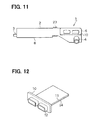
- FIG. 11 is a front view of a modified intake module
- FIG. 12 is a perspective view of an ECU.
- an intake module 1 includes a casing 2 which is made of a resin, such as polypropylene.
- the casing 2 has an air intake passage in the middle hollow part, an air inlet 3 , and an air outlet 4 .
- An air cleaner 5 is housed near the air inlet 3 .
- the air flows into the air module 1 from the air inlet 3 , passes through the air cleaner 5 , and flows out of the intake module 1 via the air outlet 4 .
- the air outputted from the intake module 1 is inputted to the engine E via an intake hose (not shown).
- the casing 2 further includes an ECU housing portion 6 for housing an ECU 10 .
- the ECU hosing portion 6 has a slot 7 , an opening of which is located on the side adjacent to the air outlet 4 .
- a circuit board 11 of the ECU 10 is inserted into the slot 7 through the opening as shown in FIG. 2 .
- the ECU 10 also has connectors 12 .
- the ECU housing portion 6 has a plurality of reinforcement ribs 9 extended from the outer periphery.
- the reinforcement ribs 9 are formed together with the casing 2 when the casing 2 is formed.
- the reinforcement ribs 9 are evenly spaced in the longitudinal direction of the intake module 1 .
- the thickness T 2 of the reinforcement ribs 9 is thinner than the thickness T 1 of the casing 2 as shown in FIG. 4 .
- a resin treated piece, such as the casing 2 has even thickness for convenience in molding.
- An air cleaner housing portion 8 is fixed on the engine E with three or four mounting screws (not shown).
- the ECU housing portion 6 is not supported from the underneath.
- a serviceperson may put his or her hand on the ECU hosing portion 6 as shown in FIG. 5 . In that case, a downward force is applied to the intake module 1 , as indicated with an arrow in FIG. 5 .
- the strength of the ECU housing portion 6 is improved with the reinforcement ribs 9 . Therefore, damages to the ECU 10 can be reduced.
- the reinforcement ribs 9 are provided parallel to the long side of the intake module, covering the ECU housing portion 6 . Therefore, effective reinforcement can be provided.
- the thickness of the reinforcement ribs 9 is smaller than the thickness of the other part of the casing 2 . Therefore, the heat radiation via the reinforcement ribs 9 is improved, and the operating condition of the ECU 10 is improved.
- the reinforcement ribs 9 are positioned at an angle with respect to the long side of the intake module 1 as shown in FIG. 6 .
- the reinforcement ribs 9 may be unevenly spaced.
- the reinforcement ribs 9 can be in the form of lattice, or in patterns, such as a logo and a symbol.
- the reinforcement ribs 9 can be formed ornamentally. However, it is preferable that the reinforcement ribs 9 are arranged parallel to the long side of the intake module 1 to tolerate with the force applied to the intake module 1 .
- the reinforcement ribs 9 may be formed on an inner periphery of the ECU hosing portion 6 as shown in FIG. 7 . Shapes and patterns of the ribs 9 can be arranged as same as in the case of the outer periphery.
- the ECU housing portion 6 may have a large thickness in areas that cover top and bottom surfaces of a circuit board 11 of the ECU 10 . This improves rigidity of the ECU housing portion 6 .
- a separate reinforcement member may be attached to the ECU housing portion 6 , for example, a substantially L-shaped reinforcement plate 21 is attached, as shown in FIG. 9.
- a degree of strength of the reinforcement can be varied as necessary by changing the thickness of the reinforcement plate 21 .
- the reinforcement plate 21 can be a plane plate or a combination of different parts.
- a plurality of ditches 22 can be formed on the surface of the reinforcement plate 21 .
- the reinforcement plate 21 may be made of different material from the casing 2 .
- the reinforcement plate 21 is made of a metal material, which has higher rigidity than the resin, which is the material the casing 2 is made of. If heat radiation characteristic is considered, the reinforcement plate 21 may be made of copper or aluminum.
- a flexible portion may be provided between the air cleaner housing portion 8 and the ECU housing portion 6 . More specifically, an accordion-shaped portion 23 , which corresponds to the flexible portion, is provided between the air cleaner housing portion 8 and the ECU housing portion 6 , as shown in FIG. 11 . The accordion-shaped portion 23 absorbs a force applied to the ECU housing portion 6 .
- the circuit board 11 of the ECU 10 may be sandwiched by reinforcement plates 24 . This improves the rigidity of the circuit board 11 and damages to the ECU 10 can be reduced.
Abstract
An intake module for a vehicular engine has a casing that is constructed of an air cleaner housing portion and an electronic control unit (ECU) housing portion. The air cleaner housing portion that houses an air cleaner is mounted on the engine. The ECU housing portion that houses an ECU is connected with the air cleaner housing portion. A plurality of reinforcement ribs is formed on an outer periphery of the ECU housing portion.
Description
This application is based on and incorporates herein by reference Japanese Patent Application No. 2002-22850 filed on Jan. 31, 2002.
The present invention relates to an intake module, in which an electronic control unit (ECU) is integrally housed, for a vehicular engine.
An intake module, in which an electronic control unit (ECU) is housed, used for a vehicular engine has been introduced. By integrally housing an ECU in an intake module, assembling steps can be reduced. The intake module is constructed of an air cleaner housing portion, an intake air passage portion, and an ECU housing portion. The air cleaner housing portion is fixed on an engine, and the ECU housing portion is positioned away from the engine to reduce the influence of heat.
When a vehicle is under service, a force may be applied to the ECU housing portion, for instance, a serviceperson put his or her hand on the ECU housing portion. As a result, the ECU assembly may be damaged. This creates a problem in engine control.
The present invention therefore has an objective to provide an intake module that includes a reinforcement member for an integrally housed ECU to tolerate with an external force.
An intake module of the present invention has a casing that is constructed of an air cleaner housing portion and an ECU housing portion. The air cleaner housing portion and the ECU housing portion are integrated, and the air cleaner housing portion is fixed on an engine. The ECU housing portion is not supported from the underneath but has a reinforcement member to improve the rigidity of the ECU housing portion. Therefore, the damage to the ECU in the ECU housing portion is reduced.
The above and other objectives, features and advantages of the present invention will become more apparent from the following detailed description made with reference to the accompanying drawings. In the drawings:
The preferred embodiments of the present invention will be explained with reference to the accompanying drawings.
Referring to FIG. 1 , an intake module 1 includes a casing 2 which is made of a resin, such as polypropylene. The casing 2 has an air intake passage in the middle hollow part, an air inlet 3, and an air outlet 4. An air cleaner 5 is housed near the air inlet 3. The air flows into the air module 1 from the air inlet 3, passes through the air cleaner 5, and flows out of the intake module 1 via the air outlet 4. The air outputted from the intake module 1 is inputted to the engine E via an intake hose (not shown).
The casing 2 further includes an ECU housing portion 6 for housing an ECU 10. The ECU hosing portion 6 has a slot 7, an opening of which is located on the side adjacent to the air outlet 4. A circuit board 11 of the ECU 10 is inserted into the slot 7 through the opening as shown in FIG. 2. The ECU 10 also has connectors 12.
Referring to FIGS. 1 through 3 , the ECU housing portion 6 has a plurality of reinforcement ribs 9 extended from the outer periphery. The reinforcement ribs 9 are formed together with the casing 2 when the casing 2 is formed. The reinforcement ribs 9 are evenly spaced in the longitudinal direction of the intake module 1. The thickness T2 of the reinforcement ribs 9 is thinner than the thickness T1 of the casing 2 as shown in FIG. 4. In general, a resin treated piece, such as the casing 2, has even thickness for convenience in molding.
An air cleaner housing portion 8 is fixed on the engine E with three or four mounting screws (not shown). The ECU housing portion 6 is not supported from the underneath. During service of a vehicle, a serviceperson may put his or her hand on the ECU hosing portion 6 as shown in FIG. 5. In that case, a downward force is applied to the intake module 1, as indicated with an arrow in FIG. 5. However, the strength of the ECU housing portion 6 is improved with the reinforcement ribs 9. Therefore, damages to the ECU 10 can be reduced.
Moreover, the reinforcement ribs 9 are provided parallel to the long side of the intake module, covering the ECU housing portion 6. Therefore, effective reinforcement can be provided. The thickness of the reinforcement ribs 9 is smaller than the thickness of the other part of the casing 2. Therefore, the heat radiation via the reinforcement ribs 9 is improved, and the operating condition of the ECU 10 is improved.
The present invention should not be limited to the embodiment previously discussed and shown in the figures, but may be implemented in various ways without departing from the spirit of the invention.
For example, the reinforcement ribs 9 are positioned at an angle with respect to the long side of the intake module 1 as shown in FIG. 6. The reinforcement ribs 9 may be unevenly spaced. Alternatively, the reinforcement ribs 9 can be in the form of lattice, or in patterns, such as a logo and a symbol. The reinforcement ribs 9 can be formed ornamentally. However, it is preferable that the reinforcement ribs 9 are arranged parallel to the long side of the intake module 1 to tolerate with the force applied to the intake module 1.
The reinforcement ribs 9 may be formed on an inner periphery of the ECU hosing portion 6 as shown in FIG. 7. Shapes and patterns of the ribs 9 can be arranged as same as in the case of the outer periphery. The ECU housing portion 6 may have a large thickness in areas that cover top and bottom surfaces of a circuit board 11 of the ECU 10. This improves rigidity of the ECU housing portion 6.
A separate reinforcement member may be attached to the ECU housing portion 6, for example, a substantially L-shaped reinforcement plate 21 is attached, as shown in FIG. 9. A degree of strength of the reinforcement can be varied as necessary by changing the thickness of the reinforcement plate 21. The reinforcement plate 21 can be a plane plate or a combination of different parts. A plurality of ditches 22 can be formed on the surface of the reinforcement plate 21. When the ECU housing portion 6 and the reinforcement plate 21 are made of the same resin material, they are bonded by the ultrasonic bonding. Alternatively, they are bonded with screws.
The reinforcement plate 21 may be made of different material from the casing 2. For example, the reinforcement plate 21 is made of a metal material, which has higher rigidity than the resin, which is the material the casing 2 is made of. If heat radiation characteristic is considered, the reinforcement plate 21 may be made of copper or aluminum.
A flexible portion may be provided between the air cleaner housing portion 8 and the ECU housing portion 6. More specifically, an accordion-shaped portion 23, which corresponds to the flexible portion, is provided between the air cleaner housing portion 8 and the ECU housing portion 6, as shown in FIG. 11. The accordion-shaped portion 23 absorbs a force applied to the ECU housing portion 6.
The circuit board 11 of the ECU 10 may be sandwiched by reinforcement plates 24. This improves the rigidity of the circuit board 11 and damages to the ECU 10 can be reduced.
Claims (33)
1. An intake module for a vehicular engine in which an electronic control unit is integrally housed, comprising:
a casing that is constructed of an air cleaner housing portion and an electronic control unit housing portion connected with the air cleaner housing portion; and
a reinforcement member that is formed in the electronic control unit housing portion, wherein
the casing has a first surface and a second surface;
the first surface of the casing includes the reinforcement member;
the second surface of the casing is located opposite to the first surface and fixed to another part at least in the air cleaner housing portion;
the air cleaner housing portion is provided for housing an air cleaner for a vehicular engine;
the electronic control unit includes a circuit board that has a flat portion;
the electronic control unit housing portion is provided for housing the electronic control unit in such a manner that a surface of the flat portion of the circuit board is parallel to the first surface of the casing; and
the casing is arranged such that the flat portion of the circuit board is horizontal to the vehicular engine.
2. The intake module according to claim 1 , wherein the reinforcement member is formed on an outer periphery of the electronic control unit housing portion.
3. The intake module according to claim 1 , wherein the reinforcement member is formed on an inner periphery of the electronic control unit housing portion.
4. The intake module according to claim 1 , wherein the reinforcement member is arranged parallel to a long side of the intake module.
5. The intake module according to claim 1 , wherein: the reinforcement member is in a form of reinforcement ribs; the reinforcement ribs are extended from the electronic control unit housing portion; and the reinforcement ribs have a thickness smaller than the casing.
6. The intake module according to claim 1 , wherein: the reinforcement member is provided separately from the electronic control unit housing portion; and the reinforcement member is mounted so that it covers the electronic control unit housing portion.
7. The intake module according to claim 6 , wherein the reinforcement member is made of a material with higher rigidity than a material of the electronic control unit housing portion.
8. The intake module according to claim 7 , wherein the material of the reinforcement member has good heat radiating characteristic.
9. An intake module for a vehicular engine in which an electronic control unit is integrally housed, comprising a casing that is constructed of an air cleaner housing portion and an electronic control unit housing portion connected with the air cleaner housing portion, wherein:
the casing has a first surface and a second surface;
the first surface has a large thickness in the electronic control unit housing portion;
the second surface is located opposite to the first surface and fixed to another part at least in the air cleaner housing portion;
the electronic control unit includes a circuit board that has a flat portion;
the electronic control unit housing portion houses the electronic control unit in such a manner that a surface of the flat portion of the circuit board is parallel to the first surface; and
the casing is arranged such that the flat portion of the circuit board is horizontal to the vehicular engine.
10. An intake module for a vehicular engine in which an electronic control unit is integrally housed, comprising a casing that is constructed of an air cleaner housing portion that houses an air cleaner for the vehicular engine, an electronic control unit housing portion that houses an electronic control unit, and a flexible portion, wherein:
the casing has a first surface and a second surface;
the first surface and the second surface are opposed to each other;
the second surface of the casing is fixed to another part at least in the air cleaner housing portion;
the electronic control unit includes a circuit board that has a flat portion;
the electronic control unit housing portion houses the electronic control unit in such a manner that a surface of the flat portion of the circuit board is parallel to the first surface of the casing;
the electronic control housing portion is connected with the air cleaner housing portion via the flexible portion; and
the casing is arranged such that the flat portion of the circuit board is horizontal to the vehicular engine.
11. An intake module for a vehicular engine in which an electronic control unit is integrally housed, comprising a casing that is constructed of an air cleaner housing portion and an electronic control unit housing portion connected with the air cleaner housing portion, wherein:
the casing has a first surface and a second surface;
the second surface is located opposite to the first surface and fixed to another part;
the air cleaner housing portion is provided for housing an air cleaner for the vehicular engine;
the electronic control unit housing portion is provided for housing the electronic control unit;
the electronic control unit includes a circuit board that has a flat portion;
the circuit board is reinforced with a reinforcement member that is attached to the flat portion of the circuit board;
the electronic control unit is housed in the electronic control unit housing portion in such a manner that a surface of the flat portion of the circuit board is parallel to the first surface of the casing; and
the casing is arranged such that the flat portion of the circuit board is horizontal to the vehicular engine.
12. An electronic control unit for a vehicular engine comprising:
a circuit board having a flat shape on which electronic parts are mounted;
a housing portion in which said circuit board is inserted, a major surface of the house portion covering the flat portion of the circuit board and being arranged in a horizontal direction with respect to the vehicular engine; and
a reinforcement member formed in said major surface of the housing portion,
wherein said major surface of the housing portion is provided as a hand placement portion for a person, and the reinforcement member in the major surface of the housing portion serves as a protection for the circuit board from downward force applied when a hand is placed on the major surface of the housing portions, and
wherein the casing is arranged such that the flat portion of the circuit board is horizontal to the vehicular engine.
13. The electronic control unit according to claim 12 , wherein said housing portion is a part integrated into a module unit for the vehicular engine.
14. The electronic control unit according to claim 13 , wherein said module unit is provided on the vehicular engine.
15. The electronic control unit according to claim 14 , wherein said housing portion is off set from the vehicular engine.
16. The electronic control unit according to claim 14 , wherein said module unit is an air intake module for the vehicular engine.
17. The intake module according to claim 1 , wherein the electronic control unit housing portion is arranged away from where the air cleaner housing portion is fixed.
18. The intake module according to claim 9 , wherein the electronic control unit housing portion is arranged away from where the air cleaner housing portion is fixed.
19. The intake module according to claim 10 , wherein the electronic control unit housing portion is arranged away from where the air cleaner housing portion is fixed.
20. The intake module according to claim 11 , wherein the electronic control unit housing portion is arranged away from where the air cleaner housing portion is fixed.
21. The intake module according to claim 1 , wherein said another part is the vehicular engine.
22. The intake module according to claim 9 , wherein said another part is the vehicular engine.
23. The intake module according to claim 10 , wherein said another part is the vehicular engine.
24. The intake module according to claim 11 , wherein said another part is the vehicular engine.
25. The intake module according to claim 21 , wherein the casing is formed in a flat shape and is arranged on the vehicular engine.
26. The intake module according to claim 22 , wherein the casing is formed in a flat shape and is arranged on the vehicular engine.
27. The intake module according to claim 23 , wherein the casing is formed in a flat shape and is arranged on the vehicular engine.
28. The intake module according to claim 24 , wherein the casing is formed in a flat shape and is arranged on the vehicular engine.
29. The intake module according to claim 1 , wherein the reinforcement member has a good heat radiating characteristic.
30. The intake module according to claim 1 , wherein the electronic control unit housing portion has a slot for housing the circuit board, and the slot is closed by a part of the electronic control unit including a connector for electrical connection with an external device, the connector protruding from the casing.
31. The intake module according to claim 9 , wherein the electronic control unit housing portion has a slot for housing the circuit board, and the slot is closed by a part of the electronic control unit including a connector for electrical connection with an external device, the connector protruding from the casing.
32. The intake module according to claim 10 , wherein the electronic control unit housing portion has a slot for housing the circuit board, and the slot is closed by a part of the electronic control unit including a connector for electrical connection with an external device, the connector protruding from the casing.
33. The intake module according to claim 11 , wherein the electronic control unit housing portion has a slot for housing the circuit board, and the slot is closed by a part of the electronic control unit including a connector for electrical connection with an external device, the connector protruding from the casing.
Applications Claiming Priority (2)
| Application Number | Priority Date | Filing Date | Title |
|---|---|---|---|
| JP2002-22850 | 2002-01-31 | ||
| JP2002022850A JP3722365B2 (en) | 2002-01-31 | 2002-01-31 | Electronic control unit integrated intake module |
Publications (2)
| Publication Number | Publication Date |
|---|---|
| US20030142454A1 US20030142454A1 (en) | 2003-07-31 |
| US6910456B2 true US6910456B2 (en) | 2005-06-28 |
Family
ID=27606370
Family Applications (1)
| Application Number | Title | Priority Date | Filing Date |
|---|---|---|---|
| US10/341,248 Expired - Lifetime US6910456B2 (en) | 2002-01-31 | 2003-01-14 | Intake module having integrally housed ECU |
Country Status (3)
| Country | Link |
|---|---|
| US (1) | US6910456B2 (en) |
| JP (1) | JP3722365B2 (en) |
| DE (1) | DE10303763A1 (en) |
Families Citing this family (2)
| Publication number | Priority date | Publication date | Assignee | Title |
|---|---|---|---|---|
| DE102017000699A1 (en) | 2017-01-26 | 2018-07-26 | Man Truck & Bus Ag | Device for attaching a control device to an internal combustion engine |
| JP7273697B2 (en) * | 2019-11-19 | 2023-05-15 | 株式会社やまびこ | power work machine |
Citations (6)
| Publication number | Priority date | Publication date | Assignee | Title |
|---|---|---|---|---|
| US6067953A (en) * | 1997-08-27 | 2000-05-30 | Siemens Canada Limited | Integrated intake manifold and air cleaner system |
| US6167862B1 (en) * | 1999-05-12 | 2001-01-02 | Siemens Canada Limited | Air cleaner system |
| US6318329B1 (en) | 1998-07-23 | 2001-11-20 | Sanshin Kogyo Kabushiki Kaisha | Vibration damping mount for engine control components |
| US6341063B2 (en) * | 2000-02-02 | 2002-01-22 | Denso Corporation | Installation structure of printed-circuit board for electronic control unit |
| US6513479B2 (en) * | 2000-05-10 | 2003-02-04 | Autonetworks Technologies, Ltd. | Harness structure of engine relative parts |
| US6644249B2 (en) * | 2001-02-07 | 2003-11-11 | Denso Corporation | Cooling mechanism for engine electronic control module |
-
2002
- 2002-01-31 JP JP2002022850A patent/JP3722365B2/en not_active Expired - Fee Related
-
2003
- 2003-01-14 US US10/341,248 patent/US6910456B2/en not_active Expired - Lifetime
- 2003-01-30 DE DE10303763A patent/DE10303763A1/en not_active Ceased
Patent Citations (6)
| Publication number | Priority date | Publication date | Assignee | Title |
|---|---|---|---|---|
| US6067953A (en) * | 1997-08-27 | 2000-05-30 | Siemens Canada Limited | Integrated intake manifold and air cleaner system |
| US6318329B1 (en) | 1998-07-23 | 2001-11-20 | Sanshin Kogyo Kabushiki Kaisha | Vibration damping mount for engine control components |
| US6167862B1 (en) * | 1999-05-12 | 2001-01-02 | Siemens Canada Limited | Air cleaner system |
| US6341063B2 (en) * | 2000-02-02 | 2002-01-22 | Denso Corporation | Installation structure of printed-circuit board for electronic control unit |
| US6513479B2 (en) * | 2000-05-10 | 2003-02-04 | Autonetworks Technologies, Ltd. | Harness structure of engine relative parts |
| US6644249B2 (en) * | 2001-02-07 | 2003-11-11 | Denso Corporation | Cooling mechanism for engine electronic control module |
Also Published As
| Publication number | Publication date |
|---|---|
| DE10303763A1 (en) | 2003-10-16 |
| JP2003222058A (en) | 2003-08-08 |
| JP3722365B2 (en) | 2005-11-30 |
| US20030142454A1 (en) | 2003-07-31 |
Similar Documents
| Publication | Publication Date | Title |
|---|---|---|
| US7113400B2 (en) | Housing structure of electronic control unit and mounting structure of the same | |
| JP4006189B2 (en) | Control unit structure for vehicle | |
| KR970011610A (en) | The outdoor unit of the air conditioner | |
| JP4366863B2 (en) | Electronic control unit | |
| US7661923B2 (en) | Casing, equipment unit and fan units provided with the casing, and electronic equipment provided with the fan units | |
| US7535712B2 (en) | Electronic apparatus | |
| JPH11112172A (en) | Electric device provided with printed circuit board and junction method for the electric device | |
| WO2005028259A1 (en) | Mounting structure of on-vehicle circuit unit and on-vehicle circuit unit | |
| US6273181B1 (en) | Cooling device for electronic parts of vehicle | |
| US20110277970A1 (en) | Heat exchanger device and heating element holder using same | |
| JP3794879B2 (en) | Fuel supply device | |
| US6788534B2 (en) | Intake module having integrated ECU | |
| JP6584547B2 (en) | Electronic control unit | |
| US7180739B2 (en) | Electronic equipment | |
| US6910456B2 (en) | Intake module having integrally housed ECU | |
| JPWO2018109932A1 (en) | Air conditioner outdoor unit | |
| WO2004085209A1 (en) | A vehicle electronic control unit | |
| JP3955717B2 (en) | Engine integrated control device and circuit body used therefor | |
| JP4524667B2 (en) | Electrical junction box | |
| JP3748328B2 (en) | Sensor | |
| US9155224B2 (en) | Thermally controlled assembly | |
| JP5203416B2 (en) | Mounting structure for in-vehicle circuit unit and electrical junction box | |
| US5661636A (en) | IC card with on-board hard disk and circuit board with on-board hard disk including a cover with a bulging portion accommodating the hard disk | |
| JP2002520206A (en) | Housing for electronic units, especially for airbag controls | |
| JP2005093905A (en) | Electronic substrate unit |
Legal Events
| Date | Code | Title | Description |
|---|---|---|---|
| AS | Assignment |
Owner name: DENSO, CORPORATION, JAPAN Free format text: ASSIGNMENT OF ASSIGNORS INTEREST;ASSIGNORS:UMEMOTO, SATORU;NIWA, MASAYUKI;REEL/FRAME:013662/0158;SIGNING DATES FROM 20021224 TO 20030108 |
|
| STCF | Information on status: patent grant |
Free format text: PATENTED CASE |
|
| FPAY | Fee payment |
Year of fee payment: 4 |
|
| FPAY | Fee payment |
Year of fee payment: 8 |
|
| FEPP | Fee payment procedure |
Free format text: PAYER NUMBER DE-ASSIGNED (ORIGINAL EVENT CODE: RMPN); ENTITY STATUS OF PATENT OWNER: LARGE ENTITY |
|
| FPAY | Fee payment |
Year of fee payment: 12 |