US6903545B2 - Rotation detecting device for detecting rotation of a vehicle wheel - Google Patents
Rotation detecting device for detecting rotation of a vehicle wheel Download PDFInfo
- Publication number
- US6903545B2 US6903545B2 US10/380,001 US38000103A US6903545B2 US 6903545 B2 US6903545 B2 US 6903545B2 US 38000103 A US38000103 A US 38000103A US 6903545 B2 US6903545 B2 US 6903545B2
- Authority
- US
- United States
- Prior art keywords
- rotation
- detected
- detecting
- detecting device
- rotation transmitting
- Prior art date
- Legal status (The legal status is an assumption and is not a legal conclusion. Google has not performed a legal analysis and makes no representation as to the accuracy of the status listed.)
- Expired - Lifetime
Links
- 238000003780 insertion Methods 0.000 claims abstract description 27
- 230000037431 insertion Effects 0.000 claims abstract description 27
- 230000005389 magnetism Effects 0.000 claims abstract description 24
- 230000002093 peripheral effect Effects 0.000 claims description 21
- 239000000463 material Substances 0.000 claims description 11
- 230000001050 lubricating effect Effects 0.000 claims description 6
- 238000000465 moulding Methods 0.000 claims description 6
- 238000003860 storage Methods 0.000 description 9
- 238000005304 joining Methods 0.000 description 7
- 238000004519 manufacturing process Methods 0.000 description 7
- 238000001514 detection method Methods 0.000 description 6
- 230000005540 biological transmission Effects 0.000 description 5
- 239000000470 constituent Substances 0.000 description 5
- 229920005989 resin Polymers 0.000 description 5
- 239000011347 resin Substances 0.000 description 5
- 238000010276 construction Methods 0.000 description 4
- 239000004033 plastic Substances 0.000 description 4
- 239000004677 Nylon Substances 0.000 description 3
- 238000005299 abrasion Methods 0.000 description 3
- 239000000314 lubricant Substances 0.000 description 3
- 238000005461 lubrication Methods 0.000 description 3
- 239000007769 metal material Substances 0.000 description 3
- 229920001778 nylon Polymers 0.000 description 3
- 239000004593 Epoxy Substances 0.000 description 2
- 229930182556 Polyacetal Natural products 0.000 description 2
- 230000002708 enhancing effect Effects 0.000 description 2
- 238000000034 method Methods 0.000 description 2
- 229920006324 polyoxymethylene Polymers 0.000 description 2
- 239000003566 sealing material Substances 0.000 description 2
- 238000005476 soldering Methods 0.000 description 2
- 235000014676 Phragmites communis Nutrition 0.000 description 1
- 239000004642 Polyimide Substances 0.000 description 1
- 229910000639 Spring steel Inorganic materials 0.000 description 1
- 229910000831 Steel Inorganic materials 0.000 description 1
- 239000003990 capacitor Substances 0.000 description 1
- 238000006073 displacement reaction Methods 0.000 description 1
- 230000005611 electricity Effects 0.000 description 1
- 239000003822 epoxy resin Substances 0.000 description 1
- 239000011521 glass Substances 0.000 description 1
- 239000004519 grease Substances 0.000 description 1
- 239000011810 insulating material Substances 0.000 description 1
- 125000005245 nitryl group Chemical group [N+](=O)([O-])* 0.000 description 1
- -1 polybutylene terephthalate Polymers 0.000 description 1
- 229920001707 polybutylene terephthalate Polymers 0.000 description 1
- 229920000647 polyepoxide Polymers 0.000 description 1
- 229920001721 polyimide Polymers 0.000 description 1
- 229920001296 polysiloxane Polymers 0.000 description 1
- 230000002265 prevention Effects 0.000 description 1
- 239000004065 semiconductor Substances 0.000 description 1
- 238000000926 separation method Methods 0.000 description 1
- 239000010959 steel Substances 0.000 description 1
- 239000000758 substrate Substances 0.000 description 1
Images


Classifications
-
- G—PHYSICS
- G01—MEASURING; TESTING
- G01P—MEASURING LINEAR OR ANGULAR SPEED, ACCELERATION, DECELERATION, OR SHOCK; INDICATING PRESENCE, ABSENCE, OR DIRECTION, OF MOVEMENT
- G01P3/00—Measuring linear or angular speed; Measuring differences of linear or angular speeds
- G01P3/42—Devices characterised by the use of electric or magnetic means
- G01P3/44—Devices characterised by the use of electric or magnetic means for measuring angular speed
- G01P3/48—Devices characterised by the use of electric or magnetic means for measuring angular speed by measuring frequency of generated current or voltage
- G01P3/481—Devices characterised by the use of electric or magnetic means for measuring angular speed by measuring frequency of generated current or voltage of pulse signals
- G01P3/487—Devices characterised by the use of electric or magnetic means for measuring angular speed by measuring frequency of generated current or voltage of pulse signals delivered by rotating magnets
-
- G—PHYSICS
- G01—MEASURING; TESTING
- G01D—MEASURING NOT SPECIALLY ADAPTED FOR A SPECIFIC VARIABLE; ARRANGEMENTS FOR MEASURING TWO OR MORE VARIABLES NOT COVERED IN A SINGLE OTHER SUBCLASS; TARIFF METERING APPARATUS; MEASURING OR TESTING NOT OTHERWISE PROVIDED FOR
- G01D5/00—Mechanical means for transferring the output of a sensing member; Means for converting the output of a sensing member to another variable where the form or nature of the sensing member does not constrain the means for converting; Transducers not specially adapted for a specific variable
- G01D5/12—Mechanical means for transferring the output of a sensing member; Means for converting the output of a sensing member to another variable where the form or nature of the sensing member does not constrain the means for converting; Transducers not specially adapted for a specific variable using electric or magnetic means
- G01D5/14—Mechanical means for transferring the output of a sensing member; Means for converting the output of a sensing member to another variable where the form or nature of the sensing member does not constrain the means for converting; Transducers not specially adapted for a specific variable using electric or magnetic means influencing the magnitude of a current or voltage
- G01D5/142—Mechanical means for transferring the output of a sensing member; Means for converting the output of a sensing member to another variable where the form or nature of the sensing member does not constrain the means for converting; Transducers not specially adapted for a specific variable using electric or magnetic means influencing the magnitude of a current or voltage using Hall-effect devices
- G01D5/145—Mechanical means for transferring the output of a sensing member; Means for converting the output of a sensing member to another variable where the form or nature of the sensing member does not constrain the means for converting; Transducers not specially adapted for a specific variable using electric or magnetic means influencing the magnitude of a current or voltage using Hall-effect devices influenced by the relative movement between the Hall device and magnetic fields
-
- G—PHYSICS
- G01—MEASURING; TESTING
- G01D—MEASURING NOT SPECIALLY ADAPTED FOR A SPECIFIC VARIABLE; ARRANGEMENTS FOR MEASURING TWO OR MORE VARIABLES NOT COVERED IN A SINGLE OTHER SUBCLASS; TARIFF METERING APPARATUS; MEASURING OR TESTING NOT OTHERWISE PROVIDED FOR
- G01D5/00—Mechanical means for transferring the output of a sensing member; Means for converting the output of a sensing member to another variable where the form or nature of the sensing member does not constrain the means for converting; Transducers not specially adapted for a specific variable
- G01D5/12—Mechanical means for transferring the output of a sensing member; Means for converting the output of a sensing member to another variable where the form or nature of the sensing member does not constrain the means for converting; Transducers not specially adapted for a specific variable using electric or magnetic means
- G01D5/25—Selecting one or more conductors or channels from a plurality of conductors or channels, e.g. by closing contacts
- G01D5/251—Selecting one or more conductors or channels from a plurality of conductors or channels, e.g. by closing contacts one conductor or channel
- G01D5/2515—Selecting one or more conductors or channels from a plurality of conductors or channels, e.g. by closing contacts one conductor or channel with magnetically controlled switches, e.g. by movement of a magnet
Definitions
- the present invention relates to an electric type rotation detecting device for detecting rotation of a wheel of a two-wheeler, for example, autobicycles, bicycles, or the like, and transmitting the detected signal to a speedometer, or the like.
- JP-A-2-264817 discloses a conventional rotation detecting device adopting a configuration, in which a magnetism detecting element composed of a hall IC, or the like, mounted on a circuit board, and a magnet are arranged on a substantially cylindrical-shaped resin casing, which comprises a detection surface for detection of a body being detected, in a manner to extend along the detection surface, and the circuit board, magnetism detecting element, and the magnet are sealed by a sealing material such as epoxy.
- the rotation detecting device is used as a rotation detecting device for a two-wheeler (for example, autobicycles), it is general that the rotation detecting device is mounted on a transmission casing, sprocket cover, or the like, of the vehicle and transmission gears, sprockets, or the like, rotating therein serve as a body being detected for detection.
- This rotation detecting device is adapted to be mounted on a front wheel (wheel) in a two-wheeler such as autobicycles, and constructed to comprise a housing provided with an insertion portion, through which an axle shaft mounting thereon the front wheel is inserted, the insertion portion having a plurality of magnetic poles for rotation with the front wheel, the rotation detecting device mounting thereon a body being detected, which body is made of a magnetic medium such as plastic magnet, and magnetism detecting means made of a hall IC, or the like, for detecting a change in the magnetic poles, caused by rotation of the body being detected.
- a cylindrical portion having the magnetic poles and rotation transmitting pieces for transmitting rotation of the front wheel to the cylindrical portion are formed integral by means of a plastic magnet, or the like.
- the rotation transmitting pieces are formed to extend outside of the cylindrical portion on an opening side of the housing so as to correspond to a recessed mount provided on a hub of the front wheel, the rotation transmitting pieces being provided in a plurality of locations on a peripheral edge of the cylindrical portion.
- the rotation detecting device constructed in the above manner is arranged in a state, in which it is interposed between the front wheel and a front fork. More specifically, the rotation detecting device is arranged in a state, in which it is interposed between the front wheel and the front fork, by inserting the axle shaft, on which the front wheel is mounted, into the insertion portion, fitting the rotation transmitting pieces into the mount provided on the hub of the front wheel, and using nut members to fix the axle shaft, which projects outside the housing from the insertion portion, through the front fork.
- the present invention takes notice of the problem and provides a rotation detecting device capable of being mounted to a hub of a wheel, without breakage of constituent parts of the rotation detecting device, even in the case where the rotation detecting device is arranged on the wheel in an inappropriate state.
- the invention provides a rotation detecting device, in which a body being detected, for rotation with a wheel is mounted on that insertion portion of a housing, through which an axle shaft is inserted, and rotation of the body being detected is detected by magnetism detecting means, characterized in that the body being detected comprises a detecting portion, rotation of which is detected by the magnetism detecting means, and a rotation transmitting portion for transmitting rotation of the wheel to the detecting portion, and the rotation transmitting portion is made of an elastic member.
- the rotation transmitting portion is made of an elastic member whereby the rotation detecting device can be mounted to the hub of the wheel without breakage of constituent parts of the rotation detecting device, even in the case where the rotation detecting device is arranged on the wheel in an inappropriate state, and there is caused no need of exchanging the body being detected (exchange of constituent parts) and exchanging the rotation detecting device itself, thereby enabling enhancing the yield of rotation detecting devices in the manufacturing process.
- the invention has a feature in that the detecting portion comprises a first fixing portion or portions provided substantially perpendicular to the axle shaft, and the rotation transmitting portion comprises a second fixing portion or portions joined to the first fixing portion.
- the invention has a feature in that one of the first and second fixing portions comprises a projection or projections provided substantially perpendicular to the axle shaft, and the other of the first and second fixing portions comprises a recess or recesses formed to correspond to the projection or projections.
- the invention has a feature in that an abutting portion to abut against the insertion portion is provided on the rotation transmitting portion, and a gap is formed between the insertion portion and the detecting portion.
- an inner peripheral surface of the detecting portion can be made not to abut against the insertion portion, so that it is possible to prevent abrasion of the detecting portion.
- the invention has a feature in that the detecting portion and the rotation transmitting portion are provided separately on the body being detected.
- the detecting portion and the rotation transmitting portion are provided separately on the body being detected, whereby it suffices to exchange only the rotation transmitting portion even if an inappropriate mount state were repeated several times and the rotation transmitting portion were broken, and so it is possible to reduce the cost for disposal of parts, caused by breakage.
- the invention has a feature in that the detecting portion and the rotation transmitting portion are joined together by means of concavo-convex fitting.
- the detecting portion and the rotation transmitting portion are joined together by means of concavo-convex fitting whereby joining by means of concavo-convex fitting affords transmission of rotation free of shaking in rotation of the detecting portion when rotation of the front wheel is transmitted to the detecting portion through the rotation transmitting portion, so that rotation can be favorably detected by the magnetism detecting means.
- the invention has a feature in that the body being detected is formed integrally by insert-molding of the detecting portion and the rotation transmitting portion.
- the detecting portion and the rotation transmitting portion are insert-molded whereby the detecting portion and the rotation transmitting portion can be formed integrally and so it is possible to inhibit the rotation transmitting portion from falling off, or being shifted in a mount position when mounted on a vehicle (two-wheeler) in the manufacturing process.
- the rotation transmitting portion is insert-molded to the detecting portion and the both portions are formed integrally whereby the assembling process of assembling the detecting portion and the rotation transmitting portion together is dispensed with, which provides a constitution of the body being detected, of excellent productivity.
- the invention has a feature in that the rotation transmitting portion is made of a lubricating material having the elasticity.
- the rotation transmitting portion is made of a lubricating material having the lubrication, lubrication can be ensured even when any lubricant is not applied on that portion, which abuts against the outer peripheral surface of the insertion portion.
- FIGS. 1 to 3 are views showing a first embodiment
- FIG. 1 being a view showing a rotation detecting device
- FIG. 2 being a view showing an assembled state of a portion being detected, of the rotation detecting device
- FIG. 3 being a view showing a body being detected, of the rotation detecting device.
- FIGS. 4 and 5 are views showing a second embodiment
- FIG. 4 being a view showing a rotation detecting device
- FIG. 5 being a view showing an elastic rotation transmitting portion of the rotation detecting device.
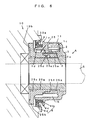
- FIG. 6 is a view showing a third embodiment and a rotation detecting device.
- a rotation detecting device A comprises a housing 1 made of a resin material, a circuit board 2 provided with a predetermined wiring pattern (not shown), a magnetism detecting element (magnetism detecting means) 3 , an elastic member 4 made of a rubber material, and a body 5 being detected.
- the housing 1 is made of a resin material such as polybutylene terephthalate or nylon, an axle shaft S is inserted substantially centrally of the housing 1 , and a cylindrical-shaped insertion portion 1 a is made of a metallic material and insert-molded.
- a first storage portion 1 b for permitting the body 5 being detected, described later, to be rotatably arranged on an outer periphery of the insertion portion 1 a
- a second storage portion 1 c for storing the circuit board 2 and the magnetism detecting element 3 installed on the circuit board 2 .
- a projecting piece 1 d projecting toward a front wheel 10 .
- the circuit board 2 comprises a substrate made of an insulating material such as glass epoxy and formed with a predetermined wiring pattern, and the magnetism detecting element 3 and electronic parts (not shown) composed of capacitors, or the like, are electrically fixed to the circuit board as by soldering. Also, the circuit board 2 is provided with wiring cords (not shown), which serve to supply electricity to the magnetism detecting element 3 and transmit an output signal from the magnetism detecting element 3 to an indicating instrument (not shown) (for example, a speedometer), the wiring cords being electrically connected to predetermined locations on the circuit board 2 by soldering.
- Such circuit board 2 is arranged and fixed by filling a sealing material 11 made of an epoxy resin, or the like, into the second storage portion 1 c after the board is arranged in the second storage portion 1 c.
- the magnetism detecting element 3 comprises reed switches, hall ICs, MR elements (semiconductor magnetoresistive element), or the like to detect a change in magnetic poles of the body 5 being detected.
- the elastic member 4 is made of a nitryl or silicone based rubber material, the elastic member 4 being thin and cylindrical-shaped. Formed on a side end surface of the elastic member 4 are an abutting portion 4 a having a substantially V-shaped cross section to abut against an mount portion 10 b of a hub 10 a of the front wheel 10 to gas tightly arrange the housing 1 of the rotation detecting device A on the hub 10 a , and an upright portion 4 b extended upward from the abutting portion 4 a . And insert-molded inside the upright portion 4 b is a holding member 4 c having a substantially L-shaped cross section and made of a metallic material.
- the upright portion 4 b of the elastic member 4 is formed such that its inner periphery is somewhat smaller in diameter than an outer diameter of the projecting piece 1 d of the housing 1 , the elastic member 4 is arranged and fixed by press fitting so that an upper end of the upright portion 4 b abuts against a flange portion 1 e of the housing 1 .
- the body 5 being detected is formed with a cylindrical portion (detecting portion) 5 a for insertion of the insertion portion 1 a of the housing 1 therethrough, the cylindrical portion 5 a being polarised to have, for example, eight poles, on a surface thereof.
- the cylindrical portion 5 a is made of, for example, plastic magnet, or the like.
- the body 5 being detected is provided with an elastic rotation transmitting portion 5 c having a plurality of pieces 5 b , which are composed of an elastic member made of a resin material such as nylon, polyacetal, or polyimide, and a metallic material such as spring steel or SPC rolled steel, and fitted into the mount portion 10 b formed on the hub 10 a of the front wheel 10 .
- the cylindrical portion 5 a and the elastic rotation transmitting portion 5 c of the body 5 being detected are joined together by concavo-convex fitting as shown in FIG. 2 . More specifically, a plurality of recesses 5 d are formed on that portion of an end of the cylindrical portion 5 a , which is opposed to the elastic rotation transmitting portion 5 c , and a plurality of projections 5 e are formed on the elastic rotation transmitting portion 5 c to correspond to the respective recesses 5 d , both elements 5 a , 5 c being joined together by concavo-convex fitting.
- the above constituents constitute the rotation detecting device A.
- rotation detecting device A When such rotation detecting device A is mounted on a vehicle (two-wheeler) in a manufacturing process, it is clamped between a front fork (not shown) and the front wheel 10 in a state (referred below to as inappropriate state), in which the pieces 5 b of the elastic rotation transmitting portion 5 c formed on the body 5 being detected are not arranged on the mount portion 10 b formed on the hub 10 a , then the rotation detecting device A is confirmed to be mounted in an inappropriate state while the pieces 5 b of the elastic rotation transmitting portion 5 c are deformed as indicated by dotted lines in FIG. 3 , and the rotation detecting device A is disengaged from the front wheel 10 whereby the pieces 5 b of the elastic rotation transmitting portion 5 c can be restored to an original state.
- the cylindrical portion 5 a and the elastic rotation transmitting portion 5 c are provided separately from each other. Accordingly, even if the inappropriate state were repeated several times and the pieces 5 b of the elastic rotation transmitting portion 5 c were broken, it suffices to exchange only the elastic rotation transmitting portion 5 c , thus enabling reducing the cost for disposal of parts, caused by breakage.
- cylindrical portion 5 a and the elastic rotation transmitting portion 5 c are joined together by concavo-convex fitting, and joining of the both elements 5 a , 5 c by means of concavo-convex fitting affords transmission of rotation free of shaking in rotation of the cylindrical portion 5 a when rotation of the front wheel 10 is transmitted to the cylindrical portion 5 a through the elastic rotation transmitting portion 5 c , so that rotation can be favorably detected by the magnetism detecting element 3 .
- FIGS. 4 and 5 show a second embodiment of the invention, the same reference numerals denoting parts, which are the same as or corresponding to those in the first embodiment, and an explanation therefor being omitted.
- a rotation detecting device A according to the second embodiment of the invention comprises a housing 1 , a circuit board 2 , a magnetism detecting element 3 , an elastic member 4 , and a body 15 being detected.
- the embodiment is different from the first embodiment in the construction of the body being detected.
- the body 15 being detected comprises a cylindrical portion 15 a being polarised, and an elastic rotation transmitting portion 15 c provided with a piece 15 b , which is provided corresponding to the mount portion 10 b formed on the hub 10 a of the front wheel 10 , the elastic rotation transmitting portion 15 c and the cylindrical portion 15 a being formed integrally by means of insert-molding.
- the cylindrical portion 15 a is polarised to have a plurality of poles on an outer peripheral surface thereof, and provided with first fixing portions 15 d , which comprise a plurality of projections formed in a manner to project substantially perpendicular to the axle shaft S, in an area where the cylindrical portion is joined to the elastic rotation transmitting portion 15 c disposed on a lower end thereof.
- the elastic rotation transmitting portion 15 c is provided with second fixing portions 15 e , which comprise a plurality of recesses corresponding to the first fixing portions 15 d , in an area where the elastic rotation transmitting portion is joined to the cylindrical portion 15 a disposed in the first storage portion 1 b of the housing 1 in a direction of depth from the piece 15 b .
- 5 ( a ) and 5 ( b ) show locations, in which the second fixing portions 15 e are formed, the second fixing portions being formed in four locations on an inner peripheral surface of the elastic rotation transmitting portion 15 c , and the first fixing portions 15 d being also formed on the cylindrical portion 15 a to be the same in number as the second fixing portions.
- the first and second fixing portions be one or more in number, and the number is not limited to that in the second embodiment.
- the body being detected is composed of the cylindrical portion 15 a being a detecting portion and the elastic rotation transmitting portion 15 c .
- the elastic rotation transmitting portion falls off when the rotation detecting device A is mounted on a vehicle (two-wheeler) in the manufacturing process.
- the cylindrical portion and the elastic rotation transmitting portion are separated from each other and the cylindrical portion idles.
- the elastic rotation transmitting portion 15 c and the cylindrical portion 15 a can be formed integrally by insert-molding the elastic rotation transmitting portion 15 c and the cylindrical portion 15 a , and so it is possible to inhibit the elastic rotation transmitting portion from falling off, or being shifted in a mount position when the rotation detecting device A is mounted on a vehicle (two-wheeler) in the manufacturing process. Also, with the rotation detecting device A, the elastic rotation transmitting portion 15 c is insert-molded on the cylindrical portion 15 a and so the both members are formed integrally, whereby the assembling process of assembling the cylindrical portion 15 a and the elastic rotation transmitting portion together is dispensed with, which provides a constitution of a body being detected, of excellent productivity.
- first fixing portions 15 d comprising projections provided substantially perpendicular to the axle shaft S are provided on the cylindrical portion 15 a
- second fixing portions 15 e comprising recesses corresponding to the first fixing portions 15 d are provided on the elastic rotation transmitting portion 15 c
- the first fixing portions 15 d and the second fixing portions 15 e are joined together to provide for concavo-convex fitting of joining portions of the cylindrical portion 15 a and the elastic rotation transmitting portion 15 c , whereby it is possible to prevent separation of the both portions from each other, and so it is possible to prevent the cylindrical portion 15 a from idling when the body 15 being detected is rotated.
- first fixing portions 15 d comprise projections provided on the cylindrical portion 15 a to be substantially perpendicular to the axle shaft S and the second fixing portions 15 e comprise recesses formed on the elastic rotation transmitting portion 15 c to correspond to the first fixing portions 15 c
- recesses may be provided as first fixing portions on the cylindrical portion 15 a to be substantially perpendicular to the axle shaft S and projections may be provided as second fixing portions on the elastic rotation transmitting portion 15 c to correspond to the recesses.
- FIG. 6 shows a third embodiment of the invention, the same reference numerals denoting parts, which are the same as or corresponding to those in the first and second embodiments, and an explanation therefor being omitted.
- a rotation detecting device A according to the third embodiment of the invention comprises a housing 1 , a circuit board 2 , a magnetism detecting element 3 , an elastic member 4 , and a body 25 being detected.
- the embodiment is different from the first and second embodiments in the construction of the body being detected.
- the body 25 being detected comprises a cylindrical portion 25 a being polarised, and an elastic rotation transmitting portion 25 c provided with a piece 25 b , which is provided corresponding to the mount portion 10 b formed on the hub 10 a of the front wheel 10 , the elastic rotation transmitting portion 25 c and the cylindrical portion 25 a being formed integrally by means of insert-molding.
- the body 25 being detected comprises, in an area where the cylindrical portion 25 a and the elastic rotation transmitting portion 25 c are joined to each other, first fixing portions 25 d provided on the cylindrical portion 25 a to comprise projections projecting substantially perpendicular to the axle shaft S, and second fixing portions 25 e provided on the elastic rotation transmitting portion 25 c to comprise recesses corresponding to the first fixing portions 25 d .
- the cylindrical portion 25 a is polarised to have a plurality of poles on an outer peripheral surface thereof, and a gap 25 f is formed between an inner peripheral surface thereof, which is disposed in the first storage portion 1 b in a direction of depth from an area where it is joined to the elastic rotation transmitting portion 25 c , and the outer peripheral surface of the insertion portion 1 a of the housing 1 .
- the elastic rotation transmitting portion 25 c is made of a lubricating resin material, such as nylon or polyacetal, having the elasticity to comprise an abutting portion 25 g on an inner peripheral surface disposed in the first storage portion 1 b in a direction of depth from the piece 25 b , the abutting portion being adapted to abut against the outer peripheral surface of the insertion portion 1 a.
- a lubricating resin material such as nylon or polyacetal
- the rotation detecting device A according to the third embodiment is constructed to take account, in the construction of body being detected according to the first and second embodiments, of friction between the outer peripheral surface of the insertion portion 1 a and the inner peripheral surface of the cylindrical portion 5 , 15 when the body 5 , 15 being detected is rotated. Also, the construction takes account of a conventional need of applying a lubricant such as grease, on surroundings of locations of abutment for prevention of abrasion of the body being detected.
- a lubricant such as grease
- the abutting portion 25 g adapted to abut against the outer peripheral surface of the insertion portion 1 a of the housing 1 is provided on the inner peripheral surface of the elastic rotation transmitting portion 25 c made of a lubricating material having the elasticity, and the gap 25 f is provided between the inner peripheral surface of the cylindrical portion 25 a and the outer peripheral surface of the insertion portion 1 a to thereby enable preventing the inner peripheral surface of the cylindrical portion 25 a from abutting against the insertion portion 1 a , abrasion of the cylindrical portion 25 a can be prevented, and since the abutting portion 25 d is made of a lubricating material, lubrication can be ensured even when the lubricant is not applied on that portion, which abuts against the outer peripheral surface of the insertion portion 1 a.
- the body 25 being detected in the third embodiment of the invention is made by insert-molding of the cylindrical portion 25 a and the elastic rotation transmitting portion 25 c
- the body being detected may be made by joining a cylindrical portion and an elastic rotation transmitting portion by means of concavo-convex fitting.
- the invention is suited to an electric type rotation detecting device for detecting rotation of a wheel of a two-wheeler, for example, autobicycles, bicycles, or the like, and transmitting the detected signal to a speedometer, or the like.
Landscapes
- Physics & Mathematics (AREA)
- General Physics & Mathematics (AREA)
- Transmission And Conversion Of Sensor Element Output (AREA)
Abstract
A rotation detecting device A, in which a body 5 being detected, for rotation with a front wheel (wheel) 10 is mounted on that insertion portion 1 a of a housing 1, through which an axle shaft S is inserted, and rotation of the body 5 being detected is detected by a magnetism detecting element (magnetism detecting means) 3, the body 5 being detected comprising a cylindrical portion (detecting portion) 5 a, rotation of which is detected by the magnetism detecting element 3, and an elastic rotation transmitting portion (rotation transmitting portion) 5 c for transmitting rotation of the front wheel 10 to the cylindrical portion 5 a.
Description
The present invention relates to an electric type rotation detecting device for detecting rotation of a wheel of a two-wheeler, for example, autobicycles, bicycles, or the like, and transmitting the detected signal to a speedometer, or the like.
JP-A-2-264817 discloses a conventional rotation detecting device adopting a configuration, in which a magnetism detecting element composed of a hall IC, or the like, mounted on a circuit board, and a magnet are arranged on a substantially cylindrical-shaped resin casing, which comprises a detection surface for detection of a body being detected, in a manner to extend along the detection surface, and the circuit board, magnetism detecting element, and the magnet are sealed by a sealing material such as epoxy. In the case where the rotation detecting device is used as a rotation detecting device for a two-wheeler (for example, autobicycles), it is general that the rotation detecting device is mounted on a transmission casing, sprocket cover, or the like, of the vehicle and transmission gears, sprockets, or the like, rotating therein serve as a body being detected for detection.
In the case where such rotation detecting device is used to detect transmission gears, sprockets, or the like, as a body being detected, there is caused a problem that since the body being detected involves some clearances and so the body rigidity, displacement, or the like, of the vehicle (two-wheeler) causes vibrations on the body being detected, which varies a gap in a detection position associated with the body being detected and the rotation detecting device, changes in magnetism are generated in the rotation detecting device to make a detection noise, which leads to the cause of malfunctioning of, for example, an indicating instrument for indicating a speed, in accordance with output data, which are output from the rotation detecting device. Taking notice of such problem, the applicant of the present application has proposed a rotation detecting device, which is disclosed in JP-A-9-229714.
This rotation detecting device is adapted to be mounted on a front wheel (wheel) in a two-wheeler such as autobicycles, and constructed to comprise a housing provided with an insertion portion, through which an axle shaft mounting thereon the front wheel is inserted, the insertion portion having a plurality of magnetic poles for rotation with the front wheel, the rotation detecting device mounting thereon a body being detected, which body is made of a magnetic medium such as plastic magnet, and magnetism detecting means made of a hall IC, or the like, for detecting a change in the magnetic poles, caused by rotation of the body being detected.
With the body being detected, a cylindrical portion having the magnetic poles and rotation transmitting pieces for transmitting rotation of the front wheel to the cylindrical portion are formed integral by means of a plastic magnet, or the like. The rotation transmitting pieces are formed to extend outside of the cylindrical portion on an opening side of the housing so as to correspond to a recessed mount provided on a hub of the front wheel, the rotation transmitting pieces being provided in a plurality of locations on a peripheral edge of the cylindrical portion.
The rotation detecting device constructed in the above manner is arranged in a state, in which it is interposed between the front wheel and a front fork. More specifically, the rotation detecting device is arranged in a state, in which it is interposed between the front wheel and the front fork, by inserting the axle shaft, on which the front wheel is mounted, into the insertion portion, fitting the rotation transmitting pieces into the mount provided on the hub of the front wheel, and using nut members to fix the axle shaft, which projects outside the housing from the insertion portion, through the front fork.
When the rotation transmitting portion of the rotation detecting device is fitted into the mount of the hub in the manufacturing process of mounting such rotation detecting device to the hub, it is difficult to visually confirm whether the rotation transmitting pieces are fitted into the mount. Accordingly, there is caused a problem that there is a fear of breakage of the rotation transmitting pieces composed of the plastic magnet when the rotation detecting device is clamped between the hub and the front fork in an inappropriate state, in which the rotation transmitting pieces are not fitted into the mount.
The present invention takes notice of the problem and provides a rotation detecting device capable of being mounted to a hub of a wheel, without breakage of constituent parts of the rotation detecting device, even in the case where the rotation detecting device is arranged on the wheel in an inappropriate state.
The invention provides a rotation detecting device, in which a body being detected, for rotation with a wheel is mounted on that insertion portion of a housing, through which an axle shaft is inserted, and rotation of the body being detected is detected by magnetism detecting means, characterized in that the body being detected comprises a detecting portion, rotation of which is detected by the magnetism detecting means, and a rotation transmitting portion for transmitting rotation of the wheel to the detecting portion, and the rotation transmitting portion is made of an elastic member.
With such constitution, the rotation transmitting portion is made of an elastic member whereby the rotation detecting device can be mounted to the hub of the wheel without breakage of constituent parts of the rotation detecting device, even in the case where the rotation detecting device is arranged on the wheel in an inappropriate state, and there is caused no need of exchanging the body being detected (exchange of constituent parts) and exchanging the rotation detecting device itself, thereby enabling enhancing the yield of rotation detecting devices in the manufacturing process.
The invention has a feature in that the detecting portion comprises a first fixing portion or portions provided substantially perpendicular to the axle shaft, and the rotation transmitting portion comprises a second fixing portion or portions joined to the first fixing portion.
With such constitution, by joining the first fixing portion or portions and the second fixing portion or portions together, it is possible to prevent the both portions from being separated from each other and to prevent idling of the detecting portion when the body being detected is rotated.
Also, the invention has a feature in that one of the first and second fixing portions comprises a projection or projections provided substantially perpendicular to the axle shaft, and the other of the first and second fixing portions comprises a recess or recesses formed to correspond to the projection or projections.
With such constitution, by joining the first fixing portion or portions and the second fixing portion or portions together, it is possible by means of concavo-convex fitting of joining portions of the detecting portion and the rotation transmitting portion to prevent the both portions from being separated from each other and to prevent idling of the detecting portion when the body being detected is rotated.
Also, the invention has a feature in that an abutting portion to abut against the insertion portion is provided on the rotation transmitting portion, and a gap is formed between the insertion portion and the detecting portion.
With such constitution, by providing the abutting portion and forming the gap between the insertion portion and the detecting portion, an inner peripheral surface of the detecting portion can be made not to abut against the insertion portion, so that it is possible to prevent abrasion of the detecting portion.
Also, the invention has a feature in that the detecting portion and the rotation transmitting portion are provided separately on the body being detected.
With such constitution, the detecting portion and the rotation transmitting portion are provided separately on the body being detected, whereby it suffices to exchange only the rotation transmitting portion even if an inappropriate mount state were repeated several times and the rotation transmitting portion were broken, and so it is possible to reduce the cost for disposal of parts, caused by breakage.
Also, the invention has a feature in that the detecting portion and the rotation transmitting portion are joined together by means of concavo-convex fitting.
With such constitution, the detecting portion and the rotation transmitting portion are joined together by means of concavo-convex fitting whereby joining by means of concavo-convex fitting affords transmission of rotation free of shaking in rotation of the detecting portion when rotation of the front wheel is transmitted to the detecting portion through the rotation transmitting portion, so that rotation can be favorably detected by the magnetism detecting means.
Also, the invention has a feature in that the body being detected is formed integrally by insert-molding of the detecting portion and the rotation transmitting portion.
With such constitution, the detecting portion and the rotation transmitting portion are insert-molded whereby the detecting portion and the rotation transmitting portion can be formed integrally and so it is possible to inhibit the rotation transmitting portion from falling off, or being shifted in a mount position when mounted on a vehicle (two-wheeler) in the manufacturing process. Also, the rotation transmitting portion is insert-molded to the detecting portion and the both portions are formed integrally whereby the assembling process of assembling the detecting portion and the rotation transmitting portion together is dispensed with, which provides a constitution of the body being detected, of excellent productivity.
Also, the invention has a feature in that the rotation transmitting portion is made of a lubricating material having the elasticity.
With such constitution, since the rotation transmitting portion is made of a lubricating material having the lubrication, lubrication can be ensured even when any lubricant is not applied on that portion, which abuts against the outer peripheral surface of the insertion portion.
Embodiments of the invention will be described below taking the case of a rotation detecting device for detecting the rotating speed of wheels of an autobicycle with reference to the drawings.
In FIGS. 1 to 3, a rotation detecting device A according to a first embodiment of the invention comprises a housing 1 made of a resin material, a circuit board 2 provided with a predetermined wiring pattern (not shown), a magnetism detecting element (magnetism detecting means) 3, an elastic member 4 made of a rubber material, and a body 5 being detected.
The housing 1 is made of a resin material such as polybutylene terephthalate or nylon, an axle shaft S is inserted substantially centrally of the housing 1, and a cylindrical-shaped insertion portion 1 a is made of a metallic material and insert-molded. Formed on a peripheral edge of the insertion portion 1 a is a first storage portion 1 b for permitting the body 5 being detected, described later, to be rotatably arranged on an outer periphery of the insertion portion 1 a, and formed outside the other end of the first storage portion 1 b is a second storage portion 1 c for storing the circuit board 2 and the magnetism detecting element 3 installed on the circuit board 2. Also, formed on an outer periphery (peripheral edge of the first storage portion 1 b) of the housing 1 is a projecting piece 1 d projecting toward a front wheel 10.
The circuit board 2 comprises a substrate made of an insulating material such as glass epoxy and formed with a predetermined wiring pattern, and the magnetism detecting element 3 and electronic parts (not shown) composed of capacitors, or the like, are electrically fixed to the circuit board as by soldering. Also, the circuit board 2 is provided with wiring cords (not shown), which serve to supply electricity to the magnetism detecting element 3 and transmit an output signal from the magnetism detecting element 3 to an indicating instrument (not shown) (for example, a speedometer), the wiring cords being electrically connected to predetermined locations on the circuit board 2 by soldering. Such circuit board 2 is arranged and fixed by filling a sealing material 11 made of an epoxy resin, or the like, into the second storage portion 1 c after the board is arranged in the second storage portion 1 c.
The magnetism detecting element 3 comprises reed switches, hall ICs, MR elements (semiconductor magnetoresistive element), or the like to detect a change in magnetic poles of the body 5 being detected.
The elastic member 4 is made of a nitryl or silicone based rubber material, the elastic member 4 being thin and cylindrical-shaped. Formed on a side end surface of the elastic member 4 are an abutting portion 4 a having a substantially V-shaped cross section to abut against an mount portion 10 b of a hub 10 a of the front wheel 10 to gas tightly arrange the housing 1 of the rotation detecting device A on the hub 10 a, and an upright portion 4 b extended upward from the abutting portion 4 a. And insert-molded inside the upright portion 4 b is a holding member 4 c having a substantially L-shaped cross section and made of a metallic material. Since the upright portion 4 b of the elastic member 4 is formed such that its inner periphery is somewhat smaller in diameter than an outer diameter of the projecting piece 1 d of the housing 1, the elastic member 4 is arranged and fixed by press fitting so that an upper end of the upright portion 4 b abuts against a flange portion 1 e of the housing 1.
The body 5 being detected is formed with a cylindrical portion (detecting portion) 5 a for insertion of the insertion portion 1 a of the housing 1 therethrough, the cylindrical portion 5 a being polarised to have, for example, eight poles, on a surface thereof. In addition, the cylindrical portion 5 a is made of, for example, plastic magnet, or the like. Also, the body 5 being detected is provided with an elastic rotation transmitting portion 5 c having a plurality of pieces 5 b, which are composed of an elastic member made of a resin material such as nylon, polyacetal, or polyimide, and a metallic material such as spring steel or SPC rolled steel, and fitted into the mount portion 10 b formed on the hub 10 a of the front wheel 10.
The cylindrical portion 5 a and the elastic rotation transmitting portion 5 c of the body 5 being detected are joined together by concavo-convex fitting as shown in FIG. 2. More specifically, a plurality of recesses 5 d are formed on that portion of an end of the cylindrical portion 5 a, which is opposed to the elastic rotation transmitting portion 5 c, and a plurality of projections 5 e are formed on the elastic rotation transmitting portion 5 c to correspond to the respective recesses 5 d, both elements 5 a, 5 c being joined together by concavo-convex fitting.
The above constituents constitute the rotation detecting device A.
When such rotation detecting device A is mounted on a vehicle (two-wheeler) in a manufacturing process, it is clamped between a front fork (not shown) and the front wheel 10 in a state (referred below to as inappropriate state), in which the pieces 5 b of the elastic rotation transmitting portion 5 c formed on the body 5 being detected are not arranged on the mount portion 10 b formed on the hub 10 a, then the rotation detecting device A is confirmed to be mounted in an inappropriate state while the pieces 5 b of the elastic rotation transmitting portion 5 c are deformed as indicated by dotted lines in FIG. 3 , and the rotation detecting device A is disengaged from the front wheel 10 whereby the pieces 5 b of the elastic rotation transmitting portion 5 c can be restored to an original state. Therefore, it becomes possible to restore the pieces 5 b of the elastic rotation transmitting portion 5 c to an original state to arrange the same in an appropriate state on the mount portion 10 b formed on the hub 10 a. Therefore, since breakage of the body 5 being detected is eliminated unlike a conventional rotation detecting device A, there is caused no need of exchanging the body 5 being detected (exchange of constituent parts) and exchanging the rotation detecting device A itself, thereby enabling enhancing the yield of rotation detecting devices A in the manufacturing process.
Also, with the body 5 being detected, the cylindrical portion 5 a and the elastic rotation transmitting portion 5 c are provided separately from each other. Accordingly, even if the inappropriate state were repeated several times and the pieces 5 b of the elastic rotation transmitting portion 5 c were broken, it suffices to exchange only the elastic rotation transmitting portion 5 c, thus enabling reducing the cost for disposal of parts, caused by breakage.
Also, the cylindrical portion 5 a and the elastic rotation transmitting portion 5 c are joined together by concavo-convex fitting, and joining of the both elements 5 a, 5 c by means of concavo-convex fitting affords transmission of rotation free of shaking in rotation of the cylindrical portion 5 a when rotation of the front wheel 10 is transmitted to the cylindrical portion 5 a through the elastic rotation transmitting portion 5 c, so that rotation can be favorably detected by the magnetism detecting element 3.
In FIGS. 4 and 5 , a rotation detecting device A according to the second embodiment of the invention comprises a housing 1, a circuit board 2, a magnetism detecting element 3, an elastic member 4, and a body 15 being detected.
The embodiment is different from the first embodiment in the construction of the body being detected. The body 15 being detected comprises a cylindrical portion 15 a being polarised, and an elastic rotation transmitting portion 15 c provided with a piece 15 b, which is provided corresponding to the mount portion 10 b formed on the hub 10 a of the front wheel 10, the elastic rotation transmitting portion 15 c and the cylindrical portion 15 a being formed integrally by means of insert-molding. The cylindrical portion 15 a is polarised to have a plurality of poles on an outer peripheral surface thereof, and provided with first fixing portions 15 d, which comprise a plurality of projections formed in a manner to project substantially perpendicular to the axle shaft S, in an area where the cylindrical portion is joined to the elastic rotation transmitting portion 15 c disposed on a lower end thereof. The elastic rotation transmitting portion 15 c is provided with second fixing portions 15 e, which comprise a plurality of recesses corresponding to the first fixing portions 15 d, in an area where the elastic rotation transmitting portion is joined to the cylindrical portion 15 a disposed in the first storage portion 1 b of the housing 1 in a direction of depth from the piece 15 b. FIGS. 5(a) and 5(b) show locations, in which the second fixing portions 15 e are formed, the second fixing portions being formed in four locations on an inner peripheral surface of the elastic rotation transmitting portion 15 c, and the first fixing portions 15 d being also formed on the cylindrical portion 15 a to be the same in number as the second fixing portions. In addition, it suffices that the first and second fixing portions be one or more in number, and the number is not limited to that in the second embodiment.
In the case where the body being detected is composed of the cylindrical portion 15 a being a detecting portion and the elastic rotation transmitting portion 15 c, it is feared that the elastic rotation transmitting portion falls off when the rotation detecting device A is mounted on a vehicle (two-wheeler) in the manufacturing process. Also, when the body being detected is rotated, it is feared that the cylindrical portion and the elastic rotation transmitting portion are separated from each other and the cylindrical portion idles.
In connection with the above, the elastic rotation transmitting portion 15 c and the cylindrical portion 15 a can be formed integrally by insert-molding the elastic rotation transmitting portion 15 c and the cylindrical portion 15 a, and so it is possible to inhibit the elastic rotation transmitting portion from falling off, or being shifted in a mount position when the rotation detecting device A is mounted on a vehicle (two-wheeler) in the manufacturing process. Also, with the rotation detecting device A, the elastic rotation transmitting portion 15 c is insert-molded on the cylindrical portion 15 a and so the both members are formed integrally, whereby the assembling process of assembling the cylindrical portion 15 a and the elastic rotation transmitting portion together is dispensed with, which provides a constitution of a body being detected, of excellent productivity.
Also, the first fixing portions 15 d comprising projections provided substantially perpendicular to the axle shaft S are provided on the cylindrical portion 15 a, the second fixing portions 15 e comprising recesses corresponding to the first fixing portions 15 d are provided on the elastic rotation transmitting portion 15 c, and the first fixing portions 15 d and the second fixing portions 15 e are joined together to provide for concavo-convex fitting of joining portions of the cylindrical portion 15 a and the elastic rotation transmitting portion 15 c, whereby it is possible to prevent separation of the both portions from each other, and so it is possible to prevent the cylindrical portion 15 a from idling when the body 15 being detected is rotated.
Also, with the second embodiment of the invention, while the first fixing portions 15 d comprise projections provided on the cylindrical portion 15 a to be substantially perpendicular to the axle shaft S and the second fixing portions 15 e comprise recesses formed on the elastic rotation transmitting portion 15 c to correspond to the first fixing portions 15 c, recesses may be provided as first fixing portions on the cylindrical portion 15 a to be substantially perpendicular to the axle shaft S and projections may be provided as second fixing portions on the elastic rotation transmitting portion 15 c to correspond to the recesses.
In FIG. 6 , a rotation detecting device A according to the third embodiment of the invention comprises a housing 1, a circuit board 2, a magnetism detecting element 3, an elastic member 4, and a body 25 being detected.
The embodiment is different from the first and second embodiments in the construction of the body being detected. The body 25 being detected comprises a cylindrical portion 25 a being polarised, and an elastic rotation transmitting portion 25 c provided with a piece 25 b, which is provided corresponding to the mount portion 10 b formed on the hub 10 a of the front wheel 10, the elastic rotation transmitting portion 25 c and the cylindrical portion 25 a being formed integrally by means of insert-molding. Also, like the second embodiment, the body 25 being detected comprises, in an area where the cylindrical portion 25 a and the elastic rotation transmitting portion 25 c are joined to each other, first fixing portions 25 d provided on the cylindrical portion 25 a to comprise projections projecting substantially perpendicular to the axle shaft S, and second fixing portions 25 e provided on the elastic rotation transmitting portion 25 c to comprise recesses corresponding to the first fixing portions 25 d. The cylindrical portion 25 a is polarised to have a plurality of poles on an outer peripheral surface thereof, and a gap 25 f is formed between an inner peripheral surface thereof, which is disposed in the first storage portion 1 b in a direction of depth from an area where it is joined to the elastic rotation transmitting portion 25 c, and the outer peripheral surface of the insertion portion 1 a of the housing 1. The elastic rotation transmitting portion 25 c is made of a lubricating resin material, such as nylon or polyacetal, having the elasticity to comprise an abutting portion 25 g on an inner peripheral surface disposed in the first storage portion 1 b in a direction of depth from the piece 25 b, the abutting portion being adapted to abut against the outer peripheral surface of the insertion portion 1 a.
The rotation detecting device A according to the third embodiment is constructed to take account, in the construction of body being detected according to the first and second embodiments, of friction between the outer peripheral surface of the insertion portion 1 a and the inner peripheral surface of the cylindrical portion 5, 15 when the body 5, 15 being detected is rotated. Also, the construction takes account of a conventional need of applying a lubricant such as grease, on surroundings of locations of abutment for prevention of abrasion of the body being detected.
More specifically, with the rotation detecting device A, since the abutting portion 25 g adapted to abut against the outer peripheral surface of the insertion portion 1 a of the housing 1 is provided on the inner peripheral surface of the elastic rotation transmitting portion 25 c made of a lubricating material having the elasticity, and the gap 25 f is provided between the inner peripheral surface of the cylindrical portion 25 a and the outer peripheral surface of the insertion portion 1 a to thereby enable preventing the inner peripheral surface of the cylindrical portion 25 a from abutting against the insertion portion 1 a, abrasion of the cylindrical portion 25 a can be prevented, and since the abutting portion 25 d is made of a lubricating material, lubrication can be ensured even when the lubricant is not applied on that portion, which abuts against the outer peripheral surface of the insertion portion 1 a.
In addition, while the body 25 being detected, in the third embodiment of the invention is made by insert-molding of the cylindrical portion 25 a and the elastic rotation transmitting portion 25 c, the body being detected may be made by joining a cylindrical portion and an elastic rotation transmitting portion by means of concavo-convex fitting.
The invention is suited to an electric type rotation detecting device for detecting rotation of a wheel of a two-wheeler, for example, autobicycles, bicycles, or the like, and transmitting the detected signal to a speedometer, or the like.
Claims (7)
1. A rotation detecting device, in which a body being detected, for rotation with a wheel is mounted on that insertion portion of a housing, through which an axle shaft is inserted, and rotation of the body being detected is detected by magnetism detecting means, characterized in that the body being detected comprises a detecting portion, rotation of which is detected by the magnetism detecting means, and a rotation transmitting portion for transmitting rotation of the wheel to the detecting portion, and the rotation transmitting portion is made of an elastic member,
wherein the detecting portion comprises a first fixing portion or portions provided substantially perpendicular to the axle shaft, and the rotation transmitting portion comprises a second fixing portion or portions joined to the first fixing portion,
wherein one of the first and second fixing portions comprises a projection or projections provided substantially perpendicular to the axle shaft, and the other of the first and second fixing portions comprises a recess or recesses formed to correspond to the projection or projections.
2. The rotation detecting device according to claim 1 , wherein the detecting portion and the rotation transmitting portion are provided separately on the body being detected.
3. The rotation detecting device according to claim 2 , wherein the detecting portion and the rotation transmitting portion are joined together by means of concavo-convex fitting.
4. The rotation detecting device according to claim 1 , wherein the body being detected is formed integrally by insert-molding of the detecting portion and the rotation transmitting portion.
5. The rotation detecting device according to claim 1 ,
wherein the rotation transmitting portion is made of a lubricating material having the elasticity.
6. The rotation detecting device according to claim 1 , wherein the detecting portion is cylindrical-shaped and comprises a plurality of magnetic poles on a peripheral edge thereof.
7. A rotation detecting device, in which a body being detected, for rotation with a wheel is mounted on that insertion portion of a housing, through which an axle shaft is inserted, and rotation of the body being detected is detected by magnetism detecting means, characterized in that the body being detected comprises a detecting portion, rotation of which is detected by the magnetism detecting means, and a rotation transmitting portion for transmitting rotation of the wheel to the detecting portion, and the rotation transmitting portion is made of an elastic member,
wherein an abutting portion to abut against the insertion portion is provided on the rotation transmitting portion, and a gap is formed between the insertion portion and the detecting portion.
Applications Claiming Priority (5)
| Application Number | Priority Date | Filing Date | Title |
|---|---|---|---|
| JP2001214020 | 2001-07-13 | ||
| JP2001-214020 | 2001-07-13 | ||
| JP2001384253A JP3624880B2 (en) | 2001-07-13 | 2001-12-18 | Rotation detector |
| JP2001-384253 | 2001-12-18 | ||
| PCT/JP2002/002873 WO2003008982A1 (en) | 2001-07-13 | 2002-03-25 | Rotation detector |
Publications (2)
| Publication Number | Publication Date |
|---|---|
| US20030183005A1 US20030183005A1 (en) | 2003-10-02 |
| US6903545B2 true US6903545B2 (en) | 2005-06-07 |
Family
ID=26618713
Family Applications (1)
| Application Number | Title | Priority Date | Filing Date |
|---|---|---|---|
| US10/380,001 Expired - Lifetime US6903545B2 (en) | 2001-07-13 | 2002-03-25 | Rotation detecting device for detecting rotation of a vehicle wheel |
Country Status (5)
| Country | Link |
|---|---|
| US (1) | US6903545B2 (en) |
| EP (1) | EP1333290B1 (en) |
| JP (1) | JP3624880B2 (en) |
| KR (1) | KR100852851B1 (en) |
| WO (1) | WO2003008982A1 (en) |
Cited By (3)
| Publication number | Priority date | Publication date | Assignee | Title |
|---|---|---|---|---|
| US20050007098A1 (en) * | 2003-07-08 | 2005-01-13 | Denso Corporation | Rotation detecting device |
| US20090146648A1 (en) * | 2005-09-30 | 2009-06-11 | Masaru Iwahashi | Rotation Detector |
| US20100289486A1 (en) * | 2007-05-18 | 2010-11-18 | Coactive Technologies, Inc. | Device for the detection of an actuation angle of an element rotatable about a shaft |
Families Citing this family (4)
| Publication number | Priority date | Publication date | Assignee | Title |
|---|---|---|---|---|
| JP4622567B2 (en) * | 2005-02-14 | 2011-02-02 | 日本精機株式会社 | Mounting structure of rotation transmission device |
| MY161179A (en) | 2006-07-25 | 2017-04-14 | Pricol Ltd | Hub mountable speed sensing device |
| JP5057155B2 (en) * | 2008-01-31 | 2012-10-24 | 日本精機株式会社 | Rotation detector |
| WO2015117670A1 (en) * | 2014-02-07 | 2015-08-13 | Aktiebolaget Skf | Sensor holder, sensor assembly comprising such a sensor holder and method for manufacturing such a sensor holder |
Citations (9)
| Publication number | Priority date | Publication date | Assignee | Title |
|---|---|---|---|---|
| US4160234A (en) * | 1976-03-29 | 1979-07-03 | Gould Inc. | Abnormal tire condition sensing system |
| US4652149A (en) * | 1983-06-24 | 1987-03-24 | Canon Kabushiki Kaisha | Dynamic pressure fluid bearing |
| JPH02264817A (en) | 1989-04-05 | 1990-10-29 | Tdk Corp | Moving object detector |
| US5166611A (en) * | 1992-01-08 | 1992-11-24 | Production Research, Inc. | Tone wheel with coined serrations for engaging an annular support surface and method of assembling same on a wheel bearing seal |
| JPH09229714A (en) | 1996-02-28 | 1997-09-05 | Nippon Seiki Co Ltd | Rotation detector |
| JP2000249715A (en) | 1999-03-03 | 2000-09-14 | Nippon Seiki Co Ltd | Rotation detecting device |
| JP2000356645A (en) | 1999-06-16 | 2000-12-26 | Nippon Seiki Co Ltd | Rotation detection device |
| US6186667B1 (en) * | 1998-01-09 | 2001-02-13 | Nsk Ltd. | Rolling bearing unit encoder |
| US6637754B1 (en) * | 1999-11-17 | 2003-10-28 | Ntn Corporation | Wheel bearing and sealing device therefor |
Family Cites Families (7)
| Publication number | Priority date | Publication date | Assignee | Title |
|---|---|---|---|---|
| US3458741A (en) * | 1967-12-28 | 1969-07-29 | Ford Motor Co | Pulse generator for use with a speedometer cable |
| US3473060A (en) * | 1968-06-24 | 1969-10-14 | Stewart Warner Corp | Instrument bushing |
| DE1911486B2 (en) * | 1969-03-06 | 1972-08-17 | Kelsey Hayes Co, Romulus, Mich (V St A ) | ELECTRIC SPEED ENCODER |
| US3949841A (en) * | 1975-05-07 | 1976-04-13 | Rockwell International Corporation | Wheel speed sensor for drive axle |
| DE3009055A1 (en) * | 1980-03-08 | 1981-09-17 | Robert Bosch Gmbh, 7000 Stuttgart | Wheel revolution rate sensor - is esp. for antilocking brakes, having elastic coupling between stub axle and sensor wheel |
| JPH06109414A (en) * | 1992-09-28 | 1994-04-19 | Mazda Motor Corp | Rotor of rotary sensor and its manufacture |
| DE9315586U1 (en) * | 1993-07-30 | 1993-12-09 | Siemens Ag | Electric motor drive |
-
2001
- 2001-12-18 JP JP2001384253A patent/JP3624880B2/en not_active Expired - Fee Related
-
2002
- 2002-03-25 US US10/380,001 patent/US6903545B2/en not_active Expired - Lifetime
- 2002-03-25 KR KR1020037003569A patent/KR100852851B1/en not_active Expired - Fee Related
- 2002-03-25 EP EP02707152.1A patent/EP1333290B1/en not_active Expired - Lifetime
- 2002-03-25 WO PCT/JP2002/002873 patent/WO2003008982A1/en not_active Ceased
Patent Citations (10)
| Publication number | Priority date | Publication date | Assignee | Title |
|---|---|---|---|---|
| US4160234A (en) * | 1976-03-29 | 1979-07-03 | Gould Inc. | Abnormal tire condition sensing system |
| US4652149A (en) * | 1983-06-24 | 1987-03-24 | Canon Kabushiki Kaisha | Dynamic pressure fluid bearing |
| JPH02264817A (en) | 1989-04-05 | 1990-10-29 | Tdk Corp | Moving object detector |
| US5166611A (en) * | 1992-01-08 | 1992-11-24 | Production Research, Inc. | Tone wheel with coined serrations for engaging an annular support surface and method of assembling same on a wheel bearing seal |
| JPH09229714A (en) | 1996-02-28 | 1997-09-05 | Nippon Seiki Co Ltd | Rotation detector |
| US5880585A (en) * | 1996-02-28 | 1999-03-09 | Nippon Seiki K.K. | Apparatus including a wheel coupled ring shaped magnet, for detecting rotation of a wheel in a two-wheeled vehicle |
| US6186667B1 (en) * | 1998-01-09 | 2001-02-13 | Nsk Ltd. | Rolling bearing unit encoder |
| JP2000249715A (en) | 1999-03-03 | 2000-09-14 | Nippon Seiki Co Ltd | Rotation detecting device |
| JP2000356645A (en) | 1999-06-16 | 2000-12-26 | Nippon Seiki Co Ltd | Rotation detection device |
| US6637754B1 (en) * | 1999-11-17 | 2003-10-28 | Ntn Corporation | Wheel bearing and sealing device therefor |
Cited By (5)
| Publication number | Priority date | Publication date | Assignee | Title |
|---|---|---|---|---|
| US20050007098A1 (en) * | 2003-07-08 | 2005-01-13 | Denso Corporation | Rotation detecting device |
| US7170281B2 (en) * | 2003-07-08 | 2007-01-30 | Denso Corporation | Rotation detecting device |
| US20090146648A1 (en) * | 2005-09-30 | 2009-06-11 | Masaru Iwahashi | Rotation Detector |
| US8253412B2 (en) * | 2005-09-30 | 2012-08-28 | Nippon Seiki Co., Ltd. | Rotation detector for a wheeled vehicle |
| US20100289486A1 (en) * | 2007-05-18 | 2010-11-18 | Coactive Technologies, Inc. | Device for the detection of an actuation angle of an element rotatable about a shaft |
Also Published As
| Publication number | Publication date |
|---|---|
| KR20040008110A (en) | 2004-01-28 |
| EP1333290A4 (en) | 2005-08-10 |
| EP1333290B1 (en) | 2014-02-19 |
| KR100852851B1 (en) | 2008-08-18 |
| JP3624880B2 (en) | 2005-03-02 |
| JP2003090740A (en) | 2003-03-28 |
| US20030183005A1 (en) | 2003-10-02 |
| WO2003008982A1 (en) | 2003-01-30 |
| EP1333290A1 (en) | 2003-08-06 |
Similar Documents
| Publication | Publication Date | Title |
|---|---|---|
| EP0793101B1 (en) | Rotation detector | |
| US6903545B2 (en) | Rotation detecting device for detecting rotation of a vehicle wheel | |
| KR100830791B1 (en) | Rotation Detection Device | |
| EP1950570B1 (en) | Rotation detector | |
| JP2000249715A (en) | Rotation detecting device | |
| JP3906834B2 (en) | Rotation detector | |
| JP4151076B2 (en) | Rotation transmission device | |
| JP5057155B2 (en) | Rotation detector | |
| JP4911279B2 (en) | Rotation detector | |
| JP2003227842A (en) | Rotation detecting device | |
| JP3693157B2 (en) | Rotation detector | |
| CN100371715C (en) | Rotation detection device | |
| JP3365627B2 (en) | Rotation detection device | |
| JP4622567B2 (en) | Mounting structure of rotation transmission device | |
| JP2000356645A (en) | Rotation detection device | |
| JP2007155439A (en) | Rotation detector | |
| JP2006220241A (en) | Rotation transmission device | |
| JP2002139507A (en) | Rotation detector | |
| JP3284537B2 (en) | Rotation detector | |
| JP2009098047A (en) | Lead terminal connecting structure |
Legal Events
| Date | Code | Title | Description |
|---|---|---|---|
| AS | Assignment |
Owner name: NIPPON SEIKI CO., LTD., JAPAN Free format text: ASSIGNMENT OF ASSIGNORS INTEREST;ASSIGNOR:OGURO, YUJI;REEL/FRAME:014138/0935 Effective date: 20030227 |
|
| FEPP | Fee payment procedure |
Free format text: PAYOR NUMBER ASSIGNED (ORIGINAL EVENT CODE: ASPN); ENTITY STATUS OF PATENT OWNER: LARGE ENTITY |
|
| STCF | Information on status: patent grant |
Free format text: PATENTED CASE |
|
| FPAY | Fee payment |
Year of fee payment: 4 |
|
| FPAY | Fee payment |
Year of fee payment: 8 |
|
| FPAY | Fee payment |
Year of fee payment: 12 |