US6889363B2 - Interactive multimedia report viewer - Google Patents
Interactive multimedia report viewer Download PDFInfo
- Publication number
- US6889363B2 US6889363B2 US09/796,703 US79670301A US6889363B2 US 6889363 B2 US6889363 B2 US 6889363B2 US 79670301 A US79670301 A US 79670301A US 6889363 B2 US6889363 B2 US 6889363B2
- Authority
- US
- United States
- Prior art keywords
- component
- executable components
- code device
- data
- plural independent
- Prior art date
- Legal status (The legal status is an assumption and is not a legal conclusion. Google has not performed a legal analysis and makes no representation as to the accuracy of the status listed.)
- Expired - Lifetime, expires
Links
Images


Classifications
-
- G—PHYSICS
- G06—COMPUTING OR CALCULATING; COUNTING
- G06F—ELECTRIC DIGITAL DATA PROCESSING
- G06F3/00—Input arrangements for transferring data to be processed into a form capable of being handled by the computer; Output arrangements for transferring data from processing unit to output unit, e.g. interface arrangements
- G06F3/01—Input arrangements or combined input and output arrangements for interaction between user and computer
- G06F3/048—Interaction techniques based on graphical user interfaces [GUI]
- G06F3/0481—Interaction techniques based on graphical user interfaces [GUI] based on specific properties of the displayed interaction object or a metaphor-based environment, e.g. interaction with desktop elements like windows or icons, or assisted by a cursor's changing behaviour or appearance
-
- G—PHYSICS
- G16—INFORMATION AND COMMUNICATION TECHNOLOGY [ICT] SPECIALLY ADAPTED FOR SPECIFIC APPLICATION FIELDS
- G16H—HEALTHCARE INFORMATICS, i.e. INFORMATION AND COMMUNICATION TECHNOLOGY [ICT] SPECIALLY ADAPTED FOR THE HANDLING OR PROCESSING OF MEDICAL OR HEALTHCARE DATA
- G16H30/00—ICT specially adapted for the handling or processing of medical images
- G16H30/20—ICT specially adapted for the handling or processing of medical images for handling medical images, e.g. DICOM, HL7 or PACS
-
- G—PHYSICS
- G16—INFORMATION AND COMMUNICATION TECHNOLOGY [ICT] SPECIALLY ADAPTED FOR SPECIFIC APPLICATION FIELDS
- G16H—HEALTHCARE INFORMATICS, i.e. INFORMATION AND COMMUNICATION TECHNOLOGY [ICT] SPECIALLY ADAPTED FOR THE HANDLING OR PROCESSING OF MEDICAL OR HEALTHCARE DATA
- G16H40/00—ICT specially adapted for the management or administration of healthcare resources or facilities; ICT specially adapted for the management or operation of medical equipment or devices
- G16H40/60—ICT specially adapted for the management or administration of healthcare resources or facilities; ICT specially adapted for the management or operation of medical equipment or devices for the operation of medical equipment or devices
- G16H40/63—ICT specially adapted for the management or administration of healthcare resources or facilities; ICT specially adapted for the management or operation of medical equipment or devices for the operation of medical equipment or devices for local operation
Definitions
- the present invention is directed to a method and system for coordinating multiple software components to communicate and share a portion of a computer monitor or display.
- a windows manager In the X Windows environment, such a control system is called a windows manager.
- windows managers include: FVWM, FVWM95, TWM/VTWM, MWM, CTWM, OLWM/OLVWM, wm2/wmx, AfterStep, AmiWM, Enlightenment, WindowMaker, SCWM, IceWM, Sawfish, and Blackbox.
- certain windowing parameters e.g., windows locations and colors
- libraries of various re-usable components have been built to standardize the look and feel of various components within a graphical user interface.
- Such libraries include OpenLook and Motif and implement “widgets” having a variety of functions (e.g., buttons and menus).
- CCOW Clinical Context Object Workgroup
- the present invention is directed to a method and system for displaying synchronized data across plural independently developed components.
- the access to the data is read-only; however, in an alternate embodiment, at least a portion of the data is writeable by one of the components.
- At least one component can either (1) signal other components of a change in data of common interest or (2) kill the other components and restart them with new run-time parameters such that the display areas of the components form a single consistent display.
- FIG. 1 is a block diagram of a network of computers sharing a common information storage system that is accessed via information integration tools and/or interfaces such that domain-specific interfaces can be developed more rapidly and consistently;
- FIG. 2 is a component diagram of exemplary applet-based implementation techniques for implementing the displays of FIG. 1 ;
- FIG. 3 is an exemplary user interface created for an exemplary medical application in which patient textual and graphic information is coordinated between the several components;
- FIG. 4 is a schematic illustration of a computer system for use as any one of the user displays of FIG. 1 ;
- FIGS. 5A and 5B are an exemplary patient description grammar representing relationships between various client information
- FIG. 6 is an entity-relationship diagram representing relationships between various layout components within the system
- FIG. 7 is an exemplary set of properties conforming to the entity-relationship diagram of FIG. 6 ;
- FIG. 8 is a block diagram of a division of interfaces that enables hardware-specific or modality-specific components from hardware- and modaility-independent components;
- FIGS. 9A-9D are various panels for use in laying out information
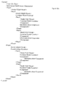
- FIG. 10A is an exemplary XML-based hierarchical combination of components for forming a four-panel window from separate horizontal and vertical panels;
- FIG. 10B is a graphical description of a grammar for defining hierarchical panels
- FIG. 11 is an exemplary layout editor for defining hierarchies of panels
- FIG. 12 is an exemplary component layout grammar representing relationships between various layout components within the system
- FIG. 13 is an entity-relationship diagram for implementing the DSUIs of the present invention without using applets
- FIG. 14 is a message sequence diagram illustrating an initialization of a thin client implementation of the present invention.
- FIG. 15 is a message sequence diagram illustrating the registering of components to receive context information
- FIG. 16 is a message sequence diagram illustrating the building of a component interface
- FIG. 17 is a message sequence diagram illustrating the process of changing context information.
- FIG. 1A is a schematic illustration of a network of computers 100 a , 100 b , and 100 c that share a common information storage system 210 that is accessed via information integration tools and/or application programming interfaces (APIs) 200 .
- Domain-specific user interfaces can be developed using the APIs 200 .
- the exemplary DSUIs of computers 100 a , 100 b , and 100 c are (a) an orthopedics display, (b) an intensive care unit (ICU) display, and (c) an internal medicine display, respectively.
- ICU intensive care unit
- Other DSUIs are also possible, in both the medical domain as well as other domains, where the displays of multiple components need to be kept in synchronization, either (1) in their independent windows or (2) within the bounds of a single integrated window.
- data is generated by many sources and stored within the information storage system 210 in a variety of formats.
- radiological data may be stored in a first database as images and other patient information (e.g., EKG traces or pathological results) information may stored in a second database as at least one of images and text.
- Demographic information may be stored in the same or a different database and is associated with the other patient information.
- read and write access to the data of the information storage system 210 is preferable for at least one component.
- Data preferably is also communicated in a variety of formats (e.g., DICOM, HL7), wherein representations facilitating use by the components directly are the most preferable.
- XML eXtensible Markup Language
- XML provides a simple and robust extendible standard for data representation and exchange. Since XML file are distributed with their own descriptions, XML creates an integrated information object. Thus, XML is (1) structured, (2) extensible and (3) provides validation. XML provides a structure to store and identify information (e.g., patient information in a medical context or suspect/criminal information in a criminal context). The information is structured hierarchically much like objects within the software design. The XML structure can be extended as new information becomes available. XML provides mechanisms to ensure data validity and can be searched directly using query language tools such as XMLSQL.
- FIG. 1B is a data flow model that illustrates the information flow to people or agents (e.g., using a Web browser or other GUI interface). That model includes several high-level steps (each which may be implemented with additional sub-steps or optional steps) including: (1) login, (2) object selection (e.g., patient selection), (3) information display, and (4) user preference management.
- a user's login information can be validated in any manner (e.g., NT authentication or CORBA Security Services).
- an Authentication Agent acts as a gatekeeper between users and data.
- the authentication process allows a user to access user preferences for those features of a DSUI that are customizable. More importantly, though, once authenticated, the user is given the type and scope of access that corresponds to the access rights authorized by the system. Some users may have read-only access, while others have read and write access. Moreover, not all users will be able to see all the data of a system. For example, while hospital administrators may be able to see billing information about a patient's visit, the actual radiographic or diagnostic information is not available. Thus, in one embodiment, the Authentication Agent acts as a continuous middleman during the process of selecting patient records.
- Such selection can be through a number of mechanisms (e.g., by number, by location).
- the Authentication Agent sends the patient record selection information to an Integration Agent. This selection information will be used to build patient information for display and return to the user.
- a Display Agent also accesses that customization information to properly format the results to be displayed.
- users of a standard interface may rearrange that interface in order to suit the user's preference.
- One such rearrangement includes the internationalization of the interface to accommodate languages read right-to-left instead of left-to-right.
- FIG. 1C further illustrates how data is combined from several locations to create the finally rendered layout with the requested data.
- the Integration Agent accesses information from at least one source to build a patient description data block (preferably using XML).
- the interfaces for accessing each data source in its own native standard may be implemented as separate modules or within a single module, but preferably such implementation choices are hidden behind a database abstraction that also hides a physical location of the data.
- this agent utilizes known horizontal component services (e.g., Patient Identification Services provided by CORBAMed).
- a Repository or other centralized data store (including either or both of database- and file-based systems) is utilized.
- the Display Agent accesses a local store of Layout structures (e.g., in an XML-format). These structures are developed by the layout editor (see FIG. 11 ) and stored in a portion of the database that corresponds to display constraints.
- Layout structures e.g., in an XML-format.
- the data and layout are combined (i.e., rendered) by the Rendering component.
- This process combines the retrieved Patient information with the layout information.
- the Rendering component may also utilize context information about the information to be displayed (e.g., a patient's records) before forwarding the complete report to the user.
- the single integrated window is used as a component-based application within a web-based architecture.
- the component architecture allows system developers to create reusable, portable software components that are designed for a specific purpose. Preferably, those components are small, easy to understand and maintain, and fulfill a narrow function within a larger application.
- the applications developer can then have a library of common components that can be used to build up applications rapidly. By keeping the functionality of components narrow, individual components may be used (or reused) by many applications. The resulting componentware can be developed more rapidly and can accommodate portability.
- Java virtual machines and bytecodes increases portability for component-based software systems in an environment of multiple operating systems and diverse development languages.
- higher level components manage the presentation and integration of the lower-level components.
- Cross platform portability is enhanced by a variety of complementary technologies which include Java, Enterprise Java Beans (EJB) and CORBA.
- object models e.g., DCOM
- CORBA provides mechanisms to distribute components among disparate systems.
- services e.g., security, naming, transaction processing
- EJB goes one step further than CORBA by providing a container that acts as a Web Operating System. The container maintains the details of an implementation, providing an additional layer of abstraction for applications.
- Non-applet based technologies are also possible, as described in greater detail below with reference to FIGS. 13-17 .
- One such DSUI is the pulmonologist interface illustrated in FIG. 3 . That DSUI provides a variety of display controls, including six tabs 250 , six panels 260 , and an information status bar 270 . Each of the six tabs 250 corresponds to a page selection (much like selecting tabbed index cards from a box). Each of the six panels 260 is kept in synchronization with the information contained in the status bar 270 , and vice versa.
- the user of the pulmonologist interface changes to a different user using one display control (e.g., by selecting a new visit from a visit list (e.g., implemented as any one of a textual list, a drop-down box, a scrolling list and a set of radio buttons)), all the remaining display controls are controlled to change accordingly (e.g., using messaging as described below).
- a visit list e.g., implemented as any one of a textual list, a drop-down box, a scrolling list and a set of radio buttons
- FIG. 4 is a schematic illustration of a computer system for providing coordinated image and data display.
- a computer 100 implements the method of the present invention, wherein the computer housing 102 houses a motherboard 104 which contains a CPU 106 ; memory 108 (e.g., DRAM, ROM, EPROM, EEPROM, SRAM, SDRAM, and Flash RAM), and other optional special purpose logic devices (e.g., ASICs) or configurable logic devices (e.g., GAL and reprogrammable FPGA).
- the computer 100 also includes plural input devices, (e.g., a keyboard 122 and mouse 124 ), and a display card 110 for controlling monitor 120 .
- the computer system 100 further includes a floppy disk drive 114 ; other removable media devices (e.g., compact disc 119 , tape, and removable magneto-optical media (not shown)); and a hard disk 112 , or other fixed, high density media drives, connected using an appropriate device bus (e.g., a SCSI bus, an Enhanced IDE bus, or a Ultra DMA bus). Also connected to the same device bus or another device bus, the computer 100 may additionally include a compact disc reader 118 , a compact disc reader/writer unit (not shown) or a compact disc jukebox (not shown). Although compact disc 119 is shown in a CD caddy, the compact disc 119 can be inserted directly into CD-ROM drives which do not require caddies. In addition, a printer (not shown) also provides printed listings of reports from the coordinated displays.
- a printer (not shown) also provides printed listings of reports from the coordinated displays.
- the system includes at least one computer readable medium.
- Examples of computer readable media are compact discs 119 , hard disks 112 , floppy disks, tape, magneto-optical disks, PROMs (EPROM, EEPROM, Flash EPROM), DRAM, SRAM, SDRAM, etc.
- the present invention includes software for controlling both the hardware of the computer 100 and for enabling the computer 100 to interact with a human user.
- Such software may include, but is not limited to, device drivers, operating systems and user applications, such as development tools.
- Such computer readable media further includes the computer program product of the present invention for providing coordinated control of display controls or components.
- the computer code devices of the present invention can be any interpreted or executable code mechanism, including but not limited to scripts (including CGI scripts), interpreters, dynamic link libraries, Java classes, Java beans, Active X controls, CCOW-compliant controls and complete executable programs.
- the computer code devices can be downloaded dynamically from a computer network adapter acting as an equivalent to a computer readable medium.
- the number of components that are implemented by a single computer code device, or the number of computer code devices that are required to make up a single component can vary from component-to-component.
- components can be divided by functionality.
- An exemplary division of labor includes (1) components to access and store information in existing hospital systems, (2) components to configure information using XML meta-structures, and (3) components to handle data presentations (e.g., graphing components, image components for displaying images in a variety of formats (e.g., TIFF, GIF, JPEG, bitmap)).
- data presentations e.g., graphing components, image components for displaying images in a variety of formats (e.g., TIFF, GIF, JPEG, bitmap)).
- Such a set of components also allows security to be addressed separately.
- At least two general approaches are possible for Security.
- the security features implemented within components themselves can be used. Basically, this means that security is not an issue of the overall system, but rather of the components utilized by the system. As the security capabilities of components evolve, the system automatically incorporate these components.
- the second approach utilizes a “security component” or uses one of the horizontal services provided by CORBA.
- a security component can take responsibility for validating user access and can mediate communications by components to ensure that security policies are enforced.
- This approach provides a greater level of security but requires increased cooperation from other components. Use of such a security component as well as CORBA services thus needs to be standardized, thereby reducing the ability to utilize 3rd party components.
- a hierarchical component organization also localizes specialized access and display programming. When no access standard is in place, access to the proprietary information can be isolated in a manageable location.
- XML provides mechanisms (e.g., CSS, XSLT, XSL) to render information for display. Those mechanisms allow the same information to be associated with different display characteristics depending on the user and the task. For example, a patient's age may place him/her in a low risk group for one characteristic or disease but in a high risk group for another characteristic or disease.
- components can be configured with an additional level of indirection.
- the name of the tag i.e., the programming variable
- an external specification (within the layoutXML) is created to send the contents of the StudyInstanceUID to the named application.
- other software can be wrapped as long as the parameters to the software are included in a Patient description language (e.g., an XML-based DTD). Because of this additional level of indirection the software can send any instance of a tagged parameter to the software component.
- a component can be programmed to send the most recent, the most recent previous or any other instance of the tagged element to the external component.
- Components within the system of the present invention are assumed to be “wellbehaved.” Accordingly, such components are assumed to enforce data integrity (e.g., concurrency control), utilize authentication (e.g., user-level authentication for patient and exam information), and co-operate with dissimilar component types (CORBA, EJB and DCOM). For components that are not considered to be well behaved or are found to not enforce assumptions of the system, those components are isolated from the other components to prevent data corruption, etc.
- data integrity e.g., concurrency control
- authentication e.g., user-level authentication for patient and exam information
- CORBA, EJB and DCOM co-operate with dissimilar component types
- domain-specific information e.g., patient information
- layout information and context information are combined to form an exemplary DSUI.
- An exemplary structure for patient description language is illustrated in FIGS. 5A and 5B . (By using XML and DOM to hold the patient information, named tags can be associated with components).
- the tabs 250 represent six different information views: (1) Pulmonologist: a view that provides summary information, (2) Drugs: a listing of the patient's medications, (3) Bronchoscopy: views of visible light images of the bronchus, (4) CR: views of CR images, (5) CT: views of CT images, and (6) ECG: views of scanned ECG images.
- each of those tabs is at least partially configurable (e.g., configuring the name tab, the order of the views, and the contents of the view).
- a context may include variables such as ‘ActiveVisit’, ‘Active CRStudy’, ‘Active Series’, etc.
- a component can be configured to track (or remain consistent with) a Context Variable. Utilizing the example of FIG. 3 , information related to a visit on Jan. 11, 1999 is displayed. The first view in the layout, the Pulmonologist view, includes the visit list component, the visit summary component, the study list component and two image display components. Each of those components displays information related to the Jan. 11, 1999 visit. In addition, there is a demographic component that displays information in a status bar that is related to the patient. That component contains information that does not change with the visit. Additional views (not shown), for example the CR view, may also contain information relevant to the Jan. 11, 1999 visit.
- the visit summary component provides information about the Oct. 3, 1999 visit
- the study list component displays a list of studies for the Oct. 3, 1999 visit, the images change to coincide with the study being displayed, and other views that relate to the active visit change.
- views on other pages may be updated as well.
- the CR view (4th tab) remains consistent with the Pulmonologist view (first tab) which contains information relevant to the Oct. 3, 1999 visit after the change.
- some display elements do not change information (e.g., demographic information may not change (and should not change in the illustrated example) between visits for the same person).
- a component can be configured to track a Context Variable or to remain set to a static view. For example, the CR Study viewer above tracks the active visit. The same component can be configured to display only the most recent CR Study. Therefore, when the user changes the active visit, the most recent CR study will always be displayed.
- the structure of the Context Variables is also stored in a hierarchical structure (e.g., a structure similar to the Patient description language).
- the Context Structure contains a variable for each branch in the patient-tree structure. By doing this, the active portion of the patient information can be tracked.
- a component includes three types of information stored in the form of properties: View, Status and Implementation properties.
- this component model is applicable to either (1) an implementation that stores data independently from the components (as described above) or (2) an implementation that stores data with the components (e.g., by storing the configuration of a Java Bean within the Bean itself).
- exemplary properties include: (1) the minimum height and width, MinHeight and MinWidth, respectively, in which the component should be displayed and (2) the optimal background color, BGColor.
- the StatusProperties of components describe how the component should behave in the context of the application.
- Exemplary properties refer to initial setting specifying how the component will be invoked.
- Other status properties describe how the component behaves as the user works. That behavior includes changing the state of the overall system, e.g., by selecting a new active visit from a VisitList Component.
- the Active property is a boolean expression that describes if the component should change with the active status or if it should remain at its initial settings throughout the duration of the session. A “Yes” status indicates that the component should change to follow the settings of other components. A “No” status indicates that the component should remain at its initial settings.
- the TagToFollow property indicates the lowest level tag in the status hierarchy that should be used to modify the component's state.
- the CRImageViewer tracks the status tag CRStudy. Whenever the user selects a different CRStudy (i.e., the status of CRStudy changes) the CRImageViewer will change to track the value of CRStudy.
- the Implementation property describes the actual implementation of the component. It allows the system to create a wrapper to invoke the actual run-time component with the proper parameters.
- the BuilderClass property describes the type of the component. As described above, numerous types (e.g., JavaClasses) of implementation technologies can be used according to the present invention.
- the Path property describes the location of the software to be executed.
- the Parameter property provides any additional start-up parameters that are not specified in StatusProperties.InitialSettings variables (e.g., user identification and passwords).
- the properties are described using an XML-based grammar.
- the view properties and status properties of FIG. 6 are specified with exemplary values for a Study List Component that displays information about CR and Derm Studies.
- the minimum height and width of the components are specified as 180 and 320 pixels, respectively.
- the background color is specified as black.
- Visit and study both utilize the most recent values (i.e., the most recent visit and study, respectively).
- the component is active so that it tracks changes in other components by following the visit variable.
- the highest level of the description language contains identifying information about the patient. It allows demographics and visit information to be expandable therefrom.
- the patient description language is essentially taken from the DICOM view of the ‘real world’. It connects patient information with visits. Visits are used to group care episodes into meaningful chunks, especially in a hospital setting. In an outpatient or clinic setting a more useful grouping might be Diagnostic Code or some other piece of information that groups patient information into episodes of care. For example, it would group information related to a broken leg together and logically separate that information from information about a heart condition.
- This information could also be stored in the format of another standard—like the HL7 RIM model. However, this information does not need to be structured in the same format as it is structured in the database as long as its structure supports the task.
- Context Variables within the application are maintained for points where the patient structure tree branches. If a branch of the tree is maintained for each type of study (e.g., CRStudy, DermStudy, CTStudy), context information can be maintained for these variables since it is known which study is active at any given time. Visit variables contain information about visits (e.g., what group studies a visit corresponds to and what medications were utilized or prescribed).
- CRStudy contains only CR Modality information. It contains some general information about the study and one or more Series elements. The actual images are contained at the Series level.
- the format of the ECGStudy element parallels that of the CRStudy. Again, the highest level contains general information about the study, and there are one or more Series elements. The images are contained at the Series level.
- components that are modality specific are separated from those which are modality independent.
- Modality specific components will generally be those which control physical hardware processes unique to a given modality.
- these components will control transducers or digital I/O interfaces that are necessary for controlling the generation of radiation, mechanical operation or other hardware activities.
- these components should be designed to provide a common interface to the next layer of abstraction that is independent of any modality.
- Modality independent software may include DICOM communications and formatting software components, file management components, systems management and maintenance tools, DICOM modality worklist components, DICOM MPPS components, etc (see FIG. 8 ).
- Such an implementation allows for more general purpose definition of DSUIs through “layouts” for user-interfaces for modalities that are customized to individual needs (e.g., hospital sites or individual medical professionals (e.g., doctors, nurses and medical administrators)).
- the design, creation and modification of custom layouts may be accomplished by end-users working with a layout editor tool.
- New layouts, or management/maintenance layout may further be downloaded using standard web communications protocols. Maintenance layouts may access specialized components that are not accessible to end-users layouts.
- a single page of a layout is described by a hierarchical structure that contains a recursive nesting of panels. This enables a layout to become a sub-layout transparently to the layout, simply by referencing the layout in a “higher level” layout. At each level the panel has display properties to help control and reference the layout. Exemplary properties are illustrated in FIG. 10 B.
- the Title property is an optional property that may be used to associate a name to be displayed as part of a particular layout.
- the Model property is utilized for determining whether the area assigned to the component will be sub-divided. Exemplary types of Model parameters include:
- the Location property can include Directional coordinates such as North, South, East, and West. These indicate which panels are being referenced within the properties.
- various panels can be specified for various functions.
- the Full model may be used for image display.
- the Horizontal Half model may be used to display two comparison images.
- the Vertical Third model may be used to display a study list and two images.
- FIG. 9D If, however, four images were to be displayed on the screen as shown in FIG. 9D , no one component, of the components described above, can be used to provide that functionality directly. Accordingly, the components are used hierarchically to simulate the desired behavior. For example, a Horizontal Half Model where each of the panels contained a Vertical Half Model produces the desired result. An exemplary XML-based description for achieving the four panel display of FIG. 9D is illustrated in FIG. 10 A. Such a layout can then be stored in a library of layouts for re-use later.
- the Layout Editor uses component information (e.g., stored in a local data source).
- the component information describing the layout is stored in an XML structure as described above. Since panels can include panels as components, the layouts can be created rather quickly.
- An exemplary grammar for describing layouts is illustrated in FIG. 12 . Such a grammar describes the elements of a layout and in what order the elements are to appear (including any repetitions or optional elements).
- applets cannot share their display screens with other software modules (e.g., ActiveX Controls, other Applets). This restriction runs counter to allowing the integration of third-party software into a single display environment.
- a first alternate implementation technique includes a native windows application. The basic structure of the software would remain the same but the container would be changed from an applet to an application.
- a second alternate implementation technique includes a thin client, as shown in FIG. 13 . It is this alternate implementation technique that is described in greater detail below. Such a technique may utilize servlets, DHTML, CSS and COM.
- Context-aware applications are referred to hereinafter as “context-aware” applications.
- Integrated sharing is hindered by applications that were not written to expect events or communications from sources other than input devices (e.g., the keyboard and mouse).
- Such applications are referred to hereinafter as “context-unaware” applications.
- sharing can be achieved by utilizing a context or display manager (CDM) that terminates the context-unaware applications and restarts them with the appropriate parameters.
- CDM context or display manager
- One messaging standard that can be used for context-aware applications is CCOW, as discussed above, and tools (e.g., from Sentillion) facilitate creation of such CCOW-based applications.
- the Sentillion development package contains:
- FIG. 13 illustrates a conceptual model using a thin client architecture that distributes services between a client (e.g., using a browser as a client interface) and at least one server.
- a series of HTML pages are used, including a first set of pages that interact with a server (e.g., using a Login Servlet) to validate the user and determine the patient.
- the second set of pages includes plural frames (e.g., 3 frames).
- An exemplary page generated according to the present invention was discussed above with reference to FIG. 3 .
- Each of the frames interacts with the server (using servlets).
- context information is kept within the client and is based on a messaging protocol (e.g., CCOW).
- the client context is maintained within a context server on the client, and the components interact directly with the client context.
- the thin-client is constructed in a two-phase initialization process.
- the first phase of the initialization builds a layout (e.g., using an HTML page) of the components to be used in the DSUI, and in the second phase, the client activates the components thereof.
- a user can interact with each of the control component (e.g., by selecting tabs from the tab bar of FIG. 3 ). This changes the page of information that is being displayed.
- the user can also interact directly with components. These components communicate directly with the context manager or context object.
- FIG. 14 illustrates the sequence diagram for the construction of the component page.
- the client interface is the only software component on the client that need be active in the initial building of the page.
- the client interface requests login information (e.g., (1) authentication code or (2) user id and password) from a user.
- the server e.g., using a login servlet
- authenticates the user and returns a patient selection list and a DisplayLayout that refers to structured display list file (e.g., an XML file) on the server).
- the user selects a patient, and the ActivePatient reference and display layout are sent to the server (e.g., a Frame Servlet).
- the server uses the ActivePatient reference to construct patient information in the patient description language.
- Page layout controls e.g., a set of frames
- Page layout controls of the page skeleton include references to the servlets that will fill in the page layout control areas along with the necessary parameter information.
- three frames i.e., a selector panel frame, a component panel frame, and a demo panel frame
- the SelectorPanel Frame includes a reference to the SelectorPanel Servlet with a display layout parameter.
- the SelectorPanel Servlet sends back a control layout (labeled SelectorPanelHTML) that produces the tab bar at the top of the interface.
- the tab bar is implemented in DHTML so all visual changes to the tab bar take place on the client (e.g., the tabs changing color when the cursor moves over them).
- the component panel frame includes a reference to the ComponentPanel Servlet.
- the client interface activates the ComponentPanel Servlet reference with the ActivePatient and display layout information.
- the ComponentPanel further subdivides its display area to correspond with a specified layout (e.g., divided in vertical or horizontal halves, or vertical or horizontal thirds).
- the ComponentPanel Servlet then inserts a fully qualified reference to the component (e.g., the ActiveX component) in each of the frames that it has created.
- This control layout (labeled ComponentPanelHTML) is returned to the client interface for display.
- the DemoPanel Frame includes a reference to the DemoPanel Servlet.
- the client interface activates the DemoPanel Servlet reference with the ActivePatient parameter.
- the DemoPanel Servlet creates a patient demographic display from the patient description language structure.
- the three servlets process independently and produce display pages (e.g., HTML) as an output. It is very simple to change the look of thin-client by changing the display pages that are output. For example, the tab panel can be moved to the bottom, font and background colors can be easily changed, and frame and font sizes can be modified by simply changing the style sheet.
- display pages e.g., HTML
- FIG. 15 illustrates a sequence diagram that shows the second part of the activation phase.
- the client interface activates the components with the parameters that are specified in their page layout references.
- the context-aware components then join the common context. This enables components to receive later context update messages and request the current context.
- the context is returned as a series of name value pairs.
- FIGS. 16 and 17 illustrate the sequence of steps used in the changes and interactions, respectively.
- the SelectorPanel Servlet and the SelectorPanelFrame create the initial display for the tab bar in the CIMR display.
- the frame contains dynamic control (e.g., DHTML) and all cursor movement and display update occurs within the display through scripts (e.g., through JavaScript-based DHTML).
- each of the tabs is a “submit button” that, when selected by the user, sends a message to a Servlet.
- SelectorPanel Servlet determines which page of the DisplayLayout corresponds with each tab.
- the identification for the DisplayLayout page is inserted into the dynamic control reference that corresponds with the “submit button” related to the tab display.
- the dynamic control takes care of changes in the display (e.g., highlighting the tab when the cursor moves over it, making the selected tab appear to be displayed in the front of the other tabs) and the SelectorPanel display corresponds directly with the ComponentPanel Servlet.
- the client interface activates the ComponentPanel Servlet reference with information that is contained within the “submit button” reference.
- the control layout further subdivides its display area to correspond with the active page (e.g., divided in vertical or horizontal halves, vertical or horizontal thirds).
- the ComponentPanel Servlet then inserts a fully qualified reference to the component in each of the controls that it has created. This control layout is returned to the client interface for display (e.g., as an HTML page).
- the client interface activates the related components in the same manner that is described in FIG. 15 .
- Each of the components joins the active context and gets the active context from the Clinical Context object.
- the second type of user interaction involves the user interacting directly with a component.
- the component not the user, interacts with the shared environment by sending and receiving context information from the context manager or context object.
- the context-changing interaction occurs completely on the client without communication with the server side.
- context-changing may occur with communication to the server (e.g., to record when components were interacted with).
- FIG. 17 illustrates a sequence diagram for a successful context change using a context manager/object.
- the sequence begins when a user selects a new context variable in a component. In this case, the context variable is the visit.
- the context-aware component then begins a protocol to insure that only one application can change context simultaneously and that no changes are lost.
- the context-aware component sends a StartChanges message to the context manager/object. This locks out other applications from beginning a context change and gives the initiating application a blank context area to begin work.
- the application then sends a series of messages to set the new context variables followed by the EndChanges message. When the EndChanges message is received, the context manager/object is free to accept other requests for message changes.
- the context manager/object then sends a message to all other applications that are members of the context (i.e., that have joined the context) that there is a new context pending.
- all applications accept the new context (although other responses are possible).
- the context manager/object sends a message to the initiating component indicating that all applications accepted.
- the initiating component sends a message to the clinical context to replace the current context with the accepted context.
- the clinical context sends out to all members of the context that the new context is now active.
- the applications then request the new context and make the required changes.
- exemplary responses that are not “Accept”.
- the context changer utilizes a token in order to make any changes.
- the context participant that is making changes must be able to deal with busy participants.
- the application must include either code to make a decision regarding whether the context change should proceed or code to prompt the user as to whether or not to proceed with a context change.
- code to make the decision automatically may not be practical.
Landscapes
- Engineering & Computer Science (AREA)
- General Engineering & Computer Science (AREA)
- Theoretical Computer Science (AREA)
- Human Computer Interaction (AREA)
- Physics & Mathematics (AREA)
- General Physics & Mathematics (AREA)
- User Interface Of Digital Computer (AREA)
- Medical Treatment And Welfare Office Work (AREA)
Priority Applications (4)
| Application Number | Priority Date | Filing Date | Title |
|---|---|---|---|
| US09/796,703 US6889363B2 (en) | 2001-03-02 | 2001-03-02 | Interactive multimedia report viewer |
| PCT/US2002/006572 WO2002075512A1 (en) | 2001-03-02 | 2002-03-04 | Interactive multimedia report viewer |
| JP2002057903A JP2002358361A (ja) | 2001-03-02 | 2002-03-04 | 医療情報システム、医療情報表示プログラム、及び医療情報提供方法 |
| JP2008107171A JP4909936B2 (ja) | 2001-03-02 | 2008-04-16 | 医療情報システム |
Applications Claiming Priority (1)
| Application Number | Priority Date | Filing Date | Title |
|---|---|---|---|
| US09/796,703 US6889363B2 (en) | 2001-03-02 | 2001-03-02 | Interactive multimedia report viewer |
Publications (2)
| Publication Number | Publication Date |
|---|---|
| US20020122057A1 US20020122057A1 (en) | 2002-09-05 |
| US6889363B2 true US6889363B2 (en) | 2005-05-03 |
Family
ID=25168839
Family Applications (1)
| Application Number | Title | Priority Date | Filing Date |
|---|---|---|---|
| US09/796,703 Expired - Lifetime US6889363B2 (en) | 2001-03-02 | 2001-03-02 | Interactive multimedia report viewer |
Country Status (3)
| Country | Link |
|---|---|
| US (1) | US6889363B2 (enExample) |
| JP (2) | JP2002358361A (enExample) |
| WO (1) | WO2002075512A1 (enExample) |
Cited By (14)
| Publication number | Priority date | Publication date | Assignee | Title |
|---|---|---|---|---|
| US20040003043A1 (en) * | 2002-06-20 | 2004-01-01 | International Business Machines Corporation | Remote control of document objects in a collaborative environment |
| US20040003054A1 (en) * | 2002-06-28 | 2004-01-01 | International Business Machines Corporation | Systems and methods for transparently accessing Web applications remotely and locally |
| US20040003130A1 (en) * | 2002-06-28 | 2004-01-01 | International Business Machines Corporation | Systems and methods for accessing web services using a tag library |
| US20040001089A1 (en) * | 2002-06-28 | 2004-01-01 | Internationl Business Machines Corporation | Systems and methods for messaging in a multi-frame Web application |
| US20040024841A1 (en) * | 2002-06-28 | 2004-02-05 | International Business Machines Corporation | Systems and methods for displaying and executing web services in multiple content domains |
| US20040034707A1 (en) * | 2002-06-11 | 2004-02-19 | Royer Barry Lynn | System and user interface supporting multiple different concurrent application interoperability methods |
| US20040040027A1 (en) * | 2002-06-20 | 2004-02-26 | Gerold Herold | Processing method for data which is combined to form a plurality of data records, using a plurality of applications |
| US20070050359A1 (en) * | 2005-08-30 | 2007-03-01 | Mckesson Information Solutions, Llc | Method to indicate context synchronization of applications on a computer desktop |
| US20070088525A1 (en) * | 2007-01-05 | 2007-04-19 | Idexx Laboratories, Inc. | Method and System for Representation of Current and Historical Medical Data |
| US7346889B1 (en) * | 2003-01-16 | 2008-03-18 | Oracle International Corporation | Method and system for building message instances |
| US20090007063A1 (en) * | 2006-05-12 | 2009-01-01 | The Mathworks, Inc. | System and method for synchronized workflow management |
| US8099296B2 (en) | 2004-10-01 | 2012-01-17 | General Electric Company | System and method for rules-based context management in a medical environment |
| US20140082532A1 (en) * | 2012-09-14 | 2014-03-20 | Tangentix Limited | Method and Apparatus for Delivery of Interactive Multimedia Content Over a Network |
| US9030491B1 (en) * | 2012-04-18 | 2015-05-12 | The United States Of America As Represented By The Secretary Of The Navy | System and method for displaying data from multiple devices on a single user interface |
Families Citing this family (30)
| Publication number | Priority date | Publication date | Assignee | Title |
|---|---|---|---|---|
| US7000186B1 (en) | 1999-05-03 | 2006-02-14 | Amicas, Inc. | Method and structure for electronically transmitting a text document and linked information |
| US7373600B2 (en) * | 2001-03-27 | 2008-05-13 | Koninklijke Philips Electronics N.V. | DICOM to XML generator |
| US20030088420A1 (en) * | 2001-07-10 | 2003-05-08 | Koninklijke Philips Electronics N.V. | Electronic program guide for processing content-related information configured using a reference information model |
| DE10141834A1 (de) * | 2001-08-27 | 2003-04-03 | Siemens Ag | Datenkonverter |
| US20030211447A1 (en) * | 2001-11-01 | 2003-11-13 | Telecommunications Research Associates | Computerized learning system |
| AU2002348321A1 (en) | 2001-11-21 | 2003-06-10 | Amicas, Inc. | System and methods for real-time worklist service |
| US20050055243A1 (en) * | 2003-06-30 | 2005-03-10 | Dave Arndt | Method and apparatus for managing data received from a medical device |
| JP2005165442A (ja) * | 2003-11-28 | 2005-06-23 | Hitachi Ltd | 医療情報管理システム、医療情報管理方法、および医療情報管理プログラム |
| US20050188311A1 (en) * | 2003-12-31 | 2005-08-25 | Automatic E-Learning, Llc | System and method for implementing an electronic presentation |
| US8442280B2 (en) * | 2004-01-21 | 2013-05-14 | Edda Technology, Inc. | Method and system for intelligent qualitative and quantitative analysis of digital radiography softcopy reading |
| US7996785B2 (en) * | 2004-06-30 | 2011-08-09 | Microsoft Corporation | Systems and methods for integrating application windows in a virtual machine environment |
| FI20045386A0 (fi) * | 2004-10-13 | 2004-10-13 | Onesys Oy | Menetelmä tuottaa lääketieteellistä sisältöä, lääketieteellinen kommunikointijärjestelmä, päätelaite ja tietokoneohjelmatuote |
| JP2006268164A (ja) * | 2005-03-22 | 2006-10-05 | Nomura Research Institute Ltd | 画面情報生成方法、画面情報生成装置および画面情報生成プログラム |
| US20060259513A1 (en) * | 2005-05-10 | 2006-11-16 | Apteryx, Inc. | System and method to submit image requests to DICOM server |
| US7496612B2 (en) * | 2005-07-25 | 2009-02-24 | Microsoft Corporation | Prevention of data corruption caused by XML normalization |
| EP1934849A1 (en) * | 2005-10-06 | 2008-06-25 | General Electric Company | System and method for rules-based context management in a medical environment |
| US20070220035A1 (en) * | 2006-03-17 | 2007-09-20 | Filip Misovski | Generating user interface using metadata |
| EP2115650A2 (en) * | 2007-02-14 | 2009-11-11 | The General Hospital Corporation | Medical laboratory report message gateway |
| JP5287005B2 (ja) * | 2008-07-23 | 2013-09-11 | 株式会社島津製作所 | Mppsゲートウエイ |
| JP5315206B2 (ja) * | 2009-10-22 | 2013-10-16 | 日本電信電話株式会社 | 情報連携システムとその受信側装置及びオブジェクト変換方法 |
| KR101514849B1 (ko) | 2009-11-23 | 2015-04-24 | (의료)길의료재단 | 의료기기 통합 게이트웨이에서 웹기반 원격 관리 지원을 위한 통합 의료관리 인터페이스 시스템 및 그것에 의한 통합 의료관리 방법 |
| KR101093050B1 (ko) * | 2011-04-13 | 2011-12-13 | 주식회사 제론헬스케어 | 의료 영상 데이터 공유 장치, 의료 영상 데이터 공유 시스템 및 의료 영상 데이터 공유 방법 |
| JP6563170B2 (ja) * | 2013-12-09 | 2019-08-21 | キヤノンメディカルシステムズ株式会社 | 医療情報システム及び医療情報提供方法 |
| US10468128B2 (en) * | 2017-04-11 | 2019-11-05 | Canon Medical Systems Corporation | Apparatus and method for presentation of medical data |
| WO2019136070A1 (en) * | 2018-01-02 | 2019-07-11 | Talis Clinical LLC | Improved healthcare interoperability environment system |
| US12367968B2 (en) | 2018-01-03 | 2025-07-22 | Talis Clinical LLC | Continuous improvement tool |
| US11150791B1 (en) * | 2020-01-15 | 2021-10-19 | Navvis & Company, LLC | Unified ecosystem experience for managing multiple healthcare applications from a common interface with trigger-based layout control |
| CN118284957A (zh) | 2021-11-26 | 2024-07-02 | 信越工程株式会社 | 激光剥离方法、受体基板的制造方法、激光剥离装置及光掩模 |
| CN114461161B (zh) * | 2022-01-19 | 2023-07-07 | 巴可(苏州)医疗科技有限公司 | 显示器集成QAweb的方法及应用该方法的医疗显示器 |
| US20240154808A1 (en) * | 2022-11-03 | 2024-05-09 | Change Healthcare Holdings, Llc | Systems and methods of trace id validation and trust |
Citations (16)
| Publication number | Priority date | Publication date | Assignee | Title |
|---|---|---|---|---|
| US4567515A (en) | 1983-04-20 | 1986-01-28 | Measuronics Corporation | Multiple image generation and analysis system |
| US5452416A (en) | 1992-12-30 | 1995-09-19 | Dominator Radiology, Inc. | Automated system and a method for organizing, presenting, and manipulating medical images |
| US5600574A (en) * | 1994-05-13 | 1997-02-04 | Minnesota Mining And Manufacturing Company | Automated image quality control |
| US5712995A (en) * | 1995-09-20 | 1998-01-27 | Galileo Frames, Inc. | Non-overlapping tiling apparatus and method for multiple window displays |
| US5803914A (en) | 1993-04-15 | 1998-09-08 | Adac Laboratories | Method and apparatus for displaying data in a medical imaging system |
| US5954650A (en) | 1996-11-13 | 1999-09-21 | Kabushiki Kaisha Toshiba | Medical image processing apparatus |
| US6063030A (en) | 1993-11-29 | 2000-05-16 | Adalberto Vara | PC based ultrasound device with virtual control user interface |
| US6081267A (en) | 1998-11-19 | 2000-06-27 | Columbia Scientific Incorporated | Computerized apparatus and method for displaying X-rays and the like for radiological analysis and manipulation and transmission of data |
| US6115626A (en) * | 1998-03-26 | 2000-09-05 | Scimed Life Systems, Inc. | Systems and methods using annotated images for controlling the use of diagnostic or therapeutic instruments in instruments in interior body regions |
| US6192266B1 (en) * | 1998-03-26 | 2001-02-20 | Boston Scientific Corporation | Systems and methods for controlling the use of diagnostic or therapeutic instruments in interior body regions using real and idealized images |
| US6272469B1 (en) | 1998-11-25 | 2001-08-07 | Ge Medical Systems Global Technology Company, Llc | Imaging system protocol handling method and apparatus |
| US20010020243A1 (en) * | 1996-12-06 | 2001-09-06 | Srinivasa R. Koppolu | Object-oriented framework for hyperlink navigation |
| US6310631B1 (en) * | 1996-04-26 | 2001-10-30 | International Business Machines Corporation | User interface control for creating split panes in a single window |
| US6342907B1 (en) * | 1998-10-19 | 2002-01-29 | International Business Machines Corporation | Specification language for defining user interface panels that are platform-independent |
| US6401138B1 (en) * | 1996-10-28 | 2002-06-04 | Koninklijke Philips Electronics N.V. | Interface for patient context sharing and application switching |
| US6476833B1 (en) * | 1999-03-30 | 2002-11-05 | Koninklijke Philips Electronics N.V. | Method and apparatus for controlling browser functionality in the context of an application |
-
2001
- 2001-03-02 US US09/796,703 patent/US6889363B2/en not_active Expired - Lifetime
-
2002
- 2002-03-04 JP JP2002057903A patent/JP2002358361A/ja active Pending
- 2002-03-04 WO PCT/US2002/006572 patent/WO2002075512A1/en not_active Ceased
-
2008
- 2008-04-16 JP JP2008107171A patent/JP4909936B2/ja not_active Expired - Lifetime
Patent Citations (16)
| Publication number | Priority date | Publication date | Assignee | Title |
|---|---|---|---|---|
| US4567515A (en) | 1983-04-20 | 1986-01-28 | Measuronics Corporation | Multiple image generation and analysis system |
| US5452416A (en) | 1992-12-30 | 1995-09-19 | Dominator Radiology, Inc. | Automated system and a method for organizing, presenting, and manipulating medical images |
| US5803914A (en) | 1993-04-15 | 1998-09-08 | Adac Laboratories | Method and apparatus for displaying data in a medical imaging system |
| US6063030A (en) | 1993-11-29 | 2000-05-16 | Adalberto Vara | PC based ultrasound device with virtual control user interface |
| US5600574A (en) * | 1994-05-13 | 1997-02-04 | Minnesota Mining And Manufacturing Company | Automated image quality control |
| US5712995A (en) * | 1995-09-20 | 1998-01-27 | Galileo Frames, Inc. | Non-overlapping tiling apparatus and method for multiple window displays |
| US6310631B1 (en) * | 1996-04-26 | 2001-10-30 | International Business Machines Corporation | User interface control for creating split panes in a single window |
| US6401138B1 (en) * | 1996-10-28 | 2002-06-04 | Koninklijke Philips Electronics N.V. | Interface for patient context sharing and application switching |
| US5954650A (en) | 1996-11-13 | 1999-09-21 | Kabushiki Kaisha Toshiba | Medical image processing apparatus |
| US20010020243A1 (en) * | 1996-12-06 | 2001-09-06 | Srinivasa R. Koppolu | Object-oriented framework for hyperlink navigation |
| US6115626A (en) * | 1998-03-26 | 2000-09-05 | Scimed Life Systems, Inc. | Systems and methods using annotated images for controlling the use of diagnostic or therapeutic instruments in instruments in interior body regions |
| US6192266B1 (en) * | 1998-03-26 | 2001-02-20 | Boston Scientific Corporation | Systems and methods for controlling the use of diagnostic or therapeutic instruments in interior body regions using real and idealized images |
| US6342907B1 (en) * | 1998-10-19 | 2002-01-29 | International Business Machines Corporation | Specification language for defining user interface panels that are platform-independent |
| US6081267A (en) | 1998-11-19 | 2000-06-27 | Columbia Scientific Incorporated | Computerized apparatus and method for displaying X-rays and the like for radiological analysis and manipulation and transmission of data |
| US6272469B1 (en) | 1998-11-25 | 2001-08-07 | Ge Medical Systems Global Technology Company, Llc | Imaging system protocol handling method and apparatus |
| US6476833B1 (en) * | 1999-03-30 | 2002-11-05 | Koninklijke Philips Electronics N.V. | Method and apparatus for controlling browser functionality in the context of an application |
Cited By (28)
| Publication number | Priority date | Publication date | Assignee | Title |
|---|---|---|---|---|
| US20040034707A1 (en) * | 2002-06-11 | 2004-02-19 | Royer Barry Lynn | System and user interface supporting multiple different concurrent application interoperability methods |
| US20040003043A1 (en) * | 2002-06-20 | 2004-01-01 | International Business Machines Corporation | Remote control of document objects in a collaborative environment |
| US20040040027A1 (en) * | 2002-06-20 | 2004-02-26 | Gerold Herold | Processing method for data which is combined to form a plurality of data records, using a plurality of applications |
| US8645862B2 (en) | 2002-06-28 | 2014-02-04 | International Business Machines Corporation | Displaying and executing web services in multiple content domains |
| US7792929B2 (en) | 2002-06-28 | 2010-09-07 | International Business Machines Corporation | Systems and methods for transparently accessing web applications remotely and locally |
| US20040001089A1 (en) * | 2002-06-28 | 2004-01-01 | Internationl Business Machines Corporation | Systems and methods for messaging in a multi-frame Web application |
| US20040003130A1 (en) * | 2002-06-28 | 2004-01-01 | International Business Machines Corporation | Systems and methods for accessing web services using a tag library |
| US7200818B2 (en) | 2002-06-28 | 2007-04-03 | International Business Machines Corporation | Systems and methods for messaging in a multi-frame Web application |
| US20040024841A1 (en) * | 2002-06-28 | 2004-02-05 | International Business Machines Corporation | Systems and methods for displaying and executing web services in multiple content domains |
| US20040003054A1 (en) * | 2002-06-28 | 2004-01-01 | International Business Machines Corporation | Systems and methods for transparently accessing Web applications remotely and locally |
| US7426545B2 (en) * | 2002-06-28 | 2008-09-16 | International Business Machines Corporation | Systems and methods for transparently accessing Web applications remotely and locally |
| US20090164563A1 (en) * | 2002-06-28 | 2009-06-25 | International Business Machines Corporation | Systems and Methods for Transparently Accessing Web Applications Remotely and Locally |
| US7346889B1 (en) * | 2003-01-16 | 2008-03-18 | Oracle International Corporation | Method and system for building message instances |
| US8099296B2 (en) | 2004-10-01 | 2012-01-17 | General Electric Company | System and method for rules-based context management in a medical environment |
| US20070050359A1 (en) * | 2005-08-30 | 2007-03-01 | Mckesson Information Solutions, Llc | Method to indicate context synchronization of applications on a computer desktop |
| US7752178B2 (en) | 2005-08-30 | 2010-07-06 | Mckesson Information Solutions Llc | Method to indicate context synchronization of applications on a computer desktop |
| US8656352B2 (en) | 2006-05-12 | 2014-02-18 | The Mathworks, Inc. | System and method for synchronized workflow management |
| US20090007063A1 (en) * | 2006-05-12 | 2009-01-01 | The Mathworks, Inc. | System and method for synchronized workflow management |
| US8261233B2 (en) * | 2006-05-12 | 2012-09-04 | The Mathworks, Inc. | System and method for synchronized workflow management |
| US8579814B2 (en) | 2007-01-05 | 2013-11-12 | Idexx Laboratories, Inc. | Method and system for representation of current and historical medical data |
| US8585590B2 (en) | 2007-01-05 | 2013-11-19 | Idexx Laboratories, Inc. | Method and system for representation of current and historical medical data |
| US20070198301A1 (en) * | 2007-01-05 | 2007-08-23 | Idexx Laboratories, Inc. | Method and System for Representation of Current and Historical Medical Data |
| US20070088525A1 (en) * | 2007-01-05 | 2007-04-19 | Idexx Laboratories, Inc. | Method and System for Representation of Current and Historical Medical Data |
| US11551789B2 (en) | 2007-01-05 | 2023-01-10 | Idexx Laboratories, Inc. | Method and system for representation of current and historical medical data |
| USD1072841S1 (en) | 2007-01-05 | 2025-04-29 | Idexx Laboratories, Inc. | Display screen or portion thereof with a graphical user interface for reporting medical data |
| US9030491B1 (en) * | 2012-04-18 | 2015-05-12 | The United States Of America As Represented By The Secretary Of The Navy | System and method for displaying data from multiple devices on a single user interface |
| US20140082532A1 (en) * | 2012-09-14 | 2014-03-20 | Tangentix Limited | Method and Apparatus for Delivery of Interactive Multimedia Content Over a Network |
| US9367213B2 (en) * | 2012-09-14 | 2016-06-14 | Tangentix Limited | Method and apparatus for delivery of interactive multimedia content over a network |
Also Published As
| Publication number | Publication date |
|---|---|
| US20020122057A1 (en) | 2002-09-05 |
| WO2002075512A1 (en) | 2002-09-26 |
| JP4909936B2 (ja) | 2012-04-04 |
| JP2008204478A (ja) | 2008-09-04 |
| JP2002358361A (ja) | 2002-12-13 |
Similar Documents
| Publication | Publication Date | Title |
|---|---|---|
| US6889363B2 (en) | Interactive multimedia report viewer | |
| US6889359B1 (en) | Method for providing a visual representation of dynamic HTML table attributes | |
| EP1350180B1 (en) | Authoring arbitrary xml documents using dhtml and xslt | |
| US6718515B1 (en) | Method of populating a dynamic HTML table from a set of data objects through a common interface | |
| US6851088B1 (en) | Conditional highlighting of given cells in a dynamic HTML table | |
| US8527943B1 (en) | System and method of application development | |
| US9152434B2 (en) | Enterprise user interface customization | |
| US6275227B1 (en) | Computer system and method for controlling the same utilizing a user interface control integrated with multiple sets of instructional material therefor | |
| Boxwala et al. | Toward a representation format for sharable clinical guidelines | |
| US20050033717A1 (en) | System and method for building a distributed internet application | |
| Hooda et al. | Health Level-7 compliant clinical patient records system | |
| US8887090B2 (en) | Surfacing of detailed information via formlets | |
| Gambino et al. | A framework for data-driven adaptive GUI generation based on DICOM | |
| Brandt et al. | Reengineering a database for clinical trials management: lessons for system architects | |
| US20050091601A1 (en) | Interaction design system | |
| Dias et al. | Enhancing data science interoperability: an innovative system for managing openEHR structures | |
| Brelstaff et al. | Internet patient records: new techniques | |
| Laird et al. | Design and implementation of an Internet-based medical image viewing system | |
| Riva et al. | A development environment for knowledge-based medical applications on the world-wide web | |
| Hurlen et al. | The basic principles of the synapses federated healthcare record server | |
| Hinds et al. | WHAM!: a forms constructor for medical record access via the World Wide Web | |
| Moshfeghi et al. | XML in a multi-tier Java/CORBA architecture | |
| Paterno et al. | The role of HCI models in service front-end development | |
| Baumgärtner | Framework Design | |
| Ghanbari | TelecarePLUS: Bridging the gap between providers and patients through telemedicine |
Legal Events
| Date | Code | Title | Description |
|---|---|---|---|
| AS | Assignment |
Owner name: ARIZONA BOARD OF REGENTS ON BEHALF OF THE UNIVERSI Free format text: ASSIGNMENT OF ASSIGNORS INTEREST;ASSIGNOR:MALONEY, KRISELLEN;REEL/FRAME:011988/0438 Effective date: 20010624 |
|
| STCF | Information on status: patent grant |
Free format text: PATENTED CASE |
|
| FEPP | Fee payment procedure |
Free format text: PAYER NUMBER DE-ASSIGNED (ORIGINAL EVENT CODE: RMPN); ENTITY STATUS OF PATENT OWNER: LARGE ENTITY Free format text: PAYOR NUMBER ASSIGNED (ORIGINAL EVENT CODE: ASPN); ENTITY STATUS OF PATENT OWNER: LARGE ENTITY |
|
| FPAY | Fee payment |
Year of fee payment: 4 |
|
| FPAY | Fee payment |
Year of fee payment: 8 |
|
| FPAY | Fee payment |
Year of fee payment: 12 |