US6886597B2 - Proportional electrovalve for motor cooling liquid circuit - Google Patents
Proportional electrovalve for motor cooling liquid circuit Download PDFInfo
- Publication number
- US6886597B2 US6886597B2 US10/450,180 US45018003A US6886597B2 US 6886597 B2 US6886597 B2 US 6886597B2 US 45018003 A US45018003 A US 45018003A US 6886597 B2 US6886597 B2 US 6886597B2
- Authority
- US
- United States
- Prior art keywords
- valve
- solenoid valve
- core plunger
- shutter
- pushrod
- Prior art date
- Legal status (The legal status is an assumption and is not a legal conclusion. Google has not performed a legal analysis and makes no representation as to the accuracy of the status listed.)
- Expired - Lifetime
Links
- 239000000110 cooling liquid Substances 0.000 title claims description 15
- 230000000712 assembly Effects 0.000 claims description 5
- 238000000429 assembly Methods 0.000 claims description 5
- 238000001914 filtration Methods 0.000 claims description 5
- 230000002093 peripheral effect Effects 0.000 claims description 5
- 230000007423 decrease Effects 0.000 claims description 4
- 230000001747 exhibiting effect Effects 0.000 claims description 4
- 229920001971 elastomer Polymers 0.000 claims description 3
- 239000000806 elastomer Substances 0.000 claims description 3
- 239000000463 material Substances 0.000 claims description 3
- 230000004044 response Effects 0.000 claims description 3
- 230000006835 compression Effects 0.000 claims description 2
- 238000007906 compression Methods 0.000 claims description 2
- 230000000284 resting effect Effects 0.000 claims description 2
- 230000007935 neutral effect Effects 0.000 abstract 1
- 239000012530 fluid Substances 0.000 description 13
- 239000007788 liquid Substances 0.000 description 7
- 238000010276 construction Methods 0.000 description 5
- 230000004907 flux Effects 0.000 description 3
- 238000007789 sealing Methods 0.000 description 3
- 238000002485 combustion reaction Methods 0.000 description 2
- 239000013529 heat transfer fluid Substances 0.000 description 2
- 239000004952 Polyamide Substances 0.000 description 1
- 230000008901 benefit Effects 0.000 description 1
- 230000008859 change Effects 0.000 description 1
- 239000012809 cooling fluid Substances 0.000 description 1
- 238000000034 method Methods 0.000 description 1
- 230000003071 parasitic effect Effects 0.000 description 1
- 229920002647 polyamide Polymers 0.000 description 1
- 230000009467 reduction Effects 0.000 description 1
Images


Classifications
-
- F—MECHANICAL ENGINEERING; LIGHTING; HEATING; WEAPONS; BLASTING
- F16—ENGINEERING ELEMENTS AND UNITS; GENERAL MEASURES FOR PRODUCING AND MAINTAINING EFFECTIVE FUNCTIONING OF MACHINES OR INSTALLATIONS; THERMAL INSULATION IN GENERAL
- F16K—VALVES; TAPS; COCKS; ACTUATING-FLOATS; DEVICES FOR VENTING OR AERATING
- F16K31/00—Actuating devices; Operating means; Releasing devices
- F16K31/02—Actuating devices; Operating means; Releasing devices electric; magnetic
- F16K31/06—Actuating devices; Operating means; Releasing devices electric; magnetic using a magnet, e.g. diaphragm valves, cutting off by means of a liquid
- F16K31/0644—One-way valve
- F16K31/0655—Lift valves
-
- F—MECHANICAL ENGINEERING; LIGHTING; HEATING; WEAPONS; BLASTING
- F16—ENGINEERING ELEMENTS AND UNITS; GENERAL MEASURES FOR PRODUCING AND MAINTAINING EFFECTIVE FUNCTIONING OF MACHINES OR INSTALLATIONS; THERMAL INSULATION IN GENERAL
- F16K—VALVES; TAPS; COCKS; ACTUATING-FLOATS; DEVICES FOR VENTING OR AERATING
- F16K1/00—Lift valves or globe valves, i.e. cut-off apparatus with closure members having at least a component of their opening and closing motion perpendicular to the closing faces
- F16K1/32—Details
- F16K1/34—Cutting-off parts, e.g. valve members, seats
- F16K1/44—Details of seats or valve members of double-seat valves
-
- Y—GENERAL TAGGING OF NEW TECHNOLOGICAL DEVELOPMENTS; GENERAL TAGGING OF CROSS-SECTIONAL TECHNOLOGIES SPANNING OVER SEVERAL SECTIONS OF THE IPC; TECHNICAL SUBJECTS COVERED BY FORMER USPC CROSS-REFERENCE ART COLLECTIONS [XRACs] AND DIGESTS
- Y10—TECHNICAL SUBJECTS COVERED BY FORMER USPC
- Y10T—TECHNICAL SUBJECTS COVERED BY FORMER US CLASSIFICATION
- Y10T137/00—Fluid handling
- Y10T137/8593—Systems
- Y10T137/86493—Multi-way valve unit
- Y10T137/86718—Dividing into parallel flow paths with recombining
- Y10T137/86759—Reciprocating
- Y10T137/86767—Spool
Definitions
- the present invention relates to a solenoid valve (electrovalve) that has a proportional response to a signal supplied in the form of an inductor current to the coil of the electromagnet on which said solenoid valve is based.
- a solenoid valve is intended to be used to control the flow rate of the cooling fluid in a motor vehicle engine.
- the flow rate of heat transfer fluid in a combustion engine has been controlled by a device of the valve type that is closed when the liquid is cold, and that opens when the liquid begins to heat up.
- the opening of the valve is therefore linked to the temperature of the cooling liquid.
- the efficiency and operation of the motor vehicle engine, and of all the associated functions using the heat transfer fluid may, however, be improved by using a device that is not autonomous, unlike current practice, but that allows the fluid flow rate to be controlled on the basis of the engine operating conditions.
- the object of this invention is to propose a device that can be controlled by the vehicle computer, allowing a great many parameters to be taken into consideration in the logic of controlling the flow rate of the cooling liquid.
- the solenoid valve of the invention will be able to be controlled more finely using parameters such as the engine speed, the vehicle speed, the temperature of the engine at various locations, or alternatively the switching-on of auxiliary systems such as the climate control system.
- a further objective of the invention is to propose, in one possible configuration of the invention, a device that uses an electromagnet in which the geometry of the various parts makes it possible to obtain a thrust force that is relatively constant regardless of the magnitude of the air gap, for a given supply current amplitude.
- the configurations proposed by the invention will not dictate there having to be a minimum flow rate and will, by contrast, allow the valve to be closed completely.
- the solenoid valve of the invention will be able to be built as a functional module of the cartridge type that can be inserted either into a specific interface unit or into an existing part of the motor vehicle.
- the solenoid valve of the invention offers a response that is proportional to an inductor current powering the inductor coil of its electromagnet, essentially comprises such a coil, surrounding an axially moving core plunger to which there is secured a pushrod sliding in a pole piece of the fixed magnetic circuit and collaborating with the inductor coil. It actuates a valve comprising at least one valve shutter collaborating with a seat so as to open and close the valve, return means giving this valve shutter a stable position of rest with respect to the seat when the inductor current is zero.
- Each valve shutter is coaxial with the pushrod and actuated by it. According to a main feature, the mechanical connection between the shaft of each valve shutter and either the shaft of the adjacent valve shutter or the pushrod is reduced to a point contact.
- This specific feature offers an advantage that is of primary importance at the time of assembly because there can be a slight misalignment due to assembly, particularly when there is more than one valve shutter. With this type of construction, correct operation of the valve shutters is unaffected by this misalignment, because of the aforementioned connection between the various parts, which connection is not rigid.
- each valve shutter slides with respect to a valve body in which are made at least one fluid inlet orifice and at least one fluid exhaust orifice, and in which the valve seat is formed.
- valve shutters When several valve shutters (generally two) are arranged one after the other, the point contact applies, on the one hand, between the pushrod and a first valve shutter the body of which is placed in contact with the electromagnet and, on the other hand, between the first and second valve shutters.
- the means for returning the valve shutter away from the seat consist of a coil spring arranged around the shaft of the valve shutter, in an axial housing thereof, said spring resting on the central part of the seat for the valve shutter.
- valve bodies are fixed with respect to a casing surrounding the solenoid valve assembly.
- the contact pressure with each of the aforementioned adjacent axial elements is provided at the moving valve shutter, which in actual fact transmits the force applied to it by the spring regardless of the magnetic force conveyed by the pushrod.
- valve shutter and the valve body exhibit symmetry of revolution, the shaft of each valve shutter sliding axially in the valve body the seat of which is orientated roughly at right angles to said axis.
- the external wall of the valve body has a peripheral housing designed to house an O-ring.
- This O-ring allows each valve body to be fixed to the external casing that forms the jacket of the solenoid valve of the invention. This is as true in the case where the device is mounted in a special-purpose interface unit as it is when it is mounted in an existing part of the motor vehicle, if this is the option chosen.
- each valve shutter exhibits a seal that can be termed an internal seal, that provides a very small flow rate of cooling liquid when the device is in the closed position.
- This is an elastomer seal overmolded onto the portion of its peripheral wall that is designed to come into contact with the seat.
- the solenoid valve of the invention in fact comprises two coaxial valve shutters the valve bodies of which are superposed along the axis of the pushrod.
- This double-valve-shutter principle makes it possible to minimize the forces needed to control the solenoid valve. This construction also makes it possible to reduce the weight and power consumption of the device.
- the two valve shutters are kept by the return means away from their respective seats when the inductor current is zero.
- the two assemblies made up of the valve shutters and of their respective bodies are screwed together.
- Such an assembly ensures the possibility of precise adjustment between the two assembles, so as to obtain simultaneous closure of the two valve shutters, and therefore a very low flow rate of cooling liquid when the device is in the closed position.
- the assemblies made up of the valve shutters and of their respective bodies are identical and made of the same material.
- the main material of which these assemblies are made is polyamide.
- the device described hereinabove is normally open, which means that, when the electrical power supply to the device is cut off, the solenoid valve returns to the position in which the valve shutters are wide open, thus reducing the risk of combustion engine failure.
- the magnetic circuit collaborating with the inductor coil comprises, apart from the moving core plunger, two fixed pole pieces appearing to be coaxial with the core plunger, and between which the latter slides, the pole piece in which the pushrod slides and the core plunger exhibiting, in the region defining their air gap, respective shapes making it possible to obtain a thrust force that is substantially constant regardless of the distance of the air gap, for a given magnitude of the inductor current.
- This configuration makes it possible to achieve optimum precision and optimum control of the flow rate, and precision on the position of the moving parts of the device in intermediate states between wide open and fully closed.
- the moving magnetic core plunger has cylindrical geometry, the pole piece in which the pushrod slides being equipped on its side facing said core plunger with a cylindrical housing of a diameter greater than that of the core plunger, defining two perpendicular orientations for the air gap when the core plunger enters said housing.
- the solenoid valve of the invention may have just one valve shutter sliding in its valve body. It may also be provided with a magnetic circuit collaborating with the inductor coil which comprises, apart from the moving core plunger, two fixed pole pieces appearing to be coaxial with said core plunger, and between which the latter slides, the pole piece in which the pushrod slides and the moving core plunger exhibiting, in the region defining their air gap, respective shapes making it possible to obtain a thrust force that increases when the air gap distance decreases, for a given magnitude of the inductor current.
- the electromagnet is modified to increase the force supplied near valve closure, so as to reduce the leakage in the valve-closed position.
- the facing surfaces belonging to the pole piece in which the pushrod slides and belonging to the moving core plunger, and defining their air gap are of parallel appearance.
- the invention also has other functional possibilities aimed at optimizing its behavior.
- the initial position of the moving core plunger when the inductor current is zero, can be adjusted using a screw accessible from outside the solenoid valve casing and that alters the compression of a spring arranged between it and the moving core plunger, the return force of said spring being exerted axially toward the pole piece in which the pushrod slides.
- This construction in particular allows the device to be calibrated when it is being assembled, or recalibrated in the event of a problem or a change to the operation.
- the moving core plunger also comprises means for filtering out external vibrations likely to cause the moving parts to move in a way unrelated to the operating current.
- said filtering means consist of an axial duct made in the moving core plunger, connecting two chambers that are defined between the latter and the fixed pole pieces, inside the coil, said chambers being filled with a cooling liquid that passes from one chamber to the other via the duct in the core plunger should the latter move.
- the solenoid valve of the invention can actually be used in environments that are potentially subject to strong vibrations. These external vibrations are of course parasitic to the operation of the device and have to be filtered out. For this, use is made of the possibility of passing fluid between the two chambers, by means of what has come to be known as a hydraulic restriction in the electromagnet. As the core plunger moves, the cooling liquid is forced to pass from one chamber to the other, and the cross section of the duct slows the rate of travel of the core plunger. The passage cross section of said duct in the core plunger is chosen to filter out the high-speed movements resulting from the vibrations encountered and likely to disturb the correct operation of the device.
- the solenoid valve of the invention can be built into a device for controlling the flow rate of a fluid, either in the form of a cartridge, by forming an external component that can be incorporated into a special-purpose interface, or directly into the structure of the engine of the motor vehicle, for example as a replacement for a valve of the prior art.
- FIG. 1 shows a solenoid valve viewed in section, in its two-valve-shutter configuration, in the open position;
- FIG. 2 is similar to FIG. 1 , the solenoid valve there being depicted in the closed position;
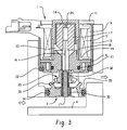
- FIG. 3 depicts a configuration with just one valve shutter.
- the solenoid valve of the invention is made up schematically of an electromagnet ( 1 ), of two shutter valves ( 2 ) and ( 3 ), all contained in a casing ( 4 ) adopting, for example, the form of a cartridge.
- the electromagnet ( 1 ) proper is made up of a coil ( 5 ), at the periphery of which there is an overmolded jacket ( 6 ) and which collaborates with a magnetic circuit made up of the following elements: a moving core plunger ( 7 ) axially surrounded by two pole pieces, namely a upper pole piece ( 8 ) and a lower pole piece ( 9 ), an external magnetic field frame ( 10 ), all held in place by a flange ( 11 ).
- the magnetic core plunger ( 7 ) can be calibrated using a calibrating screw ( 12 ) that compresses/decompresses a spring ( 13 ) inserted in the cylindrical-shaped housings made respectively in the moving core plunger ( 7 ) and the screw ( 12 ), and that together form a chamber known as the upper chamber ( 14 ).
- the moving core plunger ( 7 ) is separated from the upper pole piece ( 8 ) by a ring ( 15 ) intended to facilitate the sliding movement of one with respect to the other.
- the moving core plunger ( 7 ) exhibits, protruding from its opposite end to the one that has the spring ( 13 ), a pushrod ( 16 ) that slides inside the lower pole piece ( 9 ) and collaborates with the upper part of the valve shutter ( 2 ) adjacent to the electromagnet ( 1 ), via point contact between its end and the upper end of the shaft ( 17 ) of said valve shutter ( 2 ).
- the electromagnet ( 1 ) is also made up of other conventional functional elements of the following type: tube ( 18 ), field frame ( 19 ) and various operating seals.
- a seal ( 20 ) is placed between the calibrating screw ( 12 ) and the pole piece ( 8 ).
- the lower pole piece ( 9 ) has a housing designed to accommodate an O-ring ( 21 ) providing sealing with the lower structure of the electromagnet.
- the moving assembly of the electromagnet ( 1 ) which assembly consists of the moving core plunger ( 8 ) and of the pushrod ( 16 ) obviously has the function of moving the valves ( 2 ) and ( 3 ), each consisting of a valve shutter ( 25 , 26 ) attached to an axial shaft ( 17 , 27 ), said shaft sliding in the central body ( 28 , 29 ) of each of the valve shutters ( 2 , 3 ) in which body there is, in particular, the seat of each of these valves.
- the central part of said bodies ( 28 , 29 ), in which part the shafts ( 17 , 27 ) slide, is in fact in the form of a ring ( 30 , 31 ) on which there rests the spring ( 32 , 33 ) holding the valve shutter ( 25 , 26 ) away from the seat in the valve body ( 28 , 29 ).
- These bodies ( 28 , 29 ) have an external housing able to accommodate O-rings ( 34 , 35 ) providing sealing between said bodies ( 28 , 29 ) and the casing ( 4 ) and assisting with the fitting thereof.
- valve shutters ( 25 , 26 ) portion of the peripheral surface of the valve shutters ( 25 , 26 ) that is intended to come into contact with the seat of the valve body ( 28 , 29 ) is fitted with an overmolded elastic seal ( 36 , 37 ) providing a very small flow rate of cooling liquid when the device is in the closed position.
- the black arrows indicate the passage of the fluid.
- the device of the invention therefore comprises three distinct groups of openings, the upper and lower groups allowing cooling liquid to enter the device, while the middle group allows the cooling liquid to leave the device.
- the flow of liquid entering the solenoid valve through the inlet in the external body ( 4 ) at a pressure P 1 is split into two; part of the flow passes through the orifice formed between the body ( 28 ) of the upper valve ( 2 ) and the upper valve shutter ( 25 ) covered with the seal ( 36 ). The other part of the flow passes through the orifice formed by the body ( 29 ) of the lower valve ( 3 ) and the lower valve shutter ( 26 ) equipped with its elastomer seal ( 37 ).
- the fluid experiences a pressure drop ⁇ P due mainly to the restrictions of cross sections S formed by the orifices defined by the two seats in the two valve bodies ( 28 , 29 ) and the two valve shutters ( 25 , 26 ).
- ⁇ P P 1 ⁇ P 2 .
- the coil is powered by an electric signal.
- This power signal may be of two types: either a controlled current, or a voltage chopped at a fixed frequency with control of the duty cycle for opening, using procedures known per se.
- the geometry of the various parts of the electromagnetic subassembly is chosen so that, for a given amplitude of the power supply signal to the coil ( 5 ), there corresponds a relatively constant thrust force of the moving subassembly ( 7 , 16 ) of the electromagnet ( 1 ) on the moving parts ( 17 , 25 , 26 , 27 ) of the valve regardless of the magnitude of the travel.
- the thrust force exerted by the pushrod may in any event be controlled by varying the power supply signal.
- the various elements in the moving subassembly ( 7 , 16 ) of the electromagnet ( 1 ) and the moving parts ( 17 , 25 , 26 , 27 ) of the valve are kept in contact with one another by the force exerted by the springs ( 32 , 33 ).
- the moving subassembly of the electromagnet ( 7 , 16 ) exerts no force on the moving subassembly ( 17 , 25 , 26 , 27 ) of the valve, which therefore finds itself in the wide open position.
- the moving subassembly ( 17 , 25 , 26 , 27 ) of the valve places itself in an intermediate position of openness.
- the force exerted by the moving subassembly ( 7 , 16 ) of the electromagnet and its spring ( 13 ) on the moving subassembly ( 17 , 25 , 26 , 27 ) of the valve is equal, but in the opposite direction to the force exerted by the resultant of the springs on the moving subassembly ( 17 , 25 , 26 , 27 ) of the valve.
- Control of the supply signal therefore makes it possible to control precisely the position of the two valve shutters ( 25 , 26 ) with respect to their respective seat, to control the passage cross section offered to the fluid and therefore to control the volumetric flow rate of fluid passing through the device.
Landscapes
- Engineering & Computer Science (AREA)
- General Engineering & Computer Science (AREA)
- Mechanical Engineering (AREA)
- Magnetically Actuated Valves (AREA)
Abstract
Description
ΔP=P 1 −P 2.
The hydraulic characteristic of an orifice establishes the relation between the flow rate, the differential pressure, and the size of the orifice. It is modeled through the relationship
Q=C q S√{square root over (2ΔP/ρ)}
where
-
- Q is the volumetric flow rate passing through the orifice (m3/s)
- Cq is the coefficient of discharge (−)
- S is the passage cross section offered to the fluid by the moving restriction (m2)
- ρ is the density of the fluid (kg/m3)
- ΔP is the differential pressure seen by the orifice (Pa).
Ash=Asb
ΣF P1 on Bm=(P 1 ×A sh)−(P 1 ×A sb)=0
ΣF P2 on Bm=(P 2 ×A sh)−(P 2 ×A sb)=0
with:
-
- ΣFP1 on Bm: sum of the forces associated with the inlet pressure applied to the moving subassembly (17, 25, 26, 27) of the valve.
- ΣFP2 on Bm: sum of the forces associated with the outlet pressure applied to the moving subassembly (17, 25, 26, 27) of the valve.
- Ash: effective area of the top valve shutter (25).
- Asb: effective area of the lower valve shutter (26).
Claims (16)
Applications Claiming Priority (3)
| Application Number | Priority Date | Filing Date | Title |
|---|---|---|---|
| FR0015622A FR2817605B1 (en) | 2000-12-01 | 2000-12-01 | PROPORTIONAL SOLENOID VALVE FOR MOTOR COOLANT LIQUID CIRCUIT |
| FR0015622 | 2000-12-01 | ||
| PCT/FR2001/003812 WO2002044600A1 (en) | 2000-12-01 | 2001-12-03 | Proportional electrovalve for motor cooling liquid circuit |
Publications (2)
| Publication Number | Publication Date |
|---|---|
| US20040094215A1 US20040094215A1 (en) | 2004-05-20 |
| US6886597B2 true US6886597B2 (en) | 2005-05-03 |
Family
ID=8857161
Family Applications (1)
| Application Number | Title | Priority Date | Filing Date |
|---|---|---|---|
| US10/450,180 Expired - Lifetime US6886597B2 (en) | 2000-12-01 | 2001-12-03 | Proportional electrovalve for motor cooling liquid circuit |
Country Status (5)
| Country | Link |
|---|---|
| US (1) | US6886597B2 (en) |
| EP (1) | EP1343991B1 (en) |
| DE (1) | DE60111862T2 (en) |
| FR (1) | FR2817605B1 (en) |
| WO (1) | WO2002044600A1 (en) |
Cited By (12)
| Publication number | Priority date | Publication date | Assignee | Title |
|---|---|---|---|---|
| US20050189509A1 (en) * | 2004-02-27 | 2005-09-01 | Yuri Peric | Leak-resistant solenoid valves |
| US20090229812A1 (en) * | 2001-07-26 | 2009-09-17 | Gregory Merle Pineo | Plug bypass valves and heat exchangers |
| US8622365B2 (en) * | 2011-11-10 | 2014-01-07 | Smc Kabushiki Kaisha | Pinch valve |
| US8960269B2 (en) | 2001-07-30 | 2015-02-24 | Dana Canada Corporation | Plug bypass valve and heat exchanger |
| US9557749B2 (en) | 2001-07-30 | 2017-01-31 | Dana Canada Corporation | Valves for bypass circuits in heat exchangers |
| US9945623B2 (en) | 2012-05-31 | 2018-04-17 | Dana Canada Corporation | Heat exchanger assemblies with integrated valve |
| CN108138982A (en) * | 2015-10-15 | 2018-06-08 | 林内株式会社 | Safety valve |
| US20190331241A1 (en) * | 2018-04-28 | 2019-10-31 | Thomas Magnete Gmbh | Electromagnetically Actuated Valve |
| CN110878779A (en) * | 2019-11-28 | 2020-03-13 | 东莞海特帕沃液压科技有限公司 | Pressure reducing valve |
| US10900557B2 (en) | 2018-11-13 | 2021-01-26 | Dana Canada Corporation | Heat exchanger assembly with integrated valve with pressure relief feature for hot and cold fluids |
| US11302468B2 (en) | 2018-04-28 | 2022-04-12 | Thomas Magnete Gmbh | Electromagnet and method to produce the electromagnet |
| US11512682B2 (en) | 2018-04-28 | 2022-11-29 | Thomas Magnete Gmbh | Linear-acting electric pump unit and method for operating said unit |
Families Citing this family (9)
| Publication number | Priority date | Publication date | Assignee | Title |
|---|---|---|---|---|
| WO2005083309A1 (en) * | 2004-02-27 | 2005-09-09 | Dana Canada Corporation | Leak-resistant solenoid valves |
| JP2005299811A (en) * | 2004-04-13 | 2005-10-27 | Tgk Co Ltd | Fluid control valve |
| DE102005020206A1 (en) * | 2005-04-28 | 2006-11-16 | G. Kromschröder AG | gas train |
| CN103090056B (en) * | 2013-02-04 | 2014-09-03 | 绍兴恒大热能科技有限公司 | Pneumatic-control double-position gas valve |
| BR102013003562B1 (en) | 2013-02-15 | 2021-09-21 | Embraco Indústria De Compressores E Soluções Em Refrigeração Ltda | SEMI-CONTROLLED VALVE DRIVE METHOD AND SEMI-CONTROLLED VALVE DRIVE SYSTEM FOR MULTI-SUCTION ALTERNATIVE COMPRESSOR |
| DE102016206996B3 (en) * | 2016-04-25 | 2017-08-31 | Continental Automotive Gmbh | Switching valve for a fuel injection system and high-pressure fuel pump |
| DE102020133047A1 (en) | 2020-12-10 | 2022-06-15 | Röchling Automotive Se & Co.Kg | Injection molded plastic valve assembly for a motor vehicle |
| CN112855960A (en) * | 2021-03-12 | 2021-05-28 | 安徽华东光电技术研究所有限公司 | Double-valve-core electromagnetic valve |
| CN118049500B (en) * | 2024-04-16 | 2024-11-15 | 气味王国(山东)科技有限公司 | Mute electromagnetic bottle valve |
Citations (5)
| Publication number | Priority date | Publication date | Assignee | Title |
|---|---|---|---|---|
| US4610267A (en) * | 1982-08-25 | 1986-09-09 | Orshansky Transmission Corporation | Fast response solenoid valve |
| US5487410A (en) * | 1994-02-10 | 1996-01-30 | Hydraulik-Ring Antriebs- Und Steueringstechnik Gmbh | Proportional solenoid valve unit |
| US6076490A (en) * | 1997-07-31 | 2000-06-20 | Fev Motorentechnik Gmbh & Co.Kg | Electromagnetic assembly with gas springs for operating a cylinder valve of an internal-combustion engine |
| US6380832B2 (en) * | 1999-12-09 | 2002-04-30 | Itami Works Of Sumitomo Electric Industries, Ltd. | Electromagnetic actuator |
| US6409144B1 (en) * | 1999-11-15 | 2002-06-25 | Aisin Seiki Kabushiki Kaisha | Solenoid valve with integrated yoke and bobbin |
Family Cites Families (5)
| Publication number | Priority date | Publication date | Assignee | Title |
|---|---|---|---|---|
| US3791408A (en) * | 1972-05-31 | 1974-02-12 | Yuken Kogyo Co Ltd | Electromagnetic pressure-telecontrolling valve |
| JPS589307B2 (en) * | 1978-08-23 | 1983-02-19 | 株式会社日立製作所 | Proportional solenoid valve |
| DE4019073A1 (en) * | 1990-06-15 | 1991-12-19 | Rexroth Pneumatik Mannesmann | VALVE DEVICE |
| DE4120292C2 (en) * | 1991-06-17 | 1994-06-09 | Mannesmann Ag | Double-seat valve actuated by an electromagnet |
| JPH07151261A (en) * | 1993-11-26 | 1995-06-13 | Aisin Seiki Co Ltd | Electromagnetic proportional pressure control valve |
-
2000
- 2000-12-01 FR FR0015622A patent/FR2817605B1/en not_active Expired - Fee Related
-
2001
- 2001-12-03 WO PCT/FR2001/003812 patent/WO2002044600A1/en not_active Ceased
- 2001-12-03 DE DE60111862T patent/DE60111862T2/en not_active Expired - Lifetime
- 2001-12-03 US US10/450,180 patent/US6886597B2/en not_active Expired - Lifetime
- 2001-12-03 EP EP01998760A patent/EP1343991B1/en not_active Expired - Lifetime
Patent Citations (5)
| Publication number | Priority date | Publication date | Assignee | Title |
|---|---|---|---|---|
| US4610267A (en) * | 1982-08-25 | 1986-09-09 | Orshansky Transmission Corporation | Fast response solenoid valve |
| US5487410A (en) * | 1994-02-10 | 1996-01-30 | Hydraulik-Ring Antriebs- Und Steueringstechnik Gmbh | Proportional solenoid valve unit |
| US6076490A (en) * | 1997-07-31 | 2000-06-20 | Fev Motorentechnik Gmbh & Co.Kg | Electromagnetic assembly with gas springs for operating a cylinder valve of an internal-combustion engine |
| US6409144B1 (en) * | 1999-11-15 | 2002-06-25 | Aisin Seiki Kabushiki Kaisha | Solenoid valve with integrated yoke and bobbin |
| US6380832B2 (en) * | 1999-12-09 | 2002-04-30 | Itami Works Of Sumitomo Electric Industries, Ltd. | Electromagnetic actuator |
Cited By (23)
| Publication number | Priority date | Publication date | Assignee | Title |
|---|---|---|---|---|
| US20090229812A1 (en) * | 2001-07-26 | 2009-09-17 | Gregory Merle Pineo | Plug bypass valves and heat exchangers |
| US7854256B2 (en) | 2001-07-26 | 2010-12-21 | Dana Canada Corporation | Plug bypass valves and heat exchangers |
| US20110042060A1 (en) * | 2001-07-26 | 2011-02-24 | Dana Canada Corporation | Plug Bypass Valves and Heat Exchangers |
| US20120152516A1 (en) * | 2001-07-26 | 2012-06-21 | Dana Canada Corporation | Plug Bypass Valves and Heat Exchangers |
| US8960269B2 (en) | 2001-07-30 | 2015-02-24 | Dana Canada Corporation | Plug bypass valve and heat exchanger |
| US9557749B2 (en) | 2001-07-30 | 2017-01-31 | Dana Canada Corporation | Valves for bypass circuits in heat exchangers |
| US7178553B2 (en) * | 2004-02-27 | 2007-02-20 | Dana Canada Corporation | Leak-resistant solenoid valves |
| US20050189509A1 (en) * | 2004-02-27 | 2005-09-01 | Yuri Peric | Leak-resistant solenoid valves |
| US8622365B2 (en) * | 2011-11-10 | 2014-01-07 | Smc Kabushiki Kaisha | Pinch valve |
| US10890389B2 (en) | 2012-05-31 | 2021-01-12 | Dana Canada Corporation | Heat exchanger assemblies with integrated valve |
| US9945623B2 (en) | 2012-05-31 | 2018-04-17 | Dana Canada Corporation | Heat exchanger assemblies with integrated valve |
| US10184735B2 (en) | 2012-05-31 | 2019-01-22 | Dana Canada Corporation | Heat Exchanger Assemblies with integrated valve |
| CN108138982A (en) * | 2015-10-15 | 2018-06-08 | 林内株式会社 | Safety valve |
| CN108138982B (en) * | 2015-10-15 | 2020-04-21 | 林内株式会社 | safety valve |
| US10422432B2 (en) * | 2015-10-15 | 2019-09-24 | Rinnai Corporation | Safety valve |
| US20190331241A1 (en) * | 2018-04-28 | 2019-10-31 | Thomas Magnete Gmbh | Electromagnetically Actuated Valve |
| CN110410556A (en) * | 2018-04-28 | 2019-11-05 | 托马斯马格尼特股份有限公司 | Solenoid Driven Valve |
| US10935147B2 (en) * | 2018-04-28 | 2021-03-02 | Thomas Magnete Gmbh | Electromagnetically actuated valve |
| US11302468B2 (en) | 2018-04-28 | 2022-04-12 | Thomas Magnete Gmbh | Electromagnet and method to produce the electromagnet |
| US11512682B2 (en) | 2018-04-28 | 2022-11-29 | Thomas Magnete Gmbh | Linear-acting electric pump unit and method for operating said unit |
| US10900557B2 (en) | 2018-11-13 | 2021-01-26 | Dana Canada Corporation | Heat exchanger assembly with integrated valve with pressure relief feature for hot and cold fluids |
| CN110878779A (en) * | 2019-11-28 | 2020-03-13 | 东莞海特帕沃液压科技有限公司 | Pressure reducing valve |
| CN110878779B (en) * | 2019-11-28 | 2021-07-23 | 浙江万得凯流体设备科技股份有限公司 | Pressure reducing valve |
Also Published As
| Publication number | Publication date |
|---|---|
| WO2002044600A1 (en) | 2002-06-06 |
| FR2817605A1 (en) | 2002-06-07 |
| FR2817605B1 (en) | 2005-05-20 |
| DE60111862D1 (en) | 2005-08-11 |
| EP1343991A1 (en) | 2003-09-17 |
| US20040094215A1 (en) | 2004-05-20 |
| EP1343991B1 (en) | 2005-07-06 |
| DE60111862T2 (en) | 2006-04-20 |
Similar Documents
| Publication | Publication Date | Title |
|---|---|---|
| US6886597B2 (en) | Proportional electrovalve for motor cooling liquid circuit | |
| KR101783540B1 (en) | Solenoid operated fluid control valve | |
| KR101955038B1 (en) | Control valve | |
| JP4226662B2 (en) | Wide range valve | |
| US7290564B2 (en) | Solenoid valve | |
| US4304264A (en) | Solenoid actuated valve | |
| JP7114203B2 (en) | capacity control valve | |
| US20210278007A1 (en) | Solenoid | |
| EP3259510B1 (en) | Solenoid apparatus | |
| EP0435938B1 (en) | High pressure, fast response, pressure balanced, solenoid control valve | |
| EP1954968B1 (en) | Pressure compensating method | |
| EP2912354A1 (en) | A magnetic valve with a one piece housing | |
| JP7701896B2 (en) | Valve mechanism | |
| US7036490B2 (en) | Elastomeric vapor flow control actuator | |
| US20060124880A1 (en) | Magnetically-actuated manually-operated isolation valve | |
| CA2332053A1 (en) | Electrically actuated reed valve | |
| EP1239356A1 (en) | Solenoid operated valve with hydraulic dampening | |
| WO2021010240A1 (en) | Solenoid | |
| CN221569600U (en) | Pilot-operated electromagnetic valve | |
| US5820100A (en) | Electromagnetic linear actuator with movable plates and valve fluid regulator controlled by the actuator | |
| JP2998920B2 (en) | solenoid valve | |
| CN115435088A (en) | Electrically driven valve | |
| JP2003314730A (en) | Solenoid valve | |
| JP2004052957A (en) | Control valve | |
| WO2004044468A1 (en) | Proportional solenoid-controlled fluid valve having compact pressure-balancing armature-poppet assembly |
Legal Events
| Date | Code | Title | Description |
|---|---|---|---|
| FEPP | Fee payment procedure |
Free format text: PAYOR NUMBER ASSIGNED (ORIGINAL EVENT CODE: ASPN); ENTITY STATUS OF PATENT OWNER: LARGE ENTITY |
|
| AS | Assignment |
Owner name: EATON CORPORATION, OHIO Free format text: ASSIGNMENT OF ASSIGNORS INTEREST;ASSIGNORS:DRAGONI, CHRISTIAN;HERMET, EMMANUEL;HERNANDEZ, MICHEL;AND OTHERS;REEL/FRAME:014773/0984;SIGNING DATES FROM 20031022 TO 20031105 |
|
| STCF | Information on status: patent grant |
Free format text: PATENTED CASE |
|
| FPAY | Fee payment |
Year of fee payment: 4 |
|
| AS | Assignment |
Owner name: BORGWARNER INC., MICHIGAN Free format text: ASSIGNMENT OF ASSIGNORS INTEREST;ASSIGNOR:EEATON CORPORATION;REEL/FRAME:023525/0210 Effective date: 20080320 |
|
| AS | Assignment |
Owner name: BORGWARNER INC., MICHIGAN Free format text: CORRECTIVE ASSIGNMENT TO CORRECT THE ASSIGNOR NAME IS SPELLED INCORRECTLY PREVIOUSLY RECORDED ON REEL 023525 FRAME 0210;ASSIGNOR:EATON CORPORATION;REEL/FRAME:023525/0691 Effective date: 20080320 |
|
| FPAY | Fee payment |
Year of fee payment: 8 |
|
| FPAY | Fee payment |
Year of fee payment: 12 |