US684635A - Lathe. - Google Patents
Lathe. Download PDFInfo
- Publication number
- US684635A US684635A US4318601A US1901043186A US684635A US 684635 A US684635 A US 684635A US 4318601 A US4318601 A US 4318601A US 1901043186 A US1901043186 A US 1901043186A US 684635 A US684635 A US 684635A
- Authority
- US
- United States
- Prior art keywords
- platen
- carriage
- shaft
- gear
- screw
- Prior art date
- Legal status (The legal status is an assumption and is not a legal conclusion. Google has not performed a legal analysis and makes no representation as to the accuracy of the status listed.)
- Expired - Lifetime
Links
- 230000007246 mechanism Effects 0.000 description 24
- 238000010276 construction Methods 0.000 description 7
- 241001481828 Glyptocephalus cynoglossus Species 0.000 description 1
- 238000005266 casting Methods 0.000 description 1
- 238000006467 substitution reaction Methods 0.000 description 1
Images


Classifications
-
- B—PERFORMING OPERATIONS; TRANSPORTING
- B23—MACHINE TOOLS; METAL-WORKING NOT OTHERWISE PROVIDED FOR
- B23B—TURNING; BORING
- B23B3/00—General-purpose turning-machines or devices, e.g. centre lathes with feed rod and lead screw; Sets of turning-machines
- B23B3/16—Turret lathes for turning individually-chucked workpieces
-
- Y—GENERAL TAGGING OF NEW TECHNOLOGICAL DEVELOPMENTS; GENERAL TAGGING OF CROSS-SECTIONAL TECHNOLOGIES SPANNING OVER SEVERAL SECTIONS OF THE IPC; TECHNICAL SUBJECTS COVERED BY FORMER USPC CROSS-REFERENCE ART COLLECTIONS [XRACs] AND DIGESTS
- Y10—TECHNICAL SUBJECTS COVERED BY FORMER USPC
- Y10T—TECHNICAL SUBJECTS COVERED BY FORMER US CLASSIFICATION
- Y10T29/00—Metal working
- Y10T29/51—Plural diverse manufacturing apparatus including means for metal shaping or assembling
- Y10T29/5152—Plural diverse manufacturing apparatus including means for metal shaping or assembling with turret mechanism
- Y10T29/5154—Plural diverse manufacturing apparatus including means for metal shaping or assembling with turret mechanism tool turret
- Y10T29/5164—Screw operated
-
- Y—GENERAL TAGGING OF NEW TECHNOLOGICAL DEVELOPMENTS; GENERAL TAGGING OF CROSS-SECTIONAL TECHNOLOGIES SPANNING OVER SEVERAL SECTIONS OF THE IPC; TECHNICAL SUBJECTS COVERED BY FORMER USPC CROSS-REFERENCE ART COLLECTIONS [XRACs] AND DIGESTS
- Y10—TECHNICAL SUBJECTS COVERED BY FORMER USPC
- Y10T—TECHNICAL SUBJECTS COVERED BY FORMER US CLASSIFICATION
- Y10T29/00—Metal working
- Y10T29/51—Plural diverse manufacturing apparatus including means for metal shaping or assembling
- Y10T29/5178—Attachment
-
- Y—GENERAL TAGGING OF NEW TECHNOLOGICAL DEVELOPMENTS; GENERAL TAGGING OF CROSS-SECTIONAL TECHNOLOGIES SPANNING OVER SEVERAL SECTIONS OF THE IPC; TECHNICAL SUBJECTS COVERED BY FORMER USPC CROSS-REFERENCE ART COLLECTIONS [XRACs] AND DIGESTS
- Y10—TECHNICAL SUBJECTS COVERED BY FORMER USPC
- Y10T—TECHNICAL SUBJECTS COVERED BY FORMER US CLASSIFICATION
- Y10T29/00—Metal working
- Y10T29/51—Plural diverse manufacturing apparatus including means for metal shaping or assembling
- Y10T29/518—Carriage stop mechanism
-
- Y—GENERAL TAGGING OF NEW TECHNOLOGICAL DEVELOPMENTS; GENERAL TAGGING OF CROSS-SECTIONAL TECHNOLOGIES SPANNING OVER SEVERAL SECTIONS OF THE IPC; TECHNICAL SUBJECTS COVERED BY FORMER USPC CROSS-REFERENCE ART COLLECTIONS [XRACs] AND DIGESTS
- Y10—TECHNICAL SUBJECTS COVERED BY FORMER USPC
- Y10T—TECHNICAL SUBJECTS COVERED BY FORMER US CLASSIFICATION
- Y10T82/00—Turning
- Y10T82/15—Tapers
- Y10T82/154—Transversely shifted cutter
- Y10T82/156—Templet controlled
Definitions
- the object of the invention is to provide a lathe of simple and novel construction having greater capacities for usefulness than machines of this character generally have.
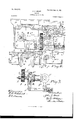
- Figure 1 is a side elevation of a turret-lathe embodying my invention, a part of the table A being broken away to show some interior mechanism.
- Fig. 2 is an end view of said machine with portions broken away to show certain parts of the operating mechanism.
- Fig. 3 is a sectional view through the edge of the platen and table A, showing the clamping devices by which these parts are clamped together.
- Fig. 4t is a plan view of that part of the supportingtable on which the platen rests.
- Fig. 5 is a plan view of the platen.
- Fig. 6 is an enlarged side view with the carriage, platen, and transverse shafts in vertical section, intended to show the mechanism for feeding the carriage and slide; and
- Fig. ⁇ 7 is a plan view of the clutch R and its operating mechanism.
- the lathe shown is a turret-lathe; but the omission of the turret and the substitution of some other tool-holding device would not involve any change in the parts of the machine which embody my invention.
- A represents the table or top of the machine-frame, the same being, as shown, a bottomless boxlike casting of appropriate shape.
- the mechanism at the head-stock end of the machine does not include any of the features of improvement which constitute the invention which this patent seeks to cover, and such mechanism may be of any Well-known or suitable construction.
- a platen B rests upon the table A, to which it is pivotally connected by a vertical stud K. This platen may swing in a horizontal plane about the axis of this pivot.
- the mechanism shown for so swinging the platen consists of a screw H, which passes through a horizontal hole in a vertical stud h, which is rotatably mounted in a bracket d on the side of the ta ble of the machine, and this screw has a head 7L', by which it may be turned.
- the screw screws through the lower end of a stud h2, which is swiveled on a vertical axis to the platen and projects downward therefrom through a hole a in the table.
- the platen may be fastened in any position into which it may be moved bysuitable clamping devices, which, as shown, consist of bolts u, which pass down through the holes h in the platen and through curved slots d2 and the opening a in the table and screw into clamping-plates u', which engage with the lower surfaces of the table and platen B.
- a sliding carriage O is mounted on the platen B and is suitably guided thereon-as, for example, by the hori- Zontal dovetailed ways h.
- a cross-slide D is mounted on the carriage O, being suitably guided thereon-as, for example, by dovetailed ways c.
- Turret F may be of a suitable construction, and it is mounted so as to be capable of rotation on a vertical axis on this slide D.
- Power-feedin g mechanisms for the carriage O and slide D are provided, and these mechanisms are of such construction that they will be operative regardless of the position of the platen. power-feeding mechanisms, as shown., will now be described. f
- a shaft E is mounted in brackets a3, fixed rPhe precise construction of such.
- this shaft in a machine of this" ism is concerned is the driving-shaft.
- a shaft J is mounted in the IOO spectively, both of which mesh with a bevelupward from the platen, which screw screws through a sleeve-nut' c', forming a part of a bracket c2, fastened to the carriage. Motion is transmitted from the shaft J to this feedscrew by the intermeshing gears j' and a clutch g' on the feed-screw.
- the gear j is attached to shaft J, the gear gis rotatably mounted on the screw G, and the gear jz is suitably mounted in bearings fixed to the platen.
- the gear g may be connected at will to the screw G.
- the movable member g of the clutch has a circumferential groove, into which projects two pins g3, which are attached to arms g4, said arms being rigid with the rock-shaft g5.
- This rock-shaft has au arm g, which is connected with au operating sliding red g', supported in brackets on the side of the platen and by which the clutch may be operated by hand.
- a collar g8 is adjustably secured to this rod in a position to be engaged by a iinger c6 on the carriage, whereby this rod may be moved and the clucth thrown out whenever the carriage has moved forward as far as desired.
- One of the arms g4 has a finger which projects up into the path of the carriage, and when the carriage has moved rearward far enough it will strike this iinger and throw out the clutch.
- the machine therefore acts automatically to throw out the clutch when the carriage has been fed forward or backward as far as desired.
- This feed-screw G may be turned by hand, if desired, when the clutch is thrown out through the following mechanisms, viz: the shaft I, which is mounted on the carria ⁇ ge,van operating-wheel t', secured to its outer end, the bevel-gears t,
- a bevel-gearm meshing with the bevel-gear t" and secured on a shaft M, which is mounted in a bracket c4 on the under side of the carriage C, a pinion m', which pinion is also secured to shaft M, and a pinion Q9, connected with the feed-screw by a tongue-and-groove connection.
- This pinion gg lies between the end of the sleeve-nut c and an arm c5, secured to the bracket c4, whereby as the carriage is moved this piston g9 will be moved upon the feed-screw, and thus maintains its operative relation with the pinion m.
- the turret-slide D is also moved by a feed-screw, l(indicated by N, which is mounted in the front end of the carriage C and screws through a bracket d2, fixed to the slide.
- This feed-screw has a gear rz,- fast to it, which gear meshes with a gear p, fast to, Va shaft P.
- This shaft P has at its outer end a hand-wheel p', by which it may be turned to feed the slide by hand.
- Loosely mounted on the shaft P is a bevel-gear p2, and a clutch R is provided for connecting this bevel-gear and shaft at will.
- the bevel-gear p2 meshes with the bevel-geartI on the upper end of the vertical shaft T, which is mounted in the bracket c2.
- a bevel-gear t is secured, and it meshes with a bevel-gearj3 on the feed-shaft J.
- This gear is connected to said shaft J bya tongue and groove, and the hub j4 of this gear has a circumfe rential groove which is embraced by an arm c7.
- This arm is a part of the bracket C2, and consequently the operative connection between the shafts P and J is maintained in all positions of carriage C.
- I claiu1- 1 The combination of a table, a platen supported thereon and connected thereto by a vertical pivot, a sliding carriage mounted on said platen, a carriage-feeding mechanism supported on the platen, a driving-shaft supported by the table, and mechanism which includes a rotatable member mounted axially with respect to said platen, intermediate of said driving-shaft and carriage-feeding mechanism, substantially as specified.
Landscapes
- Engineering & Computer Science (AREA)
- Mechanical Engineering (AREA)
- Machine Tool Units (AREA)
Description
Patented Oct. I5, 490W.
J. J. GRANT.
LATHE,
(Application led Jan. 14, 1901.
4 Sheets-Sheet I.
(No Model.)
N. my fs. ...my
.IN2/Witch M/Lne ses,
*me Nonms Enns cc. whom-mwa mmmamn. u. c.
Patented Oct. l5, 190|.
J. J. GRANT.
L A T H E (Application led Jan. 14, 1901.)
4 Shees-Sheei 2.
(No Model.)
vzz/ento;
Patented Oct. l5, IQUI. J. J. GRANT. A
LATHE.
{Application Bled Jan. 14, 1901.)
(No Model.)
,171 vento Nn. 684,635. Patented ont. 15, 190|. .1. LGRANT.
LATHE.
(Application filed Jan. 14, 1901.) (No Model.) 4 Sheets-Sheet 4.
UNITED STATES JOHN J. GRANT, OF CLEVELAND, OHIO.
LATHE.
SPECIFECATION forming part of Letters Patent No. 684,635, dated October l5, 1901.
Application filed January 14, 1901. Serial No. 43,186. (No model.)
T0 LZZ wiz/0711, t may concern;
Be it known that I, JOHN J. GRANT, a citizen of the United States, residing at Cleveland, in the county of Cuyahoga and State of Ohio, have invented a certain new and useful Improvementin Lathes, of which the following is a full, clear, and exact description, reference being had to the accompanying drawings.
The object of the invention is to provide a lathe of simple and novel construction having greater capacities for usefulness than machines of this character generally have.
The invention consists in the construction and combination of parts hereinafter described, and pointed out definitely in the claims.
In the drawings, Figure 1 is a side elevation of a turret-lathe embodying my invention, a part of the table A being broken away to show some interior mechanism. Fig. 2 is an end view of said machine with portions broken away to show certain parts of the operating mechanism. Fig. 3 is a sectional view through the edge of the platen and table A, showing the clamping devices by which these parts are clamped together. Fig. 4t is a plan view of that part of the supportingtable on which the platen rests. Fig. 5 is a plan view of the platen.- Fig. 6 is an enlarged side view with the carriage, platen, and transverse shafts in vertical section, intended to show the mechanism for feeding the carriage and slide; and Fig.^7 is a plan view of the clutch R and its operating mechanism.
The lathe shown is a turret-lathe; but the omission of the turret and the substitution of some other tool-holding device would not involve any change in the parts of the machine which embody my invention.
Referring to the parts by letters, A represents the table or top of the machine-frame, the same being, as shown, a bottomless boxlike casting of appropriate shape. The mechanism at the head-stock end of the machine does not include any of the features of improvement which constitute the invention which this patent seeks to cover, and such mechanism may be of any Well-known or suitable construction. A platen B rests upon the table A, to which it is pivotally connected by a vertical stud K. This platen may swing in a horizontal plane about the axis of this pivot.
This will throw the tool out ot' the axial line of the live-spindle, whereby tapered holes may be bored or nished. The mechanism shown for so swinging the platen consists of a screw H, which passes through a horizontal hole in a vertical stud h, which is rotatably mounted in a bracket d on the side of the ta ble of the machine, and this screw has a head 7L', by which it may be turned. The screw screws through the lower end of a stud h2, which is swiveled on a vertical axis to the platen and projects downward therefrom through a hole a in the table. The platen may be fastened in any position into which it may be moved bysuitable clamping devices, which, as shown, consist of bolts u, which pass down through the holes h in the platen and through curved slots d2 and the opening a in the table and screw into clamping-plates u', which engage with the lower surfaces of the table and platen B. A sliding carriage O is mounted on the platen B and is suitably guided thereon-as, for example, by the hori- Zontal dovetailed ways h. A cross-slide D is mounted on the carriage O, being suitably guided thereon-as, for example, by dovetailed ways c. Turret F may be of a suitable construction, and it is mounted so as to be capable of rotation on a vertical axis on this slide D.
Power-feedin g mechanisms for the carriage O and slide D are provided, and these mechanisms are of such construction that they will be operative regardless of the position of the platen. power-feeding mechanisms, as shown., will now be described. f
A shaft E is mounted in brackets a3, fixed rPhe precise construction of such.
to the frame beneath the table-top, and this 1 shaft in so far as the power-feeding mechan-v" As'a 'i matter of fact, this shaft in a machine of this" ism is concerned is the driving-shaft.
character will generally be driven from another shaft which drives other mechanisms; but, as before stated, this shaftE may be regarded as the driving-shaft of the powerfeeding devices. A shaft J is mounted in the IOO spectively, both of which mesh with a bevelupward from the platen, which screw screws through a sleeve-nut' c', forming a part of a bracket c2, fastened to the carriage. Motion is transmitted from the shaft J to this feedscrew by the intermeshing gears j' and a clutch g' on the feed-screw. The gear j is attached to shaft J, the gear gis rotatably mounted on the screw G, and the gear jz is suitably mounted in bearings fixed to the platen. By means of the clutch, which may be of any suitable con-struction, the gear g may be connected at will to the screw G. The movable member g of the clutch has a circumferential groove, into which projects two pins g3, which are attached to arms g4, said arms being rigid with the rock-shaft g5. This rock-shaft has au arm g, which is connected with au operating sliding red g', supported in brackets on the side of the platen and by which the clutch may be operated by hand. A collar g8 is adjustably secured to this rod in a position to be engaged by a iinger c6 on the carriage, whereby this rod may be moved and the clucth thrown out whenever the carriage has moved forward as far as desired. One of the arms g4 has a finger which projects up into the path of the carriage, and when the carriage has moved rearward far enough it will strike this iinger and throw out the clutch. The machine therefore acts automatically to throw out the clutch when the carriage has been fed forward or backward as far as desired. This feed-screw G may be turned by hand, if desired, when the clutch is thrown out through the following mechanisms, viz: the shaft I, which is mounted on the carria`ge,van operating-wheel t', secured to its outer end, the bevel-gears t,
secured to its inner end, a bevel-gearm, meshing with the bevel-gear t" and secured on a shaft M, which is mounted in a bracket c4 on the under side of the carriage C, a pinion m', which pinion is also secured to shaft M, and a pinion Q9, connected with the feed-screw by a tongue-and-groove connection. This pinion gg; lies between the end of the sleeve-nut c and an arm c5, secured to the bracket c4, whereby as the carriage is moved this piston g9 will be moved upon the feed-screw, and thus maintains its operative relation with the pinion m. The turret-slide D is also moved by a feed-screw, l(indicated by N, which is mounted in the front end of the carriage C and screws through a bracket d2, fixed to the slide. This feed-screw has a gear rz,- fast to it, which gear meshes with a gear p, fast to, Va shaft P. This shaft P has at its outer end a hand-wheel p', by which it may be turned to feed the slide by hand. Loosely mounted on the shaft P is a bevel-gear p2, and a clutch R is provided for connecting this bevel-gear and shaft at will. The bevel-gear p2 meshes with the bevel-geartI on the upper end of the vertical shaft T, which is mounted in the bracket c2. On the lower end of this shaft a bevel-gear t is secured, and it meshes with a bevel-gearj3 on the feed-shaft J. This gear is connected to said shaft J bya tongue and groove, and the hub j4 of this gear has a circumfe rential groove which is embraced by an arm c7. This arm is a part of the bracket C2, and consequently the operative connection between the shafts P and J is maintained in all positions of carriage C.
'has reached one end of its desired range of movement, and thereby the clutch will be thrown out. The other trip-arm o9 will strike the lever on the opposite side of its pivot when the slide reaches the other end of its. permitted travel, and thereby the clutch will be thrown out.
Having described my invention, I claiu1- 1. The combination of a table, a platen supported thereon and connected thereto by a vertical pivot, a sliding carriage mounted on said platen, a carriage-feeding mechanism supported on the platen, a driving-shaft supported by the table, and mechanism which includes a rotatable member mounted axially with respect to said platen, intermediate of said driving-shaft and carriage-feeding mechanism, substantially as specified.
2. The combination of atable, aplaten supA ported thereon and connected thereto by a vertical pivot, a sliding carriage mounted on the platen, a feed screw mounted on the platen, a nut secured to the carriage, a driving-shaft mounted in bearings secured to the machine-frame, mechanism for turning said feed-screw, and mechanism, including a gear mounted to rotate about the axis of the platen, for transmitting motion from the drivingi shaft to the feed-screw-operatin g mechanism, substantially as specified.
3. The combination of a table, a platen supported thereon and connected thereto by a vertical pivot, a sliding carriage mounted on said platen, a feed-screw mounted in bearings on the platen, a nut fast to the carriage, a driving-shaft mounted in fixed bearings on the machine-frame and having a beveled gear' secured to it, a shaft :mounted in bearingssecu red to the platen and having a bevel-gear' ICO IIO
secured to it, a bevel-gear meshing with said bevel-gears and mounted to rotate about the same axis as that upon which the platen turns, and mechanism intermediate of the lastnamed shaft and said feed-screw, substantially as specified.
4. The colnbination of a table, a platen supported thereon and connected thereto by a vertical pivot, a sliding carriage mounted on said platen, a feed-screw mounted upon the platen, a nut secured to the carriage, a gear mounted upon the feed-screw, a clutch for connecting said screw and gear, a drivingshaft supported by the table, a shaft mounted in bearings supported by the platen, beveled gears secured respectively to these two shafts, and an intermeshing bevel-gear mounted to rotate about the axis of the platen, mechanism transmitting motion from the shaft supported by the platen to the gear mounted on the feed-screw, clutch-operating mechanism having projections which are extended into the path of the carriage whereby the clutch is thrown out when the carriage reaches either end of its movement, substantially as specified.
5. The combination of a table, a platen supported thereon and connected thereto by a vertical pivot, a carriage mounted on the platen, a cross-slide mounted on the carriage, a feed-screw mounted on the carriage, a threaded bracket secured to the slide, a shaft mounted on the platen, a beveled gear embracing this shaft and connected thereto,- by a tongue-and-groove connection, means attached to the carriage for moving said gear along said shaft concurrently with the movement of the carriage upon the platen, and mechanism supported by the carriage for transmitting motion from said gear to the cross-slide feed-screw, substantially as specied.
6. The combination of a table, a platen supported thereon and connected thereto by a vertical pivot, a sliding carriage mounted on the platen, and a cross-slide mounted on said carriage, with a feed-screw mounted on the carriage, a threaded bracket secured to the slide, a vertical shaft supported by the carriage, mechanism intermediate of it and the feed-screw, a beveled gear secured to said vertical shaft, a shaft mounted on the platen, means for rotating it, a bevel-gear on said shaft and connected thereto by a tongue and groove, and means secured to the carriage for moving the gear along said feed-screw, substantially as specified.
7. The combination of a table, a platen supported thereon and connected thereto by a vertical pivot, a sliding carriage mounted on the platen, and a cross-slide mounted on said carriage, with a feed-screw mounted on the carriage, a threaded bracket secured to the slide, a vertical shaft supported by the carriage, mechanism intermediate of it and the feed-screw, a beveled gear secured to said vertical shaft, a shaft mounted on the platen,- means for rotating it, a bevel-gear on said shaft and connected thereto by a tongue and groove, and having a circumferential groove in its hub, and an arm secured to the carriage embracing said circumferential groove, substantially as specified.
In testimony whereof I hereunto affix myV signature in the presence of two witnesses.
JOHN J. GRANT.
Witnesses:
ALBERT H. BATES, E. B. GILcHRIsT.
Priority Applications (1)
| Application Number | Priority Date | Filing Date | Title |
|---|---|---|---|
| US4318601A US684635A (en) | 1901-01-14 | 1901-01-14 | Lathe. |
Applications Claiming Priority (1)
| Application Number | Priority Date | Filing Date | Title |
|---|---|---|---|
| US4318601A US684635A (en) | 1901-01-14 | 1901-01-14 | Lathe. |
Publications (1)
| Publication Number | Publication Date |
|---|---|
| US684635A true US684635A (en) | 1901-10-15 |
Family
ID=2753178
Family Applications (1)
| Application Number | Title | Priority Date | Filing Date |
|---|---|---|---|
| US4318601A Expired - Lifetime US684635A (en) | 1901-01-14 | 1901-01-14 | Lathe. |
Country Status (1)
| Country | Link |
|---|---|
| US (1) | US684635A (en) |
-
1901
- 1901-01-14 US US4318601A patent/US684635A/en not_active Expired - Lifetime
Similar Documents
| Publication | Publication Date | Title |
|---|---|---|
| US684635A (en) | Lathe. | |
| US554422A (en) | Milling machine | |
| US1338742A (en) | Lathe | |
| US1262235A (en) | Automatic feed-starter for drill-presses. | |
| US1057005A (en) | Portable electrically-operated tool. | |
| US610981A (en) | Lathe | |
| US1295583A (en) | Feeding mechanism. | |
| US2365078A (en) | Rotary table attachment for milling machines | |
| US703660A (en) | Boring-machine. | |
| US1124262A (en) | Lathe. | |
| US525863A (en) | Metal-turning lathe | |
| US972297A (en) | Universal lathe. | |
| US1137716A (en) | Clutch-shifting mechanism. | |
| US734051A (en) | Boring-machine. | |
| US513683A (en) | Milling machine | |
| US2211309A (en) | Power operated swivel carriage for hobbing machines | |
| US934105A (en) | Gearing. | |
| US776501A (en) | Slotting-machine. | |
| US480347A (en) | Slide feed mechanism | |
| US815697A (en) | Machine for drilling, boring, milling, &c. | |
| US275604A (en) | debozjtteyille | |
| US1098038A (en) | Cam-cutting mechanism. | |
| US597303A (en) | Pkqto-un | |
| US615146A (en) | Lathe | |
| US597390A (en) | Island |