US683203A - Sighting device for guns. - Google Patents
Sighting device for guns. Download PDFInfo
- Publication number
- US683203A US683203A US4115200A US1900041152A US683203A US 683203 A US683203 A US 683203A US 4115200 A US4115200 A US 4115200A US 1900041152 A US1900041152 A US 1900041152A US 683203 A US683203 A US 683203A
- Authority
- US
- United States
- Prior art keywords
- parallel
- sight
- glass
- tube
- diaphragm
- Prior art date
- Legal status (The legal status is an assumption and is not a legal conclusion. Google has not performed a legal analysis and makes no representation as to the accuracy of the status listed.)
- Expired - Lifetime
Links
- 239000011521 glass Substances 0.000 description 70
- 238000010276 construction Methods 0.000 description 10
- 238000009877 rendering Methods 0.000 description 9
- 229910052709 silver Inorganic materials 0.000 description 6
- 239000004332 silver Substances 0.000 description 6
- 239000012780 transparent material Substances 0.000 description 6
- 239000011248 coating agent Substances 0.000 description 4
- 238000000576 coating method Methods 0.000 description 4
- 239000000463 material Substances 0.000 description 4
- 230000007935 neutral effect Effects 0.000 description 4
- 230000003287 optical effect Effects 0.000 description 4
- 230000000052 comparative effect Effects 0.000 description 2
- 239000005331 crown glasses (windows) Substances 0.000 description 2
- 229910052751 metal Inorganic materials 0.000 description 2
- 239000002184 metal Substances 0.000 description 2
- 244000283070 Abies balsamea Species 0.000 description 1
- 235000007173 Abies balsamea Nutrition 0.000 description 1
- 241000385321 Brillia Species 0.000 description 1
- 239000004858 Canada balsam Substances 0.000 description 1
- 241001446467 Mama Species 0.000 description 1
- 208000027418 Wounds and injury Diseases 0.000 description 1
- 239000000853 adhesive Substances 0.000 description 1
- 230000001070 adhesive effect Effects 0.000 description 1
- 230000006378 damage Effects 0.000 description 1
- 239000000428 dust Substances 0.000 description 1
- 239000005308 flint glass Substances 0.000 description 1
- 238000005286 illumination Methods 0.000 description 1
- 208000014674 injury Diseases 0.000 description 1
- 238000012986 modification Methods 0.000 description 1
- 230000004048 modification Effects 0.000 description 1
- VYQNWZOUAUKGHI-UHFFFAOYSA-N monobenzone Chemical compound C1=CC(O)=CC=C1OCC1=CC=CC=C1 VYQNWZOUAUKGHI-UHFFFAOYSA-N 0.000 description 1
- 239000011022 opal Substances 0.000 description 1
- 239000003973 paint Substances 0.000 description 1
- 239000000126 substance Substances 0.000 description 1
Images


Classifications
-
- G—PHYSICS
- G02—OPTICS
- G02B—OPTICAL ELEMENTS, SYSTEMS OR APPARATUS
- G02B23/00—Telescopes, e.g. binoculars; Periscopes; Instruments for viewing the inside of hollow bodies; Viewfinders; Optical aiming or sighting devices
- G02B23/02—Telescopes, e.g. binoculars; Periscopes; Instruments for viewing the inside of hollow bodies; Viewfinders; Optical aiming or sighting devices involving prisms or mirrors
- G02B23/10—Telescopes, e.g. binoculars; Periscopes; Instruments for viewing the inside of hollow bodies; Viewfinders; Optical aiming or sighting devices involving prisms or mirrors reflecting into the field of view additional indications, e.g. from collimator
Definitions
- This invention has reference to a simple construction of sighting devices for use with small-arms, guns, and ordnance (all hereinafter included in the term guns. Where not inconsistent with the context) whereby a distant object can be sighted in an easier manner and with less skill than with the sights heretofore usually employed.
- a sighting device for this purpose according to this invention is so constructed that the distant object to be sighted or an image thereof and an im- .age of an object carried by the sighting de vice and constituting the sight proper can be superposed or'baused to coincide in such a way that they can be seen simultaneously and that the said image or sight proper shall appear to be approximately as far distant as the object being sighted, so that it can be viewed under practically the samebptical conditions as the distant object.
- such a sighting device comprises one or more pieces of parallel glass or equivalent material inclined to the line of sight and through which the object to be sighted can be seen and means whereby there can be partially reflected from the two surfaces of the piece of parallel glass or of each piece of parallel glass an im age of a sight, the rays of light from which are rendered parallel by being passed through alens of convex power before they reach the reflecting-sur l faces of the piece or pieces of parallel glass,
- the arrangement being such that the object and image can be seen simultaneously and that the image will appear to Abe as far distant as the object and will be viewed under practically the same optical conditions as the object, so that upon moving the gun to which the sighting device is applied sufficiently to canse the object and image to coincide the gun will be correctly sighted for the said object.
- the parallel glass is replaced by two right-angled prisms arranged with their adjacent inclined surfaces 1 near or close together and at an angle to the line of sight, while the vertical surfaces of the prisms are at right angles to the line of sight.
- the object and image are seen simultaneously and under the same optical conditions as before but theobject is seen by reflection and the image directly.
- the luminous rays from the sight are rendered parallel by reection from a concave retiector instead of by refraction through an object-glass. In each case the coincidence of the object and image is not adected by the position of the eye of the observer, so that it is not necessary to keep the eye stationary or even near to the sighting device.
- Sighting devices of the kind described can be constructed in various forms and applied to guns in various ways.
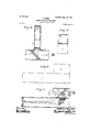
- Figure l is a side elevation
- Fig. 2 an end View
- Fig. 3 a longitudinal section on the line A A of Fig. 2
- Fig. 4 a plan, showing one construction of sighting device according to thisvinvention.
- Fig. 5 is asimilar view to Fig. 3, showing a modification.
- Figs. 6, 7, and 8 are similar views to Figs..l, 2,- ⁇ and 3, respectively, showing a modified construction of the sighting device.
- p Figs. 9 to 14, inclusive are similar views'to Fig. S, show- ⁇ ing further modied constructions of the sighting device.
- Figs. 15 to 33, inclusive show how sighting devices according to this invention can be applied to guns of various kinds.
- Figs. 15, 16, and 17 are respectively side, end, and plan views showing a magnifying-eyepiece combined with the sighting device.
- Figs. 18 and 19 are side and plan views, respectively; and
- Fig. 20 is a detail view showing an ordinary telescope combined with the sighting device.
- a is an inclined piece of parallel glass arranged within a holder b in the form of a tube, (hereinafter called the sighting-tube,) that is adapted to be suitably mounted on a gun, the piece of parallel glass being tixed Within the sighting-tube at an angle of fortyfive degrees to the longitudinal axis thereof which corresponds to the line of sight as.
- the sighting-tube Fixed at right angles to the sighting-,tube is IOO a second tube c, that is provided at its outer single image.
- the object will be seen or upper end with an opaqe diaphragm d, formed with a transparent design e, Fig. 4, through which light can pass and a ghost or phantom image of which is to be reiected in a backward direction fromv the inclined piece of parallel glass.
- the diaphragm d may conveniently be of glass covered with some opaque material-for example, a coating of silver or other metal or paint-through which a design e is cut, so as to appear as a bright design upon a black ground when viewed by transmitted light.
- the design e consists of two fine transparent lines arranged at right .angles to each other, so as to form a transparent cross.
- the design may, however, be of any other shape--for example, a circle.
- the collimatingtube At the inner end of the tube c (hereinafter called the collimatingtube) and near its junction with the sighting-tube b is an achromatic lens f, of convex power, (hereinafter called the object-glass,) which gives the necessary parallelism to the rays of light coming from the diaphragm d before they reach' the reflecting-surfaces of the in-.
- the position of the object-glass f should be such that its principal focus will be in the same plane as the diaphragm d.
- the outer end of the collimating-tube c must be soarranged that when the sighting device is in use the diaphragm d, with transparent design e, will be illuminated by naturalor artificial light.
- the reflecting power of one of its surfaces may be suitably increased-as, for example, by coating it with a lm of metal (for example, silver) or of suliid of lead, which, however, must be so thin as not to seriously interfere with the transparency of the glass.
- metal for example, silver
- suliid of lead which, however, must be so thin as not to seriously interfere with the transparency of the glass.
- the collimating-tube c is placed below the sighting-tube b and parallel to it, the light being bent by means of an inclined reflectingsurface before it passes'through the object- ⁇ of sighting device shown in Figs. 6, 7, and 8 glass f and reaches the parallel glass a.
- the reflecting-surface is formed by the inclined back surface of a right-angled prism k of suitable glass, such as light fiintglass. 'Ihe right-angled prism k may have -plane surfaces and be used in conjunction with an object-glass f, as shown in Figs. 8.
- object-glass and pr'sm may be combined in the form of what is ugually called an object-glass prism, as shown in Figs. 10 and 11. -As hereinbefore mentioned, a
- piece of neutral tint-glass h may be placed in front ofthe sighting-tube b, either attached rigidly thereto or, as shown in Fig. 11, mounted in a hinged frame l, as under some conditions better results will be obtained without its use and under other conditions of illumination with its use.
- phragm d a hinged metallic cap or shutter m
- Fig. 11 which when closed against the said tube c serves to protect the diaphragm d from injury and from dust or rain.
- This shutter 'm may be provided on its innerside with a reflector fn., of silvered plate or other suitable reflecting material, which when Ythe shutter is partly open serves to reflect the light 'of the sky into the collimating-tube c and to illumi s nate the design on the diaphragm d.
- shutter m is best left completely open, so as to utilize the light coming through the casemate or port-hole; but under other circumstances, such 4as with a field-gun, it will be found more advantageous to use the shutter half-way open, so as to reflect the skylight into the collimating-tube c through the diaphragm 12 a sighting-tube is dispensed with in order that there may be, nothing to obstruct the field of view around the plate or plates of parallel glass.
- the collimating-tube c is made as before, with its diaphragm d and ob ject-glass f complete in itself, and the reflecting arrangement is made in the form of a single piece of very thick glass a, having parallel surfaces and inclined at an angle of fortyfive degrees to the axis of the collimatingtube.
- parallel rays of light coming from the object-glass f will pass first into the lower Yhalf of the piece of glass' a and reach the back surface thereof, which at the part marked with the thick line s is 'silvered, so that the rays will be almost totally reflected thereform.
- a piece of very light neutral tinted glass h may be arranged near to but not in optical contact with the said surface s', as shown in dotted lines in Fig. 12.
- the parallel glass is replaced by two' right-angled prisms u and o, of crown-glass, arranged as shown,so that theiradjacent inclined surfaces w are near together, but not in actual contact with each other,and are inclined at an angle of about fifty degrees to the line of sight :awhile their vertical surfaces y are at right angles to the line of sight.
- the two prisms may be held together by an interposed layer of suitable adhesive material placed between them near to their'outer sides only.
- the object-glassprism 7c is shown as made in one piece with the adjacentprism u; butit maybe made separate from such prism u, if desired.
- the glass prism k which will then be of crownglass, should be silvered on its inclined rear surface to render the same ⁇ refiecting.
- V the vertical surfaces
- the prism fu a second inclined reflecting-surface w is obtained IOO which will nearly double the brilliancy of the phantom image produced.
- the prisms u and e.) will allow of the greater portion of thelight fromadistant object passing through them, only a small amount of such light being reflected from the inclined surfaces w.
- the right-angled prisms u and o may be made with angles of forty-five degrees, so that the said surfacesw will be inclined at forty-five degrees tothe line of sight if the said two surfaces be cemented together, as by Canada balsam, and one of them be previously coated with a semitransparent film for coating of a reflecting substance, such as silver.
- a prism 7s' preferably of light flint-glass, is arranged in the tube b and the inclined piece of parallel glass a is arranged below it in the tube @and behind the object-glass f.
- One of the surfaces of the piece of parallel glass a is preferably coated with a film of silver of IIO such a thickness as to be not quite opaque,
- Fig. leta shows one construction for this purvarnish or paint, to, form a diaphragm
- This sight is illuminated from behind by light that passes through the opening d* and falls upon and is reflected from the inclined rear surface d3 of the prism, the di-4 verging luminous rays from the sight impnging upon the rear concave surface of the reflector, from which they are refiected backward as parallel rays.
- the arrangement is such that a distant object can be seen directly through the conca ⁇ 'e reliector and the image of the sight can be superposed on it and the two viewed together, as in the other arrangements of sighting device hereinbefore described.
- ktheinner concave surface of the reflector a.' may be coated with a semitransparent film of a reflecting medium, such as silver or sullid of lead, like some of the plane reflectors hereinbefore described.
- opening d* may be glazed with opal or groundor clear glass and may in the latter case have a mirror mounted over it to direct light therethrough.
- Sighting devices can be used by the unaded eye or in connection with a telescope, field-glass, or equivalent device for more distinctly observing the object to be sighted.
- a telescope, field-glass, or equivalent device for more distinctly observing the object to be sighted.
- a Iield -glass or other form of telescope can be used to view the superimposed images of object and phantom sight which will simultaneously be in focus.
- sighting devices may be 'ceases constructed in forms other than those here-l inabove indicated as examples. ⁇
- a sighting device of the kind described can be mounted upon a gun in any suitable or known way to allow for angular movement in vertical and horizontal planes to suit variations 'in range, wind-pressure, and the other variable conditions to which such devices must comply.
- Figs. 15, 16, and 17 show'how an eyepiece of well known construction having two pairs cf reflecting-prisms and an object-glass and designed to magnify theimage of the sight and the View of a distant object can be applied to the sighting device in such away that it can be brought into position to facilitate the observation of the image of the sight and a distant object or can be moved out of position, as may be desired.
- the carrier 20, in which the sighting device b c may be held is provided with a bearing 30, in which the said eyepiece 3l is mounted to' turn about a horizontal axis, so that it can at will be turned either into the operative position shown in'full lines in Figs. 15, 16, and 17 or into the inoperative position shown in dotted lines in Figs. 16 aud 17.
- Figs. 18, 19, and 2O show how an ordinary telescope 29 can be used in connection with the sighting device b c for sighting objects at a great distance.
- the rear end of the sight-carrier 20 is formed with a pair of vertical guides 32, Fig. 20, to receive and hold the rim 33 on the forward end ofl the telescope and with a backwardly-projecting extension 34 to serve as a rest for the body of the telescope, as shown in Fig. 18.
- a sighting device for guns comprising a sight and means whereby luminous rays proceeding therefrom to the eye of an observer are rendered parallel to one another.
- a sighting device for guns comprisinga sight and means whereby luminous rays proceeding therefrom can be rendered parallel to one another and there is produced an image thatcan be superposed upon and viewed simultaneously with a distant object.
- a sighting device for guns comprising a sight, means for rendering luminous rays proceeding therefrom parallel to one another, and a surface from which an image of the sight produced by the parallel luminous rays can IOO IIO
- a sighting device for guns com prisin g a sight, means for rendering luminous rays proceeding therefrom parallel. to one another, and reflecting-surfaces whereby views of the sight and a distant object can be superposed and viewed simultaneously.
- a sighting device for guns comprising a sight, ⁇ means whereby luminous rays proceeding therefrom can be rendered parallel be" fore reaching the eye of an observer, and
- a sighting device for guns comprising a sight, means whereby luminous rays proceeding therefrom are rendered parallel, and one or more inclined surfaces through which a distant object can be viewed and from which an image of the sight produced by the parallel rays will be reflected in a backward direction.
- a sighting device for guns comprising a sight, means whereby luminous rays proceeding therefrom are rendered parallel, one or more pieces of transparent material having parallel surfaces inclined to the line of sight through said device, through which a distant object can be seen, and by which an image of the sight will be reflected in a backward direction.
- a sighting device forguns comprising a tube, a diaphragm carried by 'said tube and bearing a design constituting the sight proper, means whereby luminous rays proceeding from said design or sight are rendered parallel, and a transparent body1 through which a distant object can be seen and having one or more inclined surfaces upon which the parallel luminous rays are projected so as to produce an image of said design or sight.
- a sighting device forguns comprising a tube provided with a diaphragm bearing a design constituting the sight proper, atransparent body having one or more inclined reflecting-surfaces external to said tube and through which a distantv object can be seen,
- an object-glass arranged to render lumi-l notebook rays proceeding from said diaphragm parallel to one another and to direct said parallel rays onto said inclined reflecting surface or surfaces.
- a sighting device for guns com prising a tube provided with a diaphragm bearing a design constituting thc sight proper, means for directing light upon said diaphragm, an object-glass capable of rendering luminous rays proceedingfrom said diaphragm parallel to one another, and an inclined surface from 'which parallel rays both from the illuminated design and from a distant objectcan be caused to simultaneously enter the eye of an observer.
- a tube provided with a diaphragm bearing a transparent design to constitute the sight proper, an object-glass arranged to render luminous rays proceeding from said design parallel to one another, and an inclined surface from which an image of the design produced by the parallel rays'will be reflected and through which a distant object can be simultaneously viewed.
- Asightiug device forguns comprising a tube provided with a diaphrain bearing a transparent design to constitute the sight proper, a reflecting-surface external'to said tube, inclined in a backward direction to the line of sight through said device, and through which a distant object can be viewed, a reflecting -surface wit-hin said tube whereby luminous rays proceeding from said design are reflected onto the external reflecting-surface and thence backward, and means arranged to render said rays parallel to one another before they reach the external refleeting-surface.
- Asighting device forguns comprising a tube provided with a diaphragm bearing a design constituting the sight proper, a transparent body external to said tube and inclined backward to the axis thereof, a rightangled prism having its inclined surface ar- 'ranged to reflect luminous rays proceeding from said design onto the external reflectingsurface, and anobject-glass arranged to render said rays parallel to one another before reaching the last-mentioned surface.
- Asightingdevice for guns comprising a tube provided with a diaphragm bearinga design constituting the sight proper, pieces of transparent parallel glass arranged external to said tube and inclined backward to 'the axis of said tubeya right-angled prism arranged within said tube so as to reflect 1uminous rays coming from said diaphragm onto the inclined surfaces of the parallel glass, and an object-glass arranged between said prism and piecesv of parallel glass so as to render the luminous'rays parallel to one another.
- Asightingdevice forguns comprising a tube having a diaphragm carrying the sight proper, a transparent body external to said tube and having one or more backwardly-inclined reflecting-surfaces, means for rendering luminous rays proceeding from said diaphragm and sight parallel t0 one another and directing them onto said inclined reflecting surface or surfaces, and transparent material adapted to be placed adjacent to said transparentbody and to diminish the brilliancy of a distant object as seen through said transparent body.
- Asightingdeviceforguns comprisinga tube having a diaphragm carrying the sight proper, a transparent body external to said ltube and having one or more backwardly-inclined refiectingfsurfaces, means for rendering luminous rays proceeding from said diaphragmand sight parallel to one another and directinggjthem onto said inclined reliecting surface-orsurfaces', and -an incandescent electric lamp arranged to illuminate said diaphragm and sightf-j f 22.
- Asightingde-v' eforguns comprising a sighting-tube having-fone or more pieces of parallel transparent glass arranged across the axis thereof and 'inclined backwardV to said axis, a collimating-tubehaving 'a diaphragm provided with a transparentvtdesign, and means whereby luminous rays from said-diaphragm are rendered parallel and directed onto the inclined surfaces of said transparent material.
- Asightingdeviceforguns comprising a sighting-tube having one or more pieces of parallel glass extending across the same and inclined backward to the axis of said tube, a collimating-tube arranged' parallel to said sighting-tube and provided with a diaphragm bearin g a transparent design constituting the sight proper, aright-angled prism arranged in said collimating-tube so as to reflect 1uminous rays coming from said sight onto the inclined surfaces of the parallel glass, and
- a sighting device for guns comprisinga sighting-tube having one or more pieces of.
- a collimating-tube having a diaphragm provided with a transparent design, means whereby luminous rays from said diaphragm are rendered' parallel and directed onto the inclined surfaces of said transparent material, and transparent material adapted to be placed in front of said parallel glass and diminish the brilliancy of a distant obamount of external lightcan be directed upon said diaphragm.
Landscapes
- Physics & Mathematics (AREA)
- Astronomy & Astrophysics (AREA)
- General Physics & Mathematics (AREA)
- Optics & Photonics (AREA)
- Telescopes (AREA)
Description
No. 683,203. Patented sept. 24, |901.
H. Gauss.
SIGHTING DEVICE FR GUNS.
(Application 'led Dec. 26, 1900.)
(No Mudd.) 6 Shees-Sheet l,
IA 223x 4 l /MCSVUCHLOP N0. 683,203. Patentad Sept. 24, |90|` H. Gnu. smunm; navlce Fon Guns.
. (Application tiled Dec. 26, 1900.) (No Model.) 6 Sheets-Sheet 2.
Patented Sept. 24, I90I. H. GRUBB. SIGHTING DEVICE FOR GUNS.
(Application led Dec. 26, 1900.)
6 Sheets-Sheetv 3.
(No Model.)
Patented sept. 24, |901.
H. GRUBB. SIGHTING nEvlcl-z Formuns.
(Application med Dec. 26, 1900.)
6 Sheets-Sheet 4.
(No ModeL) W Mehrweg H. GRUBB.
SIGHTING DEVICE FOR GUNS.
Patented Sept. 24, 190|.
(Application led Dec. 28, 1000..
6 Sheets-Sheet 5.
(No Model.)
@Ramses @f/w Q Patented sept. 24, mol. H. Gnu. SIGHTING DEVICE FOB GUNS.
' `(Application med Dec. 26, 1900.) (No Model.) 6 Sheets-Sheet 6.
l1 n. L c v +33 I; il!
@nl/enter* Mamas.
Y UNITED STATES PATENT rrlcn.
HOWARD GRUBB, OF DBLIN., IRELAND.
VslcHrlNc DEVICE FOR euNs.
SPECIFICATION forming part of Letters Patent No. 683,203, dated September 24, 1901.
Application filed December 26, 1900. Serial. No. 411152- (NO model-l v I u To alba/hom it -may concern:
Beit known that I,HOWARD GRUBB,K'night, a subject of the Queen of Great Britain and Ireland, residing at Dublin, Ireland, have invented Improvement-s in Sighting Devices for Guns, of which the following is a specification.
This invention has reference to a simple construction of sighting devices for use with small-arms, guns, and ordnance (all hereinafter included in the term guns. Where not inconsistent with the context) whereby a distant object can be sighted in an easier manner and with less skill than with the sights heretofore usually employed. A sighting device for this purpose according to this invention is so constructed that the distant object to be sighted or an image thereof and an im- .age of an object carried by the sighting de vice and constituting the sight proper can be superposed or'baused to coincide in such a way that they can be seen simultaneously and that the said image or sight proper shall appear to be approximately as far distant as the object being sighted, so that it can be viewed under practically the samebptical conditions as the distant object. According to one construction such a sighting device comprises one or more pieces of parallel glass or equivalent material inclined to the line of sight and through which the object to be sighted can be seen and means whereby there can be partially reflected from the two surfaces of the piece of parallel glass or of each piece of parallel glass an im age of a sight, the rays of light from which are rendered parallel by being passed through alens of convex power before they reach the reflecting-sur l faces of the piece or pieces of parallel glass,
the arrangement being such that the object and image can be seen simultaneously and that the image will appear to Abe as far distant as the object and will be viewed under practically the same optical conditions as the object, so that upon moving the gun to which the sighting device is applied sufficiently to canse the object and image to coincide the gun will be correctly sighted for the said object.
' Inra modified construction the parallel glass is replaced by two right-angled prisms arranged with their adjacent inclined surfaces 1 near or close together and at an angle to the line of sight, while the vertical surfaces of the prisms are at right angles to the line of sight. According to anotheigconstruction the object and image are seen simultaneously and under the same optical conditions as before but theobject is seen by reflection and the image directly. In another construction" the luminous rays from the sight are rendered parallel by reection from a concave retiector instead of by refraction through an object-glass. In each case the coincidence of the object and image is not adected by the position of the eye of the observer, so that it is not necessary to keep the eye stationary or even near to the sighting device.
Sighting devices of the kind described can be constructed in various forms and applied to guns in various ways.
In the accompanyingillustrative drawings, Figure l is a side elevation, Fig. 2 an end View, Fig. 3 a longitudinal section on the line A A of Fig. 2, and Fig. 4 a plan, showing one construction of sighting device according to thisvinvention. Fig. 5 is asimilar view to Fig. 3, showing a modification. Figs. 6, 7, and 8 are similar views to Figs..l, 2,-` and 3, respectively, showing a modified construction of the sighting device. p Figs. 9 to 14, inclusive, are similar views'to Fig. S, show-` ing further modied constructions of the sighting device. Figs. 15 to 33, inclusive, show how sighting devices according to this invention can be applied to guns of various kinds. Figs. 15, 16, and 17 are respectively side, end, and plan views showing a magnifying-eyepiece combined with the sighting device. Figs. 18 and 19 are side and plan views, respectively; and Fig. 20 is a detail view showing an ordinary telescope combined with the sighting device. i
, In the sighting device shown in Figs. 1,2, and 3, a is an inclined piece of parallel glass arranged within a holder b in the form of a tube, (hereinafter called the sighting-tube,) that is adapted to be suitably mounted on a gun, the piece of parallel glass being tixed Within the sighting-tube at an angle of fortyfive degrees to the longitudinal axis thereof which corresponds to the line of sight as. Fixed at right angles to the sighting-,tube is IOO a second tube c, that is provided at its outer single image.
lthe sighting-tube b the object will be seen or upper end with an opaqe diaphragm d, formed with a transparent design e, Fig. 4, through which light can pass and a ghost or phantom image of which is to be reiected in a backward direction fromv the inclined piece of parallel glass. The diaphragm d may conveniently be of glass covered with some opaque material-for example, a coating of silver or other metal or paint-through which a design e is cut, so as to appear as a bright design upon a black ground when viewed by transmitted light. In the example Fig. 4 the design e consists of two fine transparent lines arranged at right .angles to each other, so as to form a transparent cross. The design may, however, be of any other shape--for example, a circle. At the inner end of the tube c (hereinafter called the collimatingtube) and near its junction with the sighting-tube b is an achromatic lens f, of convex power, (hereinafter called the object-glass,) which gives the necessary parallelism to the rays of light coming from the diaphragm d before they reach' the reflecting-surfaces of the in-.
clined piece of parallel glass from which they are reflected to the eye of t-he observer. For this purpose the position of the object-glass fshould be such that its principal focus will be in the same plane as the diaphragm d. The outer end of the collimating-tube c must be soarranged that when the sighting device is in use the diaphragm d, with transparent design e, will be illuminated by naturalor artificial light. With the arrangement described when an observer looks through the sighting-tube b in the direction shown by the arrow g, Fig. 3, it is possible to see the object aimed at with practically the same amount of distinctness and brilliancy as if the piece of parallel glass a were not present, and by suitably adjusting the position of the sighting device the center of the phantom image of the cross e can be caused tocoincide inposition with the said object, the said image being partially re ected from' the two surf faces of Ithe piece ofl arallel glass, .and thus reflectedv into the eye simultaneously with a view of the object.l If the partsbe arranged as -described and shown, the rays of light en- .tering the eye after reflection from the parallel glass will be parallel rays, and therefore any object, such as the cross e, placed in the plane of the diaphragm will be seen under the same conditions as if it were a large object placed at a'great distance instead of what it really is-viz a small object placed at a small distance-aud if the two surfaces of the glass be perfectly parallel the two images as seen reflected from the two surfaces will be accurately superposed, so as to appear as a Therefore on looking through under practically the normal conditions of vision, and su perposed upon the object will be seen the ghost or phantom image of whatever device e has been formed on or-,in the diaphragm d, the brilliancy of this image depending upon the relative brilliancy of the skyoi other source of light used to illuminate the diaphragm as compared with the brillia'ncy of the object itself. In some cases it is difiicult with the arrangement above described to obtain a sucient brilliancy of the phantom image, the worst conditions probably being when the sky overhead` is of a deep-blue color,while the object aimed at is very bright. Under most circumstances, therefore, it will be advantageous to use several pieces of parallel glass arranged one immediately behind the other, as illustrated in Fig. 5, where three pieces a of parallel glass are used. In this way the brilliancy of the phantom image will be increased by reason of the fact that the'reflections from the whole six surfaces of the three pieces of parallel glass are superposed one upon another. For a like purpose when using a single piece of glass the reflecting power of one of its surfaces may be suitably increased-as, for example, by coating it with a lm of metal (for example, silver) or of suliid of lead, which, however, must be so thin as not to seriously interfere with the transparency of the glass. Also itis sometimes desirableto place a piece h of faintly-tinted neutral glass across the front end of the sighting-tube b, as shown in Fig. 11, whereby the brilliancy ofv the object aimed at is reduced and the comparative brilliancy of the phantom image increased.
In the simpler and more convenient form the collimating-tube c is placed below the sighting-tube b and parallel to it, the light being bent by means of an inclined reflectingsurface before it passes'through the object- `of sighting device shown in Figs. 6, 7, and 8 glass f and reaches the parallel glass a. In Y the example the reflecting-surface is formed by the inclined back surface of a right-angled prism k of suitable glass, such as light fiintglass. 'Ihe right-angled prism k may have -plane surfaces and be used in conjunction with an object-glass f, as shown in Figs. 8.
and 9, or the object-glass and pr'sm may be combined in the form of what is ugually called an object-glass prism, as shown in Figs. 10 and 11. -As hereinbefore mentioned, a
IIO
piece of neutral tint-glass h may be placed in front ofthe sighting-tube b, either attached rigidly thereto or, as shown in Fig. 11, mounted in a hinged frame l, as under some conditions better results will be obtained without its use and under other conditions of illumination with its use.
Also it is desirable in.
most cases to provide at the outer or forward.
end of the colli mating-tube c, outside the dia.-l
phragm d, a hinged metallic cap or shutter m,
Fig. 11, which when closed against the said tube c serves to protect the diaphragm d from injury and from dust or rain. This shutter 'm may be provided on its innerside with a reflector fn., of silvered plate or other suitable reflecting material, which when Ythe shutter is partly open serves to reflect the light 'of the sky into the collimating-tube c and to illumi s nate the design on the diaphragm d. When using the sighting device in a casemate-battery or between decks on a naval gun, the
shutter m is best left completely open, so as to utilize the light coming through the casemate or port-hole; but under other circumstances, such 4as with a field-gun, it will be found more advantageous to use the shutter half-way open, so as to reflect the skylight into the collimating-tube c through the diaphragm 12 a sighting-tube is dispensed with in order that there may be, nothing to obstruct the field of view around the plate or plates of parallel glass. In this case the collimating-tube c is made as before, with its diaphragm d and ob ject-glass f complete in itself, and the reflecting arrangement is made in the form of a single piece of very thick glass a, having parallel surfaces and inclined at an angle of fortyfive degrees to the axis of the collimatingtube. In this arrangement parallel rays of light coming from the object-glass f will pass first into the lower Yhalf of the piece of glass' a and reach the back surface thereof, which at the part marked with the thick line s is 'silvered, so that the rays will be almost totally reflected thereform. The rays then pass in the direction shown by the dotted lines to the upper part of the inclined front surface s' of the piece of glass, whence they are partially reflected backward into the eye of an observer. By using a thick piece of glass a, as shown, there will be little or no objection to leaving it quite unprotected, and it will enable a complete eld of view to he-obtainedthat is unobstructed by any opaque material above the collimating-tube. To obtain the best results with this arrangement of sighting device, the
diaphragmd shouldbe strongly illuminated, as there is only a single and therefore slight reflection of the rays of light from the inclined front surface s' of the piece of glass a. To increase the brilliancy of the phantom image reflected from the inclined surface s', a piece of very light neutral tinted glass h may be arranged near to but not in optical contact with the said surface s', as shown in dotted lines in Fig. 12. This would have the eect not only of reducing the brilliancy of the distant object seen directly through the piece of glass, and therefore increasing the comparative brilliancy of the phantom image, but would also enable the reflections from both surfaces of the piece of neutal tinted glass to be utilized to increase the brilliancy of the image, or the surface s'may have a very thin semitransparent metallic or other reflective coatingfor example, silver or sulfid of lead-deposited on it to increaseits refleeting power. If, however, the diaphragm d of the saidsighting device, Fig. 12, have combined with it anl electric lamp, the brilliancy of the phantom image will for many purposes be quite sufficient without using the piece of neutral tinted glass h or coating the surface s with a reflecting-film.
In the sighting device shownin Fig. 13 the parallel glass is replaced by two' right-angled prisms u and o, of crown-glass, arranged as shown,so that theiradjacent inclined surfaces w are near together, but not in actual contact with each other,and are inclined at an angle of about fifty degrees to the line of sight :awhile their vertical surfaces y are at right angles to the line of sight. The two prisms may be held together by an interposed layer of suitable adhesive material placed between them near to their'outer sides only. The object-glassprism 7c is shown as made in one piece with the adjacentprism u; butit maybe made separate from such prism u, if desired. In the former case the glass prism k, which will then be of crownglass, should be silvered on its inclined rear surface to render the same `refiecting. In this arrangement it will be seen that the parallel rays of light coming from the objectglass f enter and leave the vertical surfaces" V of the combined prisms k'and u, at right angles to such surfaces,sothat there will be little loss of such light in passing through the prisms, while by the use of the prism fu a second inclined reflecting-surface w is obtained IOO which will nearly double the brilliancy of the phantom image produced. The prisms u and e.) will allow of the greater portion of thelight fromadistant object passing through them, only a small amount of such light being reflected from the inclined surfaces w. Instead of arrangingthe inclined surfaces w at an angle of about fifty degrees to the line of sight the right-angled prisms u and o may be made with angles of forty-five degrees, so that the said surfacesw will be inclined at forty-five degrees tothe line of sight if the said two surfaces be cemented together, as by Canada balsam, and one of them be previously coated with a semitransparent film for coating of a reflecting substance, such as silver.
In the modified construction shown in Fig. 14 a prism 7s', preferably of light flint-glass, is arranged in the tube b and the inclined piece of parallel glass a is arranged below it in the tube @and behind the object-glass f. One of the surfaces of the piece of parallel glass a, is preferably coated with a film of silver of IIO such a thickness as to be not quite opaque,
so as to increase its reflecting power, while still leaving it suiiicientlytransparent toenable an image ofthe design on the diaphragm d to be seen by the parallel luminous rays' passing through it. Vith this arrangement ,the distant object will be seen by reflection from the inclined refiecting-surface of the prism lo' aud-the inclined reflecting-surface of the parallel glass a, while a direct image 'of the design on the diaphragm d will be produced by the parallel rays of light proceeding from the object-glassf, so that the said object and image can be seen simultaneously and the image will appear to be approximately as far distant as the object and can be viewed under the same optical conditions as such object, as in the other arrangements of sighting devices hereinbefore described.
Instead of rendering the luminous rays proceeding from the sight parallel by refraction through a convex lens-i. e., an object-glass, as in the arrangements hereinbefore 1described-they may be rendered parallel by relection from a concave refiecting-surface.
Fig. leta shows one construction for this purvarnish or paint, to, form a diaphragm,
through which a design such as a fine cross or circle is cut to constitute a sight, as bei fore. This sight is illuminated from behind by light that passes through the opening d* and falls upon and is reflected from the inclined rear surface d3 of the prism, the di-4 verging luminous rays from the sight impnging upon the rear concave surface of the reflector, from which they are refiected backward as parallel rays. The arrangement is such that a distant object can be seen directly through the conca\'e reliector and the image of the sight can be superposed on it and the two viewed together, as in the other arrangements of sighting device hereinbefore described. To increase the brilliancy of the image of the sight, ktheinner concave surface of the reflector a.' may be coated with a semitransparent film of a reflecting medium, such as silver or sullid of lead, like some of the plane reflectors hereinbefore described. The
opening d* may be glazed with opal or groundor clear glass and may in the latter case have a mirror mounted over it to direct light therethrough.
Sighting devices according to this invention can be used by the unaded eye or in connection with a telescope, field-glass, or equivalent device for more distinctly observing the object to be sighted. As the rays entering the eye from the object and from the phantom sight are practically parallel, a Iield -glass or other form of telescope can be used to view the superimposed images of object and phantom sight which will simultaneously be in focus. Also such sighting devices may be 'ceases constructed in forms other than those here-l inabove indicated as examples.`
A sighting device of the kind described can be mounted upon a gun in any suitable or known way to allow for angular movement in vertical and horizontal planes to suit variations 'in range, wind-pressure, and the other variable conditions to which such devices must comply.
Figs. 15, 16, and 17 show'how an eyepiece of well known construction having two pairs cf reflecting-prisms and an object-glass and designed to magnify theimage of the sight and the View of a distant object can be applied to the sighting device in such away that it can be brought into position to facilitate the observation of the image of the sight and a distant object or can be moved out of position, as may be desired. For this purpose the carrier 20, in which the sighting device b c may be held, is provided with a bearing 30, in which the said eyepiece 3l is mounted to' turn about a horizontal axis, so that it can at will be turned either into the operative position shown in'full lines in Figs. 15, 16, and 17 or into the inoperative position shown in dotted lines in Figs. 16 aud 17.
Figs. 18, 19, and 2O show how an ordinary telescope 29 can be used in connection with the sighting device b c for sighting objects at a great distance.` For this purpose the rear end of the sight-carrier 20 is formed with a pair of vertical guides 32, Fig. 20, to receive and hold the rim 33 on the forward end ofl the telescope and with a backwardly-projecting extension 34 to serve as a rest for the body of the telescope, as shown in Fig. 18.
What I claim is- 1. A sighting device for guns, comprising a sight and means whereby luminous rays proceeding therefrom to the eye of an observer are rendered parallel to one another.
2. A sighting device for guns, comprisinga sight and means whereby luminous rays proceeding therefrom can be rendered parallel to one another and there is produced an image thatcan be superposed upon and viewed simultaneously with a distant object.
3. A sighting device for guns, comprising a sight, means for rendering luminous rays proceeding therefrom parallel to one another, and a surface from which an image of the sight produced by the parallel luminous rays can IOO IIO
be reliected and caused to enter the eye of an observer simultaneouslywith a view of a distant object.
4. A sighting device for guns, com prisin g a sight, means for rendering luminous rays proceeding therefrom parallel. to one another, and reflecting-surfaces whereby views of the sight and a distant object can be superposed and viewed simultaneously.
5. A sighting device for guns, comprising a sight, `means whereby luminous rays proceeding therefrom can be rendered parallel be" fore reaching the eye of an observer, and
means whereby the brilliaucy of a distant ob- A sight, a lamp for illuminating said sight, and
means whereby luminous rays proceeding from said sight can be rendered parallel to one another.
'8. A sighting device for guns, comprising a sight, means whereby luminous rays proceeding therefrom are rendered parallel, and one or more inclined surfaces through which a distant object can be viewed and from which an image of the sight produced by the parallel rays will be reflected in a backward direction.
9. A sighting device for guns, comprisinga sight, means whereby luminous rays proceeding therefrom are rendered parallel, one or more pieces of transparent material having parallel surfaces inclined to the line of sight through said device, through which a distant object can be seen, and by which an image of the sight will be reflected in a backward direction.
10. Asightingd-evicefoi-guns,comprisiuga sight, an object-glass whereby luminous rays proceeding therefrom are rendered parallel, and one or more reflecting-surfaces arranged at an angle to the line of sight and upon which the parallel luminous rays are projected so as to produce a phantom image of said sight.
1l. A sighting device forguns, comprising a tube, a diaphragm carried by 'said tube and bearing a design constituting the sight proper, means whereby luminous rays proceeding from said design or sight are rendered parallel, and a transparent body1 through which a distant object can be seen and having one or more inclined surfaces upon which the parallel luminous rays are projected so as to produce an image of said design or sight.
l2. A sighting device forguns, comprising a tube provided with a diaphragm bearing a design constituting the sight proper, atransparent body having one or more inclined reflecting-surfaces external to said tube and through which a distantv object can be seen,
and an object-glass arranged to render lumi-l nous rays proceeding from said diaphragm parallel to one another and to direct said parallel rays onto said inclined reflecting surface or surfaces.
13.- Asightingdevicefoi-guns,comprisinga tube provided with a diaphragm bearing a? design constituting the sight proper, an' ob- Ject-glass capable of rendering luminous rays proceeding from said design parallel toone another, a transparent body through which a distant object can be viewed and from which an image of the design or sight, produced by the parallel luminous rays will be' reflected', and transparent material arranged in front of said transparent body and capable of reducing the brilliancy of said distant object as seen through said transparent body.
14.l A sighting device for guns,com prising a tube provided with a diaphragm bearing a design constituting thc sight proper, means for directing light upon said diaphragm, an object-glass capable of rendering luminous rays proceedingfrom said diaphragm parallel to one another, and an inclined surface from 'which parallel rays both from the illuminated design and from a distant objectcan be caused to simultaneously enter the eye of an observer.
15. In a sighting device for guns, a tube provided with a diaphragm bearing a transparent design to constitute the sight proper, an object-glass arranged to render luminous rays proceeding from said design parallel to one another, and an inclined surface from which an image of the design produced by the parallel rays'will be reflected and through which a distant object can be simultaneously viewed. g
16. Asightiug device forguns, comprisinga tube provided with a diaphrain bearing a transparent design to constitute the sight proper, a reflecting-surface external'to said tube, inclined in a backward direction to the line of sight through said device, and through which a distant object can be viewed, a reflecting -surface wit-hin said tube whereby luminous rays proceeding from said design are reflected onto the external reflecting-surface and thence backward, and means arranged to render said rays parallel to one another before they reach the external refleeting-surface.
17. A sighting device for giinsconiprisinga tube having its axis parallel to the lincof sight through said device, a diaphragm :trranged at the forward part of said tube and bearing a design constituting the sight p roper, one or more reflecting-surfaces external to said tube, inclined backward to the line cf sight, and through which adistant object can be seen, a reflecting-surface whereby luminous rays from said design are bent atv right angles and directed toward said inclined surface or surfaces, and an object-glass for rendering said rays parallel to one another before impinging upon said external reflecting surface or surfaces. t
18. Asighting device forguns,eomprising a tube provided with a diaphragm bearing a design constituting the sight proper, a transparent body external to said tube and inclined backward to the axis thereof, a rightangled prism having its inclined surface ar- 'ranged to reflect luminous rays proceeding from said design onto the external reflectingsurface, and anobject-glass arranged to render said rays parallel to one another before reaching the last-mentioned surface.
lOO
19. Asightingdevice for guns,comprisinga tube provided with a diaphragm bearinga design constituting the sight proper, pieces of transparent parallel glass arranged external to said tube and inclined backward to 'the axis of said tubeya right-angled prism arranged within said tube so as to reflect 1uminous rays coming from said diaphragm onto the inclined surfaces of the parallel glass, and an object-glass arranged between said prism and piecesv of parallel glass so as to render the luminous'rays parallel to one another.
20. Asightingdevice forguns,comprisinga tube having a diaphragm carrying the sight proper, a transparent body external to said tube and having one or more backwardly-inclined reflecting-surfaces, means for rendering luminous rays proceeding from said diaphragm and sight parallel t0 one another and directing them onto said inclined reflecting surface or surfaces, and transparent material adapted to be placed adjacent to said transparentbody and to diminish the brilliancy of a distant object as seen through said transparent body.
21. Asightingdeviceforguns,comprisinga tube having a diaphragm carrying the sight proper, a transparent body external to said ltube and having one or more backwardly-inclined refiectingfsurfaces, means for rendering luminous rays proceeding from said diaphragmand sight parallel to one another and directinggjthem onto said inclined reliecting surface-orsurfaces', and -an incandescent electric lamp arranged to illuminate said diaphragm and sightf-j f 22. Asightingde-v' eforguns,'comprisinga sighting-tube having-fone or more pieces of parallel transparent glass arranged across the axis thereof and 'inclined backwardV to said axis, a collimating-tubehaving 'a diaphragm provided with a transparentvtdesign, and means whereby luminous rays from said-diaphragm are rendered parallel and directed onto the inclined surfaces of said transparent material.
23. Asightingdeviceforguns,comprisinga sighting-tube having one or more pieces of parallel glass extending across the same and inclined backward to the axis of said tube, a collimating-tube arranged' parallel to said sighting-tube and provided with a diaphragm bearin g a transparent design constituting the sight proper, aright-angled prism arranged in said collimating-tube so as to reflect 1uminous rays coming from said sight onto the inclined surfaces of the parallel glass, and
of December, 1900.
an object-glass for rendering said luminous rays parallel.
24. A sighting device for guns,comprisinga sighting-tube having one or more pieces of.
parallel transparent glass arranged across the axis thereof and inclined backward to said axis, a collimating-tube having a diaphragm provided with a transparent design, means whereby luminous rays from said diaphragm are rendered' parallel and directed onto the inclined surfaces of said transparent material, and transparent material adapted to be placed in front of said parallel glass and diminish the brilliancy of a distant obamount of external lightcan be directed upon said diaphragm.
26. The combination with a gun of asighting device adjustably mounted thereon and comprising a sight and means whereby luminous rays proceeding therefrom are rendered parallel before reaching the eye of an ob# server. l e
v27. The combination with a gun of an adjustable sighting device comprising a sight, means whereby luminous rays proceeding therefrom are rendered parallel, and a refleeting-surface whereby views of the sight and a distantobject can be superposed and viewed simultaneously.
28. A sighting device for guns,co mprising a sight, means whereby luminous rays proceeding therefrom are rendered parallel, and a loo transparent body having a surface from which parallel luminous rays both from the sight and from a distant object can be caused to simultaneously proceed in a backward direction, said surface being coated with a film of a reflecting medium that will increase' the reflecting power of said surface while allowing of the passage of rays of light therethrong Signed at Rathmines, Dublin, this 8th-day HOWARD GRUBB.
-VVitnessesx J. M. WILLIAMS, N. O. WEBB.
Priority Applications (1)
| Application Number | Priority Date | Filing Date | Title |
|---|---|---|---|
| US4115200A US683203A (en) | 1900-12-26 | 1900-12-26 | Sighting device for guns. |
Applications Claiming Priority (1)
| Application Number | Priority Date | Filing Date | Title |
|---|---|---|---|
| US4115200A US683203A (en) | 1900-12-26 | 1900-12-26 | Sighting device for guns. |
Publications (1)
| Publication Number | Publication Date |
|---|---|
| US683203A true US683203A (en) | 1901-09-24 |
Family
ID=2751746
Family Applications (1)
| Application Number | Title | Priority Date | Filing Date |
|---|---|---|---|
| US4115200A Expired - Lifetime US683203A (en) | 1900-12-26 | 1900-12-26 | Sighting device for guns. |
Country Status (1)
| Country | Link |
|---|---|
| US (1) | US683203A (en) |
Cited By (24)
| Publication number | Priority date | Publication date | Assignee | Title |
|---|---|---|---|---|
| US2437677A (en) * | 1944-06-23 | 1948-03-16 | Leo H Brown | Gun aiming post having parabolic reflecting surface |
| US2450712A (en) * | 1944-05-05 | 1948-10-05 | Leo H Brown | Multiple reticle collimating gun sight |
| US2453697A (en) * | 1944-03-17 | 1948-11-16 | Lco H Brown | Gun sight having a plurality of illuminated reticles |
| US2464209A (en) * | 1944-03-17 | 1949-03-15 | Leo H Brown | Reflex sight with large exit pupil |
| US2464485A (en) * | 1946-07-09 | 1949-03-15 | American Cystoscope Makers Inc | Optical viewing instrument, including a collimating sight for use in harmonizing guns and sights |
| US2479262A (en) * | 1946-08-03 | 1949-08-16 | Richards John Mark | Electric sighting attachment for gun barrels |
| US2488541A (en) * | 1946-03-22 | 1949-11-22 | Thomas T Holme | Reticle illuminating source for firearm sighting devices |
| US2545454A (en) * | 1947-10-31 | 1951-03-20 | Bert E Fredrickson | Archer's sight |
| US2584171A (en) * | 1943-02-25 | 1952-02-05 | Tousey Richard | Gun sight having a plurality of illuminated reticles |
| US2600662A (en) * | 1944-02-26 | 1952-06-17 | Westinghouse Electric Corp | Multilenticular collimating gun sight device and optical system |
| US2633051A (en) * | 1945-09-28 | 1953-03-31 | Swain Nelson Company | Gun sight |
| US2921497A (en) * | 1954-03-25 | 1960-01-19 | Mine Safety Appliances Co | Optical instrument for smoke determination |
| US2995971A (en) * | 1957-01-30 | 1961-08-15 | Voigtlaender Ag | Photographic view-finder |
| US3502416A (en) * | 1964-04-01 | 1970-03-24 | Glenn E Rickert | Sighting device |
| US3524710A (en) * | 1965-04-12 | 1970-08-18 | Glenn E Rickert | Self-luminous reflex sight |
| US3645635A (en) * | 1970-05-05 | 1972-02-29 | Weaver Co W R | Sighting device |
| US3836263A (en) * | 1969-11-19 | 1974-09-17 | G Rickert | Improved reflex sight having a frequency selective collimating beam combining mirror |
| US3864025A (en) * | 1972-05-26 | 1975-02-04 | Thomson Csf | Display instrument using optical collimation |
| US3880529A (en) * | 1966-04-25 | 1975-04-29 | Hughes Aircraft Co | Sighting device |
| US3992782A (en) * | 1975-03-27 | 1976-11-23 | Rickert Glenn E | Low profile gun sight |
| US4030839A (en) * | 1972-04-20 | 1977-06-21 | Glenn Edward Rickert | Frequency selective reflex sight |
| US4346995A (en) * | 1980-07-14 | 1982-08-31 | Morris Donald D | Off axis optical sight system for a firearm |
| US20050132631A1 (en) * | 2003-10-04 | 2005-06-23 | Target Solutions Llc | Tactical rifle scope |
| US20060005445A1 (en) * | 2004-07-08 | 2006-01-12 | Elder Samuel F | Assault rifle hand and forearm guard and method of use |
-
1900
- 1900-12-26 US US4115200A patent/US683203A/en not_active Expired - Lifetime
Cited By (25)
| Publication number | Priority date | Publication date | Assignee | Title |
|---|---|---|---|---|
| US2584171A (en) * | 1943-02-25 | 1952-02-05 | Tousey Richard | Gun sight having a plurality of illuminated reticles |
| US2600662A (en) * | 1944-02-26 | 1952-06-17 | Westinghouse Electric Corp | Multilenticular collimating gun sight device and optical system |
| US2453697A (en) * | 1944-03-17 | 1948-11-16 | Lco H Brown | Gun sight having a plurality of illuminated reticles |
| US2464209A (en) * | 1944-03-17 | 1949-03-15 | Leo H Brown | Reflex sight with large exit pupil |
| US2450712A (en) * | 1944-05-05 | 1948-10-05 | Leo H Brown | Multiple reticle collimating gun sight |
| US2437677A (en) * | 1944-06-23 | 1948-03-16 | Leo H Brown | Gun aiming post having parabolic reflecting surface |
| US2633051A (en) * | 1945-09-28 | 1953-03-31 | Swain Nelson Company | Gun sight |
| US2488541A (en) * | 1946-03-22 | 1949-11-22 | Thomas T Holme | Reticle illuminating source for firearm sighting devices |
| US2464485A (en) * | 1946-07-09 | 1949-03-15 | American Cystoscope Makers Inc | Optical viewing instrument, including a collimating sight for use in harmonizing guns and sights |
| US2479262A (en) * | 1946-08-03 | 1949-08-16 | Richards John Mark | Electric sighting attachment for gun barrels |
| US2545454A (en) * | 1947-10-31 | 1951-03-20 | Bert E Fredrickson | Archer's sight |
| US2921497A (en) * | 1954-03-25 | 1960-01-19 | Mine Safety Appliances Co | Optical instrument for smoke determination |
| US2995971A (en) * | 1957-01-30 | 1961-08-15 | Voigtlaender Ag | Photographic view-finder |
| US3502416A (en) * | 1964-04-01 | 1970-03-24 | Glenn E Rickert | Sighting device |
| US3524710A (en) * | 1965-04-12 | 1970-08-18 | Glenn E Rickert | Self-luminous reflex sight |
| US3880529A (en) * | 1966-04-25 | 1975-04-29 | Hughes Aircraft Co | Sighting device |
| US3836263A (en) * | 1969-11-19 | 1974-09-17 | G Rickert | Improved reflex sight having a frequency selective collimating beam combining mirror |
| US3645635A (en) * | 1970-05-05 | 1972-02-29 | Weaver Co W R | Sighting device |
| US4030839A (en) * | 1972-04-20 | 1977-06-21 | Glenn Edward Rickert | Frequency selective reflex sight |
| US3864025A (en) * | 1972-05-26 | 1975-02-04 | Thomson Csf | Display instrument using optical collimation |
| US3992782A (en) * | 1975-03-27 | 1976-11-23 | Rickert Glenn E | Low profile gun sight |
| US4346995A (en) * | 1980-07-14 | 1982-08-31 | Morris Donald D | Off axis optical sight system for a firearm |
| US20050132631A1 (en) * | 2003-10-04 | 2005-06-23 | Target Solutions Llc | Tactical rifle scope |
| US20060005445A1 (en) * | 2004-07-08 | 2006-01-12 | Elder Samuel F | Assault rifle hand and forearm guard and method of use |
| US7155857B2 (en) * | 2004-07-08 | 2007-01-02 | Elder Samuel F | Assault rifle hand and forearm guard and method of use |
Similar Documents
| Publication | Publication Date | Title |
|---|---|---|
| US683203A (en) | Sighting device for guns. | |
| US3320671A (en) | Luminous reticle for a sighting telescope | |
| US5497266A (en) | Telescopic day and night sight | |
| ES2386724T3 (en) | High head display | |
| US2780130A (en) | Reflex sight having a dichroic beamcombining mirror | |
| US3552819A (en) | Illuminated reticle for optical viewing instruments | |
| US3464757A (en) | Day-night optical viewing device | |
| US2352644A (en) | Apparatus for estimating ranges | |
| US3880529A (en) | Sighting device | |
| US1520245A (en) | Periscope with a transparent hood | |
| US20100079750A1 (en) | Coaxially Arranged, Off-Axis Optical System for a Sighting Device or Aiming Device | |
| US3549231A (en) | Lens prescription for optical system for day-night periscopic sight | |
| CN114935816A (en) | Laser ranging monocular | |
| US3230627A (en) | Self-luminous reticle | |
| US3565539A (en) | Collimated sight | |
| US2374475A (en) | Sighting device | |
| US2352777A (en) | Range finder | |
| US3539243A (en) | Optical system for day-night periscopic sight | |
| US2780129A (en) | Reflex sight or view finder having fluorescent reticle marks | |
| JPH0743781A (en) | Finder device for camera | |
| US683204A (en) | Sighting apparatus for barbette or other guns. | |
| US2554798A (en) | Range finder-view finder unit | |
| US3257904A (en) | Night and day periscope | |
| US2173142A (en) | Optical system for sextants and the like | |
| US3498691A (en) | Parallax-free telescopic sight |