US2488541A - Reticle illuminating source for firearm sighting devices - Google Patents
Reticle illuminating source for firearm sighting devices Download PDFInfo
- Publication number
- US2488541A US2488541A US656242A US65624246A US2488541A US 2488541 A US2488541 A US 2488541A US 656242 A US656242 A US 656242A US 65624246 A US65624246 A US 65624246A US 2488541 A US2488541 A US 2488541A
- Authority
- US
- United States
- Prior art keywords
- tube
- reticle
- light
- collimator
- firearm
- Prior art date
- Legal status (The legal status is an assumption and is not a legal conclusion. Google has not performed a legal analysis and makes no representation as to the accuracy of the status listed.)
- Expired - Lifetime
Links
Images
Classifications
-
- F—MECHANICAL ENGINEERING; LIGHTING; HEATING; WEAPONS; BLASTING
- F41—WEAPONS
- F41G—WEAPON SIGHTS; AIMING
- F41G1/00—Sighting devices
- F41G1/32—Night sights, e.g. luminescent
-
- G—PHYSICS
- G02—OPTICS
- G02B—OPTICAL ELEMENTS, SYSTEMS OR APPARATUS
- G02B27/00—Optical systems or apparatus not provided for by any of the groups G02B1/00 - G02B26/00, G02B30/00
- G02B27/32—Fiducial marks and measuring scales within the optical system
- G02B27/34—Fiducial marks and measuring scales within the optical system illuminated
Definitions
- This invention accordingly provides means whereby the difficulties of night shooting can be largely overcome and a rifle can be accurately aimed whenever there is light enough to coverit'ely discern the target with the unaided eye.
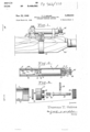
- Fig. 1 is a fragmentary side elevational view of a firearm having a sighting device mounted thereon.
- Fig. 2 is a longitudinal sectional view of the night sighting device.
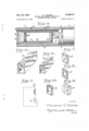
- Fig. 3 is an enlarged exploded. view showing the details of the switch..
- Fig. 4 is an enlarged detail view in longitudinal section showing the collimator assembled to the tubular housing.
- Fig. 5 is an isometric view of the collimator housing.
- Fig. 6 is an isometric view showing the liner 7 contained within the collimator.
- Fig. 7 is an isometric view of the retlcle.
- Fig. 8 is an isometric view of one'of the diaphragms.
- Fig. 9 is an isometric view of the lens.
- Fig. 1D is anisometric view of the lens retainer.
- Fig. 11 is a schematic diagram of the wiring circuit.
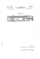
- Fig. 12 is a fragmentary detailed view of an alternate light source for illuminating the reticle shown in longitudinal section.
- Fig. 2 there is shown in assembled relation a sight tube I embodying this invention.
- Tube I is counterbored as shown at 2 and such counterbore produces a shoulder 3.
- Threads 4 are pro- .vided on the interior surface of the right end of tube I as shown in Figs. 2 and 3 while .on the left end of tube i there is provided an antube and near the, end thereof for a purpose to be later described.
- Lamp 6 is provided to illuminate the reticle of a collimator 8 as will be later described.
- Lamp 6 is horizontally secured to a disk 9 byscrewing such into athreaded axial hole I0, disk 9 preferably being made of brass.
- Disk 9 with lamp 6 secured thereto is inserted in the counterbored portion 2 of tube I so that disk 9 abuts shoulder 3 and lamp 8 faces collimator 8, disk 9 thereby grounding lamp 6 to tube I.
- Eattery I is placed adjacent disk 9 so that the positive terminal thereof contacts the baseof lamp 8.
- a threaded plug I I is screwed into threads 4 of tube I.
- Such plug is provided with an integral, horizontally disposed, forwardly extending head portion I2 and a transverse slot 20 is provided on the face thereof.
- An axial hole I3 is likewise provided in plug II and the inwardly facing end of such hole is counterbored as shown at I4.
- a switch:v 45 is inserted inhole I3 and comprises a headed plunger I5. a helical spring I8, and a knob Ill.
- the head portion of plunger I5 with spring 'I 6 in abutting relation rests within .counterbore I4.
- the stem portion of plunger I5 projects forwardly from plug II and knob I8- is secured by threads thereto.
- a washer I! of electrical insulating material is placed between the base of battery I and plug II to prevent grounding. spring I 6 biases the head portion of plunger I5 through washer I1 into contact with the base of battery 1 thereby closing the circuit.
- a transverse pin I9 is secured insultable fashion to the stem portion of plunger I5.
- pin I9 engages transverse slot 2:: in. head I2 of plug when plunger l5 contacts the base of battery I.
- plungerv I5 is pulled outwardly away from battery 1 against the bias of spring I6 whereupon knob I8 is rotated so that pin I9 is disposed across transverse slot- 20 oi plug II, thus plunger I 5 is restrained from contacting the baseof battery 1.
- the intensity of illumination of lamp 6 may be readily varied by any conventional variable resistance 46 shown only in a. schematic wiring diagram illustrated in Fig. 11.
- Collimator 8 comprises a tube H; alens 22 and a reticle 23 as shown in Fig. 4.
- is'preierably of rectangular configuration.
- Retinular groove 5 on the inner periphery of such ole 23 comprises a glass plate, silver and copper plated on one side and such metallically coated end of the tube.
- . 3 side is engraved with a vertical and horizontal line which intersects in the center thereof.
- Reticle 23. is placed in the forward end of tube 2
- a lens retainer 25 surrounds lens 22 and the other end of tube 2
- a plurality of diaphragms 21 may be placed be-- tween separator 25 and lens 22 until proper adjustment is obtained.
- collimator B is assembled to tube l with reticle 23 facing lamp 6 and is secured therein by two screws 24 as shown in Fig. 4.
- the lamp 6 is readily lighted by turning knob l8 of switch 45 so that pin 19 slides into slot 20 on plug H, thus permitting the bias of spring 16 to force plunger l5 into contact with the base of battery 1 thereby closing the circuit.
- Illumination from lamp 6 silhouettes reticle 23 so that such reticle is sharply defined against a brilliant background.
- An alternative method for illuminating reticle 23 utilizesthe light produced by the bombardment of alpha particles emanating from a radio active material on zinc sulphide or other suitable material.
- the light. therefrom is concentrated on reticle 23 by an arrangement shown in Fig. 12 and comprises mounting a truncated cone 28 of a transparent plastic material known as Lucite within counterbore 2 of tube I.
- Light rays pass through such material in much the same manner that water passes through a pipe, the light rays being conveniently bent in any desired direction.
- Truncated cone 28 having a slope of about 65 with respect to the base thereof has been found to produce the. optimum intensity of light concentr-ation on the reticle therein.
- the base of such truncated cone 28 is preferably concave as shown at 4! and is coated with zinc sulphide or other suitable material.
- Truncated cone 28 may be secured within counterbored portion 2 of tube I by suitable rings 30 placed on opposite sides of an integral annular flange-29 provided near the base of truncated cone 28.
- a cylinder 3! mounted within counterbore 2 of tube l and oppositely disposed to the base of truncated cone 28 is a cylinder 3!.
- Such cylinder may be solid or preferably may be constructed of two disks 32 and 33 connected by a tube 34.
- Disks 32 and 33 and tube 34 may be of any suitable material such as metal or plastic and are secured by any-suitable means.
- a threaded bearing plug 35 provided with a threaded axial hole 35 is screwed into the threaded end of tube l and in such hole there is screwed a threaded rod 31.
- One end of rod 31 is rotatably secured to disk 33 of cylinder 3
- Rotation of knob 38 likewise rotates rod 31 thereby effecting longitudinal displacement of cylinder 3! by the threaded cooperation of such rod with threaded hole 36.
- a radioactiv material is coated on the end of cylinder 31 facing the base of cone 28 and the alpha particles emitted by such radioactive material bombard the zinc sulphide material adhering to the base of trun-
- the lens 22 is placed in the 4 cated cone 28 thus producing a luminous glow. The light so produced passes through the "Lucite cone 28 and is projected against reticle-23.
- the light gathered by truncated cone 28 is concentrated and greatly intensified when it comes out the rear 01' small end of such cone.
- the in tensity of such light however can be readily varied by moving cylinder 31 .closer to or farther away from the base of cone 28 by means of threaded rod 31.
- the intensity of light can be varied to suit any particular outside light condition.
- Tube with collimator 8 and either light source assembled thereto is mounted on the firearm preferably substantially ahead of the usual rear sight.
- a base 39 which is conveniently shaped to surround the handguard of a firearm 40 is secured thereto by a suitable clamp M as shown in Fig. 1.
- Conventional telescope mounts 42 and 43 are suitably mounted on top of base 33 and tube l is sl'idably secured within such mounts.
- the rear mount 43 is preferably adjustable for windage and elevation to facilitate alignment of the axis of collimator 8 with the bore of firearm do and the target.
- the rifle is then sighted by keeping the other eye focused on the target and moving the rifle until the reticle is seen by the sighting eye appears to be superim posed on the target.
- the lens mounted within the sight tube, the lens being arranged to bring said reticle into sharp focus whereby the collimation axis may be clearly defined, the improvement comprising a light gath ering body of light pervious material adapted to be mounted Within the sight tube ahead. of the reticle, said light gathering body comprising a truncated cone having a forwardly facing concave base coated with zinc sulphide or other material capable of emitting a luminous glow when exposed to a radioactive material, a second body slidably mounted within the tube disposed ahead of said light gathering body, said second body having a.
- said light gathering body adapted to concentrate light produced by the luminous glow on the reticle thereby sharply silhouetting the reticle, and means for longitudinall traversing said second body whereby the brilliancy of the lu minous glow can be varied to suit surrounding light conditions.
- a sighting device for a firearm having a sight .tube and a collimator therein, the improvement comprising a truncated cone-shaped lens of light-pervious material mounted within the sight tubev ahead of the collimator, said lens having a forwardly disposed concave face coated with zinc sulphide or other material capable of emitting a luminous glow when exposed to a radioactive ma-- I REFERENCES CITED,
Description
Nov. 22, 194-9 Filed March 22, 1946 T. T. HOLME' 2,433,541 RETICLE ILLUMIHATING SOURCE FOR FIREARM- SIGHTING DEVICES 3 Sheets-Sheet 2 FigAL gwuwww'm Thmmtls T.Htalme wflwvmmw Nov. 22, 1949 Filed March 22. 1946' T. T. HOLME 2,488,541 RE'IICLE ILLUMINATING SOURCE FOR FIREARM SIGHTING DEVICES 3 Sheets-Sheet 3 I TEE-11311112 Patented Nov. 22, 1949 RETICLE ILLUMINATING sermon FOR FIREARM sron'rnzo navrcss Thomas '1. Holme, Springfield, Maso.-
Application March 22, 1946, SerlalNo. 656,242
2 Claims. ((11.250-411) (Granted under, theac't of March}, 1883, as amendedAprilSO, 1928; 370 0. G. 757) The invention described herein may be manufeatured and .used by or for the Government for governmental purposes, without the payment to me of any royalty thereon.
The sighting of firearms at night or when light is very poor hasalways been a difficult. problem. The ability of the eye to accurately align a rear sight. aperture, 9. front sight blade and a. target requires reasonably good illumination, especially on the sighting elements, hence night firing has.
. always been a haphazard operation with results very uncertain.
This invention accordingly provides means whereby the difficulties of night shooting can be largely overcome and a rifle can be accurately aimed whenever there is light enough to dennit'ely discern the target with the unaided eye.
The specific nature of the invention as well as other objects and advantages thereof will clearly appear from a description of a preferred embodiment as shown in-the accompanying drawings in which:
Fig. 1 is a fragmentary side elevational view of a firearm having a sighting device mounted thereon.
Fig. 2 is a longitudinal sectional view of the night sighting device.
.Fig. 3 is an enlarged exploded. view showing the details of the switch..
Fig. 4 is an enlarged detail view in longitudinal section showing the collimator assembled to the tubular housing. Fig. 5 is an isometric view of the collimator housing.
Fig. 6 is an isometric view showing the liner 7 contained within the collimator.
Fig. 7 is an isometric view of the retlcle.
Fig. 8 is an isometric view of one'of the diaphragms.
Fig. 9 is an isometric view of the lens.
Fig. 1D is anisometric view of the lens retainer.
Fig. 11 is a schematic diagram of the wiring circuit.
Fig. 12 is a fragmentary detailed view of an alternate light source for illuminating the reticle shown in longitudinal section.
In Fig. 2 there is shown in assembled relation a sight tube I embodying this invention. Tube I is counterbored as shown at 2 and such counterbore produces a shoulder 3. Threads 4 are pro- .vided on the interior surface of the right end of tube I as shown in Figs. 2 and 3 while .on the left end of tube i there is provided an antube and near the, end thereof for a purpose to be later described.
In the counterbored portion 2 of tube I an electric lamp 8 and a drycell battery I are inserted. Lamp 6 is provided to illuminate the reticle of a collimator 8 as will be later described. Lamp 6 is horizontally secured to a disk 9 byscrewing such into athreaded axial hole I0, disk 9 preferably being made of brass. Disk 9 with lamp 6 secured thereto is inserted in the counterbored portion 2 of tube I so that disk 9 abuts shoulder 3 and lamp 8 faces collimator 8, disk 9 thereby grounding lamp 6 to tube I. Eattery I is placed adjacent disk 9 so that the positive terminal thereof contacts the baseof lamp 8.
A threaded plug I I is screwed into threads 4 of tube I. Such plug is provided with an integral, horizontally disposed, forwardly extending head portion I2 and a transverse slot 20 is provided on the face thereof. An axial hole I3 is likewise provided in plug II and the inwardly facing end of such hole is counterbored as shown at I4.
A switch:v 45 is inserted inhole I3 and comprises a headed plunger I5. a helical spring I8, and a knob Ill. The head portion of plunger I5 with spring 'I 6 in abutting relation rests within .counterbore I4. The stem portion of plunger I5 projects forwardly from plug II and knob I8- is secured by threads thereto. A washer I! of electrical insulating material is placed between the base of battery I and plug II to prevent grounding. spring I 6 biases the head portion of plunger I5 through washer I1 into contact with the base of battery 1 thereby closing the circuit.
To hold switch 45 open, a transverse pin I9 is secured insultable fashion to the stem portion of plunger I5. Thus pin I9 engages transverse slot 2:: in. head I2 of plug when plunger l5 contacts the base of battery I. To open the circult, plungerv I5 is pulled outwardly away from battery 1 against the bias of spring I6 whereupon knob I8 is rotated so that pin I9 is disposed across transverse slot- 20 oi plug II, thus plunger I 5 is restrained from contacting the baseof battery 1.
The intensity of illumination of lamp 6 may be readily varied by any conventional variable resistance 46 shown only in a. schematic wiring diagram illustrated in Fig. 11.
Collimator 8 comprises a tube H; alens 22 and a reticle 23 as shown in Fig. 4. Tube 2| is'preierably of rectangular configuration. Retinular groove 5 on the inner periphery of such ole 23 comprises a glass plate, silver and copper plated on one side and such metallically coated end of the tube.
. 3 side is engraved with a vertical and horizontal line which intersects in the center thereof. Reticle 23. is placed in the forward end of tube 2| and the end of such tube is crimped. thereby securing the ,reticle against displacement from that other end of tube 21 and is separated from reticle 23 by a tubular separator 25. A lens retainer 25 surrounds lens 22 and the other end of tube 2| is crimped to secure objective lens 22'to collimator 8. To bring the reticle 23 into sharp focus when viewed through the rear end of collimator 8, a plurality of diaphragms 21 may be placed be-- tween separator 25 and lens 22 until proper adjustment is obtained.
collimator B is assembled to tube l with reticle 23 facing lamp 6 and is secured therein by two screws 24 as shown in Fig. 4. A suitable adhesive pressed into annular groove 5 against the end of collimator 8 excludes foreign matter and water. The lamp 6 is readily lighted by turning knob l8 of switch 45 so that pin 19 slides into slot 20 on plug H, thus permitting the bias of spring 16 to force plunger l5 into contact with the base of battery 1 thereby closing the circuit. Illumination from lamp 6 silhouettes reticle 23 so that such reticle is sharply defined against a brilliant background. y
An alternative method for illuminating reticle 23 utilizesthe light produced by the bombardment of alpha particles emanating from a radio active material on zinc sulphide or other suitable material. The light. therefrom is concentrated on reticle 23 by an arrangement shown in Fig. 12 and comprises mounting a truncated cone 28 of a transparent plastic material known as Lucite within counterbore 2 of tube I. Light rays pass through such material in much the same manner that water passes through a pipe, the light rays being conveniently bent in any desired direction.
Truncated cone 28 having a slope of about 65 with respect to the base thereof has been found to produce the. optimum intensity of light concentr-ation on the reticle therein. The base of such truncated cone 28 is preferably concave as shown at 4! and is coated with zinc sulphide or other suitable material. Truncated cone 28 may be secured within counterbored portion 2 of tube I by suitable rings 30 placed on opposite sides of an integral annular flange-29 provided near the base of truncated cone 28.
Also mounted within counterbore 2 of tube l and oppositely disposed to the base of truncated cone 28 is a cylinder 3!. Such cylinder may be solid or preferably may be constructed of two disks 32 and 33 connected by a tube 34. Disks 32 and 33 and tube 34 may be of any suitable material such as metal or plastic and are secured by any-suitable means.
A threaded bearing plug 35 provided with a threaded axial hole 35 is screwed into the threaded end of tube l and in such hole there is screwed a threaded rod 31. One end of rod 31 is rotatably secured to disk 33 of cylinder 3| and a knurled knob 38 is fixedly secured to the outwardly projecting end of rod 31.
Rotation of knob 38 likewise rotates rod 31 thereby effecting longitudinal displacement of cylinder 3! by the threaded cooperation of such rod with threaded hole 36. A radioactiv material is coated on the end of cylinder 31 facing the base of cone 28 and the alpha particles emitted by such radioactive material bombard the zinc sulphide material adhering to the base of trun- The lens 22 is placed in the 4 cated cone 28 thus producing a luminous glow. The light so produced passes through the "Lucite cone 28 and is projected against reticle-23.
The light gathered by truncated cone 28 is concentrated and greatly intensified when it comes out the rear 01' small end of such cone. The in tensity of such light however can be readily varied by moving cylinder 31 .closer to or farther away from the base of cone 28 by means of threaded rod 31. Thus the intensity of light can be varied to suit any particular outside light condition.
Tube with collimator 8 and either light source assembled thereto is mounted on the firearm preferably substantially ahead of the usual rear sight. A base 39 which is conveniently shaped to surround the handguard of a firearm 40 is secured thereto by a suitable clamp M as shown in Fig. 1. Conventional telescope mounts 42 and 43 are suitably mounted on top of base 33 and tube l is sl'idably secured within such mounts. The rear mount 43 is preferably adjustable for windage and elevation to facilitate alignment of the axis of collimator 8 with the bore of firearm do and the target.
To use the sight herein described the first looks at the target with both eyes and brings the rifle into position so that the collimator intercepts the vision of the sighting eye. The rifle is then sighted by keeping the other eye focused on the target and moving the rifle until the reticle is seen by the sighting eye appears to be superim posed on the target. The vision Of one eye being intercepted by the collimator and the light rays from the collimator being parallel, the eyes will automatically focus on the target.
It is, of course, essential that the sighting device be correctly mounted and accuratel adj ustecl on the rifle the same. as any other type of sight since the accuracy of the system can be no greater than the accuracy of the mounting.
It is therefore apparent from the above description and the appended drawings that the above described invention provides a means whereby a rifle can be accurately aimed at a target in poor or failing light.
I claim: s
g 1. In a sighting device for "a firearm having, a sight tube adapted to be mounted on the firearm, a reticle secured within the sight tube, a
lens mounted within the sight tube, the lens being arranged to bring said reticle into sharp focus whereby the collimation axis may be clearly defined, the improvement comprising a light gath ering body of light pervious material adapted to be mounted Within the sight tube ahead. of the reticle, said light gathering body comprising a truncated cone having a forwardly facing concave base coated with zinc sulphide or other material capable of emitting a luminous glow when exposed to a radioactive material, a second body slidably mounted within the tube disposed ahead of said light gathering body, said second body having a. face coated with a radioactive material opposed to said zinc sulphide coated base whereby alpha, particles from said radioactive material bombard the zinc sulphide to produce the luminous glow, said light gathering body adapted to concentrate light produced by the luminous glow on the reticle thereby sharply silhouetting the reticle, and means for longitudinall traversing said second body whereby the brilliancy of the lu minous glow can be varied to suit surrounding light conditions.
2. In a sighting device for a firearm having a sight .tube and a collimator therein, the improvement comprising a truncated cone-shaped lens of light-pervious material mounted within the sight tubev ahead of the collimator, said lens having a forwardly disposed concave face coated with zinc sulphide or other material capable of emitting a luminous glow when exposed to a radioactive ma-- I REFERENCES CITED,
The following references are of record in the file of this patent: v
UNITED STATES PATENTS Number Name Date 683,203 Grubb Sept. 24, 1901 863,287 Kunz Aug. 13, 1907 1,302,353 Friedrich Apr. 29, 1919 1,442,015 Tillyer -.Jan. 9, 1923 1,610,532 Russell et a1. 1 Dec. 14, 1926 2,240,156 Fel'dm'an Apr. 29, 1941 2,293,138 Hayward Aug. 18, 1942
Priority Applications (1)
| Application Number | Priority Date | Filing Date | Title |
|---|---|---|---|
| US656242A US2488541A (en) | 1946-03-22 | 1946-03-22 | Reticle illuminating source for firearm sighting devices |
Applications Claiming Priority (1)
| Application Number | Priority Date | Filing Date | Title |
|---|---|---|---|
| US656242A US2488541A (en) | 1946-03-22 | 1946-03-22 | Reticle illuminating source for firearm sighting devices |
Publications (1)
| Publication Number | Publication Date |
|---|---|
| US2488541A true US2488541A (en) | 1949-11-22 |
Family
ID=24632234
Family Applications (1)
| Application Number | Title | Priority Date | Filing Date |
|---|---|---|---|
| US656242A Expired - Lifetime US2488541A (en) | 1946-03-22 | 1946-03-22 | Reticle illuminating source for firearm sighting devices |
Country Status (1)
| Country | Link |
|---|---|
| US (1) | US2488541A (en) |
Cited By (14)
| Publication number | Priority date | Publication date | Assignee | Title |
|---|---|---|---|---|
| US2706335A (en) * | 1949-09-01 | 1955-04-19 | Herbert H Munsey | Gun sight |
| US2727309A (en) * | 1952-12-13 | 1955-12-20 | Ralph M Jenkins | Reversible gun sight |
| US2925657A (en) * | 1956-08-27 | 1960-02-23 | Walter H Stenby | Sighting devices |
| US3121163A (en) * | 1962-05-07 | 1964-02-11 | Glenn E Rickert | Luminous reticle |
| US3784817A (en) * | 1971-05-11 | 1974-01-08 | Atlantic Richfield Co | Radio luminescent sighting arrangement |
| US3937968A (en) * | 1969-05-02 | 1976-02-10 | Singlepoint U.S.A. Inc. | Optical aiming device employing radioluminous material |
| US3938875A (en) * | 1969-05-09 | 1976-02-17 | Nils Inge Algot Ruder | Sight for use on hand firearms and a method of using it |
| US4695159A (en) * | 1984-02-07 | 1987-09-22 | Focalpoint Armoury Limited | Improvements in sights for firearms and other articles |
| US4837633A (en) * | 1987-06-22 | 1989-06-06 | Parra Jorge M | Electronic boundary framing device and method |
| US4866849A (en) * | 1987-06-22 | 1989-09-19 | Pioneer Data Processing, Inc. | Surveying target with high intensity discharge lamp |
| US5279061A (en) * | 1992-07-15 | 1994-01-18 | Progenics Corporation | Sight apparatus for firearms |
| US8635800B2 (en) | 2010-12-14 | 2014-01-28 | Trijicon, Inc. | Gun sight |
| US8656631B2 (en) | 2011-01-17 | 2014-02-25 | Trijicon, Inc. | Fiber optic shotgun sight |
| US9404711B1 (en) * | 2012-06-12 | 2016-08-02 | Crimson Trace Corporation | Reusable laser sighting device adapter for rocket launcher |
Citations (7)
| Publication number | Priority date | Publication date | Assignee | Title |
|---|---|---|---|---|
| US683203A (en) * | 1900-12-26 | 1901-09-24 | Howard Grubb | Sighting device for guns. |
| US863287A (en) * | 1903-12-23 | 1907-08-13 | George F Kunz | Device for effecting illumination. |
| US1302353A (en) * | 1917-09-20 | 1919-04-29 | Conrad Friedrich | Luminous hair-line. |
| US1442015A (en) * | 1919-07-08 | 1923-01-09 | American Optical Corp | Gun sight |
| US1610532A (en) * | 1922-04-18 | 1926-12-14 | Russell Herbert Owen | Mirror gun sight |
| US2240156A (en) * | 1937-07-17 | 1941-04-29 | Jacob B Feldman | Apparatus for determining the minimum light visible |
| US2293138A (en) * | 1940-05-01 | 1942-08-18 | Rca Corp | Indicator |
-
1946
- 1946-03-22 US US656242A patent/US2488541A/en not_active Expired - Lifetime
Patent Citations (7)
| Publication number | Priority date | Publication date | Assignee | Title |
|---|---|---|---|---|
| US683203A (en) * | 1900-12-26 | 1901-09-24 | Howard Grubb | Sighting device for guns. |
| US863287A (en) * | 1903-12-23 | 1907-08-13 | George F Kunz | Device for effecting illumination. |
| US1302353A (en) * | 1917-09-20 | 1919-04-29 | Conrad Friedrich | Luminous hair-line. |
| US1442015A (en) * | 1919-07-08 | 1923-01-09 | American Optical Corp | Gun sight |
| US1610532A (en) * | 1922-04-18 | 1926-12-14 | Russell Herbert Owen | Mirror gun sight |
| US2240156A (en) * | 1937-07-17 | 1941-04-29 | Jacob B Feldman | Apparatus for determining the minimum light visible |
| US2293138A (en) * | 1940-05-01 | 1942-08-18 | Rca Corp | Indicator |
Cited By (15)
| Publication number | Priority date | Publication date | Assignee | Title |
|---|---|---|---|---|
| US2706335A (en) * | 1949-09-01 | 1955-04-19 | Herbert H Munsey | Gun sight |
| US2727309A (en) * | 1952-12-13 | 1955-12-20 | Ralph M Jenkins | Reversible gun sight |
| US2925657A (en) * | 1956-08-27 | 1960-02-23 | Walter H Stenby | Sighting devices |
| US3121163A (en) * | 1962-05-07 | 1964-02-11 | Glenn E Rickert | Luminous reticle |
| US3937968A (en) * | 1969-05-02 | 1976-02-10 | Singlepoint U.S.A. Inc. | Optical aiming device employing radioluminous material |
| US3938875A (en) * | 1969-05-09 | 1976-02-17 | Nils Inge Algot Ruder | Sight for use on hand firearms and a method of using it |
| US3784817A (en) * | 1971-05-11 | 1974-01-08 | Atlantic Richfield Co | Radio luminescent sighting arrangement |
| US4695159A (en) * | 1984-02-07 | 1987-09-22 | Focalpoint Armoury Limited | Improvements in sights for firearms and other articles |
| US4837633A (en) * | 1987-06-22 | 1989-06-06 | Parra Jorge M | Electronic boundary framing device and method |
| US4866849A (en) * | 1987-06-22 | 1989-09-19 | Pioneer Data Processing, Inc. | Surveying target with high intensity discharge lamp |
| US5279061A (en) * | 1992-07-15 | 1994-01-18 | Progenics Corporation | Sight apparatus for firearms |
| US8635800B2 (en) | 2010-12-14 | 2014-01-28 | Trijicon, Inc. | Gun sight |
| US8635801B2 (en) | 2010-12-14 | 2014-01-28 | Trijicon, Inc. | Gun sight |
| US8656631B2 (en) | 2011-01-17 | 2014-02-25 | Trijicon, Inc. | Fiber optic shotgun sight |
| US9404711B1 (en) * | 2012-06-12 | 2016-08-02 | Crimson Trace Corporation | Reusable laser sighting device adapter for rocket launcher |
Similar Documents
| Publication | Publication Date | Title |
|---|---|---|
| US2488541A (en) | Reticle illuminating source for firearm sighting devices | |
| US2844710A (en) | Sighting attachment for firearms | |
| US3672782A (en) | Riflescope with multiple reticles selectively projected on a target | |
| US3362074A (en) | Binocular front sight for firearms | |
| US2085732A (en) | Automatic night sighting device for firearms | |
| US3813790A (en) | Sighting means for firearms | |
| US4876816A (en) | Target illuminating aiming system | |
| US5653034A (en) | Reflex sighting device for day and night sighting | |
| US4618221A (en) | Adjustable reticle device | |
| US20220244520A1 (en) | Dual focal plane reticles for optical sighting devices | |
| US3974585A (en) | Gun sight night lighting attachment | |
| US5493450A (en) | Sighting instrument | |
| EP0239700A2 (en) | Sighting device | |
| US2596522A (en) | Illuminated gun sight | |
| US2101479A (en) | Night target range finder | |
| US4375725A (en) | Optical sight | |
| US3880529A (en) | Sighting device | |
| GB1192786A (en) | Improvements in or relating to Telescopic Sight for Gun-Sighting Mechanisms | |
| US2385649A (en) | Firearm sight | |
| US3938875A (en) | Sight for use on hand firearms and a method of using it | |
| US2472809A (en) | Illuminated reticle attachment for telescopes | |
| US2128526A (en) | Firearms sighting device | |
| US2336718A (en) | Luminous gun sight | |
| JPS60182406A (en) | Sight device | |
| US6208461B1 (en) | Daytime/nighttime arms sight |