US683078A - Means for transporting rigid bodies. - Google Patents
Means for transporting rigid bodies. Download PDFInfo
- Publication number
- US683078A US683078A US3633700A US1900036337A US683078A US 683078 A US683078 A US 683078A US 3633700 A US3633700 A US 3633700A US 1900036337 A US1900036337 A US 1900036337A US 683078 A US683078 A US 683078A
- Authority
- US
- United States
- Prior art keywords
- cylinders
- platform
- trucks
- carriage
- series
- Prior art date
- Legal status (The legal status is an assumption and is not a legal conclusion. Google has not performed a legal analysis and makes no representation as to the accuracy of the status listed.)
- Expired - Lifetime
Links
- 239000007788 liquid Substances 0.000 description 15
- 239000012530 fluid Substances 0.000 description 12
- 230000008093 supporting effect Effects 0.000 description 11
- 230000033001 locomotion Effects 0.000 description 5
- 238000010276 construction Methods 0.000 description 3
- XLYOFNOQVPJJNP-UHFFFAOYSA-N water Substances O XLYOFNOQVPJJNP-UHFFFAOYSA-N 0.000 description 3
- 238000009432 framing Methods 0.000 description 2
- 238000000034 method Methods 0.000 description 2
- 229910000831 Steel Inorganic materials 0.000 description 1
- 230000001174 ascending effect Effects 0.000 description 1
- 230000007246 mechanism Effects 0.000 description 1
- 239000010959 steel Substances 0.000 description 1
Images


Classifications
-
- B—PERFORMING OPERATIONS; TRANSPORTING
- B63—SHIPS OR OTHER WATERBORNE VESSELS; RELATED EQUIPMENT
- B63B—SHIPS OR OTHER WATERBORNE VESSELS; EQUIPMENT FOR SHIPPING
- B63B71/00—Designing vessels; Predicting their performance
Definitions
- T0 ctZZ whom', t may concern:
- My invention is adapted especially for use in connection with marine railways, but is applicable also wherever it is desirable to move long and rigid bodies or structures upon wheels along a railway having vertical curves or grades of short radii, the object of the inventiou being to provide means for compensating for the undulating motion of the trucks,
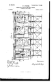
- FIG. 1 is a longitudinal View in elevation of the carriage on a horizontal way.
- Fig. 2 is a longitudinal View in elevation of a section of railway, including vertical curves of short radius and a carriage thereon.
- Fig. 3 is an end View of the carriage and a section of the structure which supports the railway.
- Fig. 4 is a plan View of portions of the carriage, showing one end and part of the central section broken off. Fig.
- Fig. 5 is a longitudinal elevation of the carriage, showing sections of the cylinders and plungers on a vertical curve, the track and substructure supporting the same, also the trucks and the link systems which connect the trucks together, and the pipes which connect together' serially the several cylinders.
- Fig. 6 is a side elevation of two cylinders in section, their connecting-pipe, also sections of the :yoke and the truss-framingattheendofthecarriage. Fig.
- FIG. 7 is a plan view of that portion of the carriage shown in elevation in Fig. 6, showing the manner of counteracting the thrust upon the end cylinders and showing also the mechanisms by which the cylinders are su pplied with the liquid which supports the load.
- Fig. Si a side elevation of one end of the carriage structure, showing how it is framed.
- Fig. 9 is a sectional view of the upper portion of Fig. 8, also illustrating the framing thereof.
- Figs. l0 and 11 are details of the two preceding views.
- Figs. 12 and 13 are further illustrations of the methods of framing the structure.
- Fig. 14 is a plan View of a portion of two trucks, showing the connections between them. Fig.
- Fig. 15 is a sectional view of a ballast-tank with its valve.
- Figs. 16 and 17 are a plan and elevation of the tank, pump, and pipes forsupplying the cylinders with liquid.
- Fig. 1S is au elevation of the devices used in hauling the carriage, and
- Fig. 19 is a plan view of portions thereof.
- Fig. 20 is an end View of the cylinders employed for automatically adjusting the strains on the vhaulingcables
- Fig. 21 is a sectional elevation of the cylinders, plu'ugers, ⁇ and supply-pipe thereof.
- Fig. 22 shows the mode of fastening the end and longitudinal trusses together at the corners of the carriage, and Fig. 23 the mode of fastening the same together at the intermediate joints, and
- Fig. 24 shows the plates used at the latter.
- the platform A maybe of any suitable form, but is shown as ⁇ ofthe type of structure well known as a floating dock. In this instance, howeveninstead of floating upon a body of water it is supported by a liquid or other Huid confined in several seriesof cylinders C, which are secured rigidly to the bottom of the platform A. These cylinders are connected with each other bymeans of pipes D, which allow a free circulation of the liquid or other fluid through each series of cylinders longitudinally of the carriage, but not transversely to the carriage. The liquid or other uid rests upon plungers E in the cylinders, (shown in section at the left-hand end of Fig.
- the rails I and beams J are illustrated partially in Fig. 2 as arranged so as to form three horizontal planes K, connected by four vertical curves Lto twoinclined planes M in such a manner as to form a continuous track. They can be made of any suitable length, and a less or greater number of planes may be employed.
- the gradients are preferably one foot vertical to ten horizontal, but may be of any other grade.
- DeckbeamsB extending the entire length of the platform A on either side thereof', tend to stiffen it longitudinally. They are secured to the side trusses T by means of the straps H, the keys a, and the wedges c. They also serve tohold the ends of the transverse deck-beams Q firmly between thelongtudinal deck-beams B and the trusses T. The transverse deckbeams Q serve to tie together all the longitudinal trusses and form a platform A, upon whichthe loadissupported. Theyaresecured to the intermediate longitudinal trusses, as illustrated in Fig. 3, by means of straps V and by means of the keys a, wedges c, and cross-bars f, Fig. l1. These beams are also secured to and form the hanging support of the cylinders C.
- the boxes g, on which the connecting-rods F are journaled, (which are inserted into the said truck-frames,) are thus placed low down in the structure,thereby therefore means must be provided whereby the said cylinders at both ends of any series will be braced firmly in their respective positions, so as to resist the thrust occasioned by this pressure.
- yokes W are provided, which bear centrally along the line of pressure upon the outer side of the end cylinders.
- liquid can be delivered through the small transverse feed-pipe j, which constitutes a connection 4between the said pump and the several series of main pipes D.
- a stop-cock K' At each junction between the said feed-pipe and the said main pipes is placed a stop-cock K', whereby the supply of liquid may be turned off from any of the pipes D whenever such pipe has receivedtheproperquantum.
- Bythismeans it is possible to supply any series of the pipes D and cylinders C without oversupplying any other series,and thus each 4series may be fitted ⁇ to perform its part in sustainment of the load and in maintaining the proper position of the platform.
- a special de- See Figs. 18, 19, 20, and 21.
- This consists of several parts.
- the pivot Z connects to the truck-frame Gr, by means of the forked connecting-pieces fm, ⁇ a
- hollow hauling-bar n which extends. transversely the whole width of the carriage at each end thereof.
- These forked connectingpieces are secured rigidly to the hauling-bar 'n at their outer extremity.
- the long arm of the said fork is so shaped'and arranged that at its upper end it maycome into contact with a bar o, secured to the upper side of the hangers R, thus aordin g a detent which pre- IOO vents too great adescent of the hook p.
- This hook is so adjusted as to engage with the clevis q of the cable r.
- the said clevis is formed witha hooked lower side s, which engages with the hook-shaped detent t.
- the latter is fastened between the rails I of the track upon which the carriage moves.
- the carriage in ascending reaches the point where the hook p engages with the clevispins u, its further progress picks up the cable o", which is then lifted from the roller o to such position as the strain thereupon may cause it to assume.
- the inequality is corrected by the action of the plungers w in the cylinders fr.'
- the hook p is a portion of the strap y, which latter extends past the cylinders x and continues around the cross-bar z, which is secured to the plungers w.
- any undue strain on any one of the cables r causes the plungers w to penetrate farther into the cylinders x, with the result that some of the liquid contained therein will be forced into the hollow hauling-bar 'n and thence distributed through the other cylinders at', which are mounted thereon. This operation will continue until any unequal disposition of the load on any cable is remedied.
- the apparatus herein described may be has been found necessary to divide both carf riages and boats into sections and connect the several sections together by hinges, thus only allowing of specially-constructed boats to be used thereon.
- the mode of propulsion employed with the carriage described may be cable-hauling devices, as illustrated, or any other of the wellknown means used in traversing steep grades, and any suitable brake system may be used. Therefore no special devices for propulsion or for brakes are described or illustrated herein.
- the apparatus herein described consisting of railway planes joined by vertical curves, trucks traveling thereon, connectingrods supported by said trucks, plungers on said connecting-rods, and cylinders containing a liquid or other fluid, said cylinders being connected longitudinally of the railway, and a rigid platform supported by said cylinders, substantially as described.
Landscapes
- Chemical & Material Sciences (AREA)
- Engineering & Computer Science (AREA)
- Combustion & Propulsion (AREA)
- Mechanical Engineering (AREA)
- Ocean & Marine Engineering (AREA)
- Handcart (AREA)
Description
vPanama sept. 24,1901.
I0 Sheets-Sheet I.
No. 683,078. Ptented Sept. 24, l90l.
H. C. SPALDING.
MEANS FUR TBANSPORTING RIGID BODIES.
(Appliczion mad Nov. 1s, 1900.) i (No Model.) I0 Sheets-Sheet 2.
f f @i544 'i wh esse? No. 683,078. Patented Sept. 24, |90I.
H. C. SPALDING.
MEANS F08 TBANSPURTING RIGID BODIES.
(Appn'tiun :a1-d Nov. 13, 1900.)
(.No Model.) I0 Sheets-Sheet 3.
Patented Sept..24, |90ll H. C. ASPALIIING. MEANS FUR TBANSPORTIIIG RIGID BODIES.
(Appumion med Nav. 1s, 1900.5
ID Sheets-Sheet 4.
(No Iodel.)
IIIIIIHIIIHHII IIII [III
Il'. 'Il
lll] IIIIII lliz Menton' @f Patented Slept. 24', |901.
H. C. SPALDING.
(Application filed Nov. 13, 1900.)
MEANS FOR TRANSPDRTING RIGID BODIES.
(No Mod-el.)
4TN! NOFUIIS PETERS C0. PDTOLITHO.. WASHINGTON, D. C.
mmflllllw No. 683,078. Patented Sept. 24, |901. H. C. SPALDING.
MEANS FUR TRANSPORTING RIGID BODIES.
(Application filed Nov. 13, 1900.) (No Model.) I0 Sheei's-Sheet 7.
um u
Wit eases.' Q5
. @u www@ No. 683,078. Patented Sept. 24, I90I,
H. C. SPALDING.
MEANS FDR'TBANSPOBTING RIGID BUDIES.
(Application tiled Nov. 13. 1900.) (No Hedel.) I0 Sheets-Sheet 8.
"IIIA mf@ I 'run non-ma versn: c'o, PHo'rou-ruc.. wAsnmsToN. D. c.
No. 683,078. Patented Sept. 24, I90I. H. C. SPALDING.
MEANS FDR TRANSPORTING RIGID B DDIES.
(Application Bled Nov, 18, 1900.)
(No Model.)
lo sheets-Sheet 9.
@Y f@ n/L'zes'esf Inventory TN: MoRms Pmns w.. mmaumq, wnsnmcm. u. c.
No.- 683,078. Patented Sept. 24, IQDI.
H. C. SPALDING. MEANS FDR THANSPORTING RIGID BODIES.
(Applmstion tiled Nov. 13, 1900.)
(No Model.)
lo sheets-sheet lu.
" l. di 15; f 'f "m WH M1' UNirnD STATES PATENT FFICE'.
IIENRY CURTIS SPALDING, OF NEW YORK, N.
IVIEANS FOR TRANSPOR'I'ING `RIGID BODIES.
ssn'oIFIcATIoN 'forming part of Letters Patent No. 683,078, dated september 24, 1901;
.itpnc'atanneaNove'nibefis,1900. sentito. 36.337. ormoni.)
T0 ctZZ whom', t may concern: A
Beit known that I, HENRY CURTIS SPALD- ING, a citizen of the United States, residing at the city of New York, in the county of New York and State of New York, haveinvented certain new and useful Improvements in Means `for Transporting Rigid Bodies, fully described and represented in the following specification andthe accompanying drawings, forming a part of the same.
My invention is adapted especially for use in connection with marine railways, but is applicable also wherever it is desirable to move long and rigid bodies or structures upon wheels along a railway having vertical curves or grades of short radii, the object of the inventiou being to provide means for compensating for the undulating motion of the trucks,
so as to hold the rigid body or structure carried thereby in proper position.
With this object inl View the invention coussts in certain features of construction and combinations of parts, all as fullyl described and specificall y claimed herein.
For a full understanding of the invention I have shown in the accompanying drawings, forming a part of this specification, a coustruction embodying the structural features of the invention in their preferred form, and this con struction will now be described' in connection with the drawings, in which- Figure lis a longitudinal View in elevation of the carriage on a horizontal way. Fig. 2 is a longitudinal View in elevation of a section of railway, including vertical curves of short radius and a carriage thereon. Fig. 3 is an end View of the carriage and a section of the structure which supports the railway. Fig. 4 is a plan View of portions of the carriage, showing one end and part of the central section broken off. Fig. 5 is a longitudinal elevation of the carriage, showing sections of the cylinders and plungers on a vertical curve, the track and substructure supporting the same, also the trucks and the link systems which connect the trucks together, and the pipes which connect together' serially the several cylinders. Fig. 6 is a side elevation of two cylinders in section, their connecting-pipe, also sections of the :yoke and the truss-framingattheendofthecarriage. Fig.
7 is a plan view of that portion of the carriage shown in elevation in Fig. 6, showing the manner of counteracting the thrust upon the end cylinders and showing also the mechanisms by which the cylinders are su pplied with the liquid which supports the load. Fig. Sis a side elevation of one end of the carriage structure, showing how it is framed. Fig. 9 is a sectional view of the upper portion of Fig. 8, also illustrating the framing thereof. Figs. l0 and 11 are details of the two preceding views. Figs. 12 and 13 are further illustrations of the methods of framing the structure. Fig. 14 is a plan View of a portion of two trucks, showing the connections between them. Fig. 15 is a sectional view of a ballast-tank with its valve. Figs. 16 and 17 are a plan and elevation of the tank, pump, and pipes forsupplying the cylinders with liquid. Fig. 1S is au elevation of the devices used in hauling the carriage, and Fig. 19 is a plan view of portions thereof. Fig. 20 is an end View of the cylinders employed for automatically adjusting the strains on the vhaulingcables, and Fig. 21 is a sectional elevation of the cylinders, plu'ugers, `and supply-pipe thereof. Fig. 22 shows the mode of fastening the end and longitudinal trusses together at the corners of the carriage, and Fig. 23 the mode of fastening the same together at the intermediate joints, and Fig. 24 shows the plates used at the latter.
Similar letters refer to si milar parts throughout the several views.
The platform A maybe of any suitable form, but is shown as `ofthe type of structure well known as a floating dock. In this instance, howeveninstead of floating upon a body of water it is supported by a liquid or other Huid confined in several seriesof cylinders C, which are secured rigidly to the bottom of the platform A. These cylinders are connected with each other bymeans of pipes D, which allow a free circulation of the liquid or other fluid through each series of cylinders longitudinally of the carriage, but not transversely to the carriage. The liquid or other uid rests upon plungers E in the cylinders, (shown in section at the left-hand end of Fig.
well-known gas-engines, but opening downward. The lower ends of the con meeting-rods I1` rest upon and are pivotally connected to the trucks G. These trucks may be and are shown as of the usual railway type and rest upon the rails I, which are supported by the beams J. These beams may be supported by` masonry of any suitable construction and be properly tied and braced to each other, so as to constitute an unyielding support to the superstructure. RigidlinksN,seriallyjointed to the corners of the truck-frames O, hold the several trucks in a series to their relative distances from each other, while long connecting-bars P, jointed at b to hangers R, secured to the end trucks of a series, and hangers S, secured to the bottom of' the platform A, hold the trucks under the platform and prevent them from escaping therefrom. Trusses T at the sides and ends below the said platform increase the rigidity thereof. Other trusses suspended longitudinally therefrom between the trucks may also be added for the purpose of' further increasing the strength of the platform to support the burden between the bearings. As in many cases the load may be greater at one'end than at the other, ballast-tanks U are preferably provided. These are so suspended below the platform at each end that they will admit water over their tops when the platform is submerged. Any tendency to depression at one end may be corrected by opening the valve `c, Fig. 15, and allowing the water to escape until such tendency is corrected. It willbe well, however, when placing the burden upon the platform to so locate it that little or no necessity shall arise for such regulation. The rails I and beams J are illustrated partially in Fig. 2 as arranged so as to form three horizontal planes K, connected by four vertical curves Lto twoinclined planes M in such a manner as to form a continuous track. They can be made of any suitable length, and a less or greater number of planes may be employed. The gradients are preferably one foot vertical to ten horizontal, but may be of any other grade. The curves must be of such radii that the plungers E will not bottom in orbe withdrawn from the cylinders C. DeckbeamsB, extending the entire length of the platform A on either side thereof', tend to stiffen it longitudinally. They are secured to the side trusses T by means of the straps H, the keys a, and the wedges c. They also serve tohold the ends of the transverse deck-beams Q firmly between thelongtudinal deck-beams B and the trusses T. The transverse deckbeams Q serve to tie together all the longitudinal trusses and form a platform A, upon whichthe loadissupported. Theyaresecured to the intermediate longitudinal trusses, as illustrated in Fig. 3, by means of straps V and by means of the keys a, wedges c, and cross-bars f, Fig. l1. These beams are also secured to and form the hanging support of the cylinders C.
I prefer to make the truckvice Z is employed.
^ esame frames G of sheet-steel, cut out and struck up in the manner now well known in railwaywork; but they are preferably of the outlines shown in the drawings. The boxes g, on which the connecting-rods F are journaled, (which are inserted into the said truck-frames,) are thus placed low down in the structure,thereby therefore means must be provided whereby the said cylinders at both ends of any series will be braced firmly in their respective positions, so as to resist the thrust occasioned by this pressure. For this purpose yokes W are provided, which bear centrally along the line of pressure upon the outer side of the end cylinders. These yokes are secured firmly to the longitudinal angle-bars Y,Which form part of the upper members of the trusses T. As the said angle-bars extend the entire length of the carriage, the strains at the one end are exactly counterbalanced by the strains at the other end, thus securing the proper stability for the said cylinders at the eXtreme end of any series. For the purpose of readily supplying liquid to the pipes D and the cylinders C the tank Y', Figs. 16 and 17, is placed nearly in the center of the upper part of the carriage. Apump h is connected thereto,operated by the double lever t'. By this means liquid can be delivered through the small transverse feed-pipe j, which constitutes a connection 4between the said pump and the several series of main pipes D. At each junction between the said feed-pipe and the said main pipes is placed a stop-cock K', whereby the supply of liquid may be turned off from any of the pipes D whenever such pipe has receivedtheproperquantum. Bythismeans it is possible to supply any series of the pipes D and cylinders C without oversupplying any other series,and thus each 4series may be fitted` to perform its part in sustainment of the load and in maintaining the proper position of the platform. Whenever it becomes desirable to employ hauling-cables for the purpose of moving the carriage as a means for equalizing strains upon the several cables, a special de- (See Figs. 18, 19, 20, and 21.) This consists of several parts. The pivot Z connects to the truck-frame Gr, by means of the forked connecting-pieces fm,\a
hollow hauling-bar n, which extends. transversely the whole width of the carriage at each end thereof. These forked connectingpiecesare secured rigidly to the hauling-bar 'n at their outer extremity. The long arm of the said fork is so shaped'and arranged that at its upper end it maycome into contact with a bar o, secured to the upper side of the hangers R, thus aordin g a detent which pre- IOO vents too great adescent of the hook p. This hook is so adjusted as to engage with the clevis q of the cable r. The said clevis is formed witha hooked lower side s, which engages with the hook-shaped detent t. The latter is fastened between the rails I of the track upon which the carriage moves. When the carriage in ascending reaches the point where the hook p engages with the clevispins u, its further progress picks up the cable o", which is then lifted from the roller o to such position as the strain thereupon may cause it to assume. When any one of the several cables r is strained more than another,the inequality is corrected by the action of the plungers w in the cylinders fr.' The hook p is a portion of the strap y, which latter extends past the cylinders x and continues around the cross-bar z, which is secured to the plungers w. By this means any undue strain on any one of the cables r causes the plungers w to penetrate farther into the cylinders x, with the result that some of the liquid contained therein will be forced into the hollow hauling-bar 'n and thence distributed through the other cylinders at', which are mounted thereon. This operation will continue until any unequal disposition of the load on any cable is remedied.
The operation will beunderstood from a brief description. The burden to be transported is placed upon the platform in any suitable manner while the carriage is at either of the two ends of the railway and is properly secured thereupon, and then motion is imparted to the carriage. When the carriage arrives at the invert curve, the plungers E over the truck at the forward end of the carriage will force some of the contained liquid or other fluid out of the cylinders in which it is confined into the pipes D, Vand thus rearrange it longitudinally of the carriage by distribution into the other cylinders. This will in turn force the successive plungers downward until the next in series reaches the curve, whereupon the liquid or other fluid contained therein will be distributed until the central truck of the series in its turn reaches the curve. By that time the leading truck will have mounted so far on the invert curve that the plungers for the central truck will be forced farther downward by the pressure, and both the end plungers of the series will have been forced upward as a result of the varying pressures. The reverse of this process will occur when the carriage has ascended the incline to the summit curve; but when the summit plane is attained the contained liquid or fluid will be equalized in each of the cylinders of a series longitudinally of the carriage and the platform will resume its level position. Similar operations will occur at the time of descending from the summit plane over the invert curve to the level termination at the other end.
The apparatus herein described may be has been found necessary to divide both carf riages and boats into sections and connect the several sections together by hinges, thus only allowing of specially-constructed boats to be used thereon.
The mode of propulsion employed with the carriage described may be cable-hauling devices, as illustrated, or any other of the wellknown means used in traversing steep grades, and any suitable brake system may be used. Therefore no special devices for propulsion or for brakes are described or illustrated herein.
It will be understood that the invention is not to be limited to the form or arrangement of the equalizing devices illustrated, but that these may be varied widely without departing from my invention.
What I claim, and desire to secure by Letters Patent of the United States, is-
1. The combination of a rigid burden-carrying platform provided with trucks and fluidcylinders and plungers between the platform and trucks for supporting the platform by fluid contained in the cylinders, substantially as described.
2. The combination of a rigid platform and trucks, cylinders arranged longitudinally of the platform, and plungers in said cylinders supported by the trucks and supporting the platform by iuid contained in said cylinders, substantially as described.
3. The combination of a rigid platform and trucks, cylinders arranged longitudinally of the platform and plungers in said cylinders supported by the trucks and supporting the platform by fluid contained in said cylinders, and a pipe connecting the fluid-spaces of the cylinders throughout the series longitudinally of the platform, substantially as described.
4t. The combination of the trucks, links N at opposite sides of and connecting said trucks, a rigid platform, cylinders arranged longitudinally of the platform and plungers supported by the trucks and support-ing the platform by fluid contained in the cylinders, substantially as described.
5. The combination of the trucks, links N at opposite sides of and connecting said trucks, a rigid platform, cylinders arranged longitudinally of the platform, plungers supported by the trucks and supporting the platform by fluid contained in the cylinders, and a pipe connecting the fluid-spaces of the cylinders throughout the series longitudinally of the platform, substantially as described.
6. The combination of a rigid burden-carrying platform provided with trucks, and fluidcylinders and plungers between the platform and trucks for supporting the former byfluid contained in the cylinders, and liquid-ballast IOO IIO
tanks at opposite ends of the platform with valves for emptying said tanks, substantially as described. p
7. The apparatus herein described, consisting of railway planes joined by vertical curves, trucks traveling thereon, connectingrods supported by said trucks, plungers on said connecting-rods, and cylinders containing a liquid or other fluid, said cylinders being connected longitudinally of the railway, and a rigid platform supported by said cylinders, substantially as described.
8. The combination with a rigid burdencarrying platform, of means for supporting said platform consisting of columns of liquid or other fluid connected together iu series longitudinally of the movement of the platform sothat the column may become shorter or longer by the flow of iiuid through the series, substantially as described.
9. The combination with a rigid burdencarrying platform, of means for supporting said platform consisting of columns of liquid or other liuid arranged in a plurality of series of columns, the columns in each series being arranged and connected together longitudinally of the movement of the platform so that the columns may become shorter or longer by the flow of Iiuid through each series and the columns of the dierent series beingdisconnected so that no flow of fluid is permitted between the columns transversely to the movement of the platform, substantially as described.
10. The combination with a rigid burdencarrying platform, of trucks, duid-cylinders and plun gers between the platform and trucks for supporting the platform by fiuid contained in the cylinders, links N connecting the trucks at opposite sides, and the connectingbars P extending longitudinally of the plateisovs carrying platform provided with trucks, and
longitudinal series of cylinders and plungers between the platform and trucks for supporting the platform by uid contained in the` cylinders, of means whereby fluid may be supplied to any or all of the longitudinal series of cylinders, substantially as and for the purposes set forth. i y
14E. The combination of the trucks and the hollow hauling-bar connected to said trucks with cylinders mounted on said bar and having their duid-spaces connected through the hollow hauling bar, 'substantially as described.
15. The combination of the trucks, the hauling-bar and the cylinders mounted thereupon, with the plungers fitted into the said cylinders and the hook and strap, substantially as described.
16. The combination of the hollow haulingbar, the cylinders mounted thereon, the plungers and the hook and strap with the clevis,
substantially as described.
In testimony whereof I have hereunto set my hand in the presence of two subscribing witnesses.
i HENRY CURTIS SPALDING.
Vitnesses:
C. J. SAWYER, A, A. V. Bomann.`
Priority Applications (1)
| Application Number | Priority Date | Filing Date | Title |
|---|---|---|---|
| US3633700A US683078A (en) | 1900-11-13 | 1900-11-13 | Means for transporting rigid bodies. |
Applications Claiming Priority (1)
| Application Number | Priority Date | Filing Date | Title |
|---|---|---|---|
| US3633700A US683078A (en) | 1900-11-13 | 1900-11-13 | Means for transporting rigid bodies. |
Publications (1)
| Publication Number | Publication Date |
|---|---|
| US683078A true US683078A (en) | 1901-09-24 |
Family
ID=2751621
Family Applications (1)
| Application Number | Title | Priority Date | Filing Date |
|---|---|---|---|
| US3633700A Expired - Lifetime US683078A (en) | 1900-11-13 | 1900-11-13 | Means for transporting rigid bodies. |
Country Status (1)
| Country | Link |
|---|---|
| US (1) | US683078A (en) |
-
1900
- 1900-11-13 US US3633700A patent/US683078A/en not_active Expired - Lifetime
Similar Documents
| Publication | Publication Date | Title |
|---|---|---|
| US3119349A (en) | Track-mounted transport means or systems | |
| NO791421L (en) | TROLLEY FOR USE WHEN TRANSPORTING MODULES FOR CONSTRUCTION OF SHIPS | |
| US3663040A (en) | Small boat carrier | |
| US1972042A (en) | Dump vehicle | |
| US683078A (en) | Means for transporting rigid bodies. | |
| JPH0114158B2 (en) | ||
| US728117A (en) | Ship-railway carriage. | |
| US1944054A (en) | Cableway tower | |
| RU2046733C1 (en) | Self-propelled transporter for moving ship's structural members and ship in two mutually perpendicular directions | |
| US1611419A (en) | Decking device for vehicles | |
| US135972A (en) | Improvement in propulsion of cars | |
| US236563A (en) | James b | |
| US999310A (en) | Lumber-truck loader. | |
| US481405A (en) | Nipple | |
| US485044A (en) | Ipple | |
| US555921A (en) | Elevated railway | |
| US857264A (en) | Device for transporting ships. | |
| US245876A (en) | Apparatus for moving houses | |
| US2347396A (en) | Boat storage system and apparatus | |
| US46784A (en) | Improvement in running-gear of railroad-cars | |
| US3420541A (en) | Transporters | |
| US508478A (en) | Elevated railway | |
| US1049252A (en) | Truck. | |
| US593153A (en) | Apparatus for transporting ships by railway | |
| US751960A (en) | Single-track elevated railroad for logs |