US6830394B2 - Keyboard having a track ball mechanism and a scroll mechanism - Google Patents
Keyboard having a track ball mechanism and a scroll mechanism Download PDFInfo
- Publication number
- US6830394B2 US6830394B2 US09/873,778 US87377801A US6830394B2 US 6830394 B2 US6830394 B2 US 6830394B2 US 87377801 A US87377801 A US 87377801A US 6830394 B2 US6830394 B2 US 6830394B2
- Authority
- US
- United States
- Prior art keywords
- scroll
- keyboard
- track ball
- set forth
- ball mechanism
- Prior art date
- Legal status (The legal status is an assumption and is not a legal conclusion. Google has not performed a legal analysis and makes no representation as to the accuracy of the status listed.)
- Expired - Lifetime, expires
Links
Images


Classifications
-
- G—PHYSICS
- G06—COMPUTING OR CALCULATING; COUNTING
- G06F—ELECTRIC DIGITAL DATA PROCESSING
- G06F1/00—Details not covered by groups G06F3/00 - G06F13/00 and G06F21/00
- G06F1/16—Constructional details or arrangements
- G06F1/1613—Constructional details or arrangements for portable computers
- G06F1/1615—Constructional details or arrangements for portable computers with several enclosures having relative motions, each enclosure supporting at least one I/O or computing function
- G06F1/1616—Constructional details or arrangements for portable computers with several enclosures having relative motions, each enclosure supporting at least one I/O or computing function with folding flat displays, e.g. laptop computers or notebooks having a clamshell configuration, with body parts pivoting to an open position around an axis parallel to the plane they define in closed position
-
- G—PHYSICS
- G06—COMPUTING OR CALCULATING; COUNTING
- G06F—ELECTRIC DIGITAL DATA PROCESSING
- G06F1/00—Details not covered by groups G06F3/00 - G06F13/00 and G06F21/00
- G06F1/16—Constructional details or arrangements
- G06F1/1613—Constructional details or arrangements for portable computers
- G06F1/1633—Constructional details or arrangements of portable computers not specific to the type of enclosures covered by groups G06F1/1615 - G06F1/1626
- G06F1/1656—Details related to functional adaptations of the enclosure, e.g. to provide protection against EMI, shock, water, or to host detachable peripherals like a mouse or removable expansions units like PCMCIA cards, or to provide access to internal components for maintenance or to removable storage supports like CDs or DVDs, or to mechanically mount accessories
-
- G—PHYSICS
- G06—COMPUTING OR CALCULATING; COUNTING
- G06F—ELECTRIC DIGITAL DATA PROCESSING
- G06F1/00—Details not covered by groups G06F3/00 - G06F13/00 and G06F21/00
- G06F1/16—Constructional details or arrangements
- G06F1/1613—Constructional details or arrangements for portable computers
- G06F1/1633—Constructional details or arrangements of portable computers not specific to the type of enclosures covered by groups G06F1/1615 - G06F1/1626
- G06F1/1684—Constructional details or arrangements related to integrated I/O peripherals not covered by groups G06F1/1635 - G06F1/1675
- G06F1/169—Constructional details or arrangements related to integrated I/O peripherals not covered by groups G06F1/1635 - G06F1/1675 the I/O peripheral being an integrated pointing device, e.g. trackball in the palm rest area, mini-joystick integrated between keyboard keys, touch pads or touch stripes
-
- G—PHYSICS
- G06—COMPUTING OR CALCULATING; COUNTING
- G06F—ELECTRIC DIGITAL DATA PROCESSING
- G06F3/00—Input arrangements for transferring data to be processed into a form capable of being handled by the computer; Output arrangements for transferring data from processing unit to output unit, e.g. interface arrangements
- G06F3/01—Input arrangements or combined input and output arrangements for interaction between user and computer
- G06F3/02—Input arrangements using manually operated switches, e.g. using keyboards or dials
- G06F3/0202—Constructional details or processes of manufacture of the input device
- G06F3/021—Arrangements integrating additional peripherals in a keyboard, e.g. card or barcode reader, optical scanner
- G06F3/0213—Arrangements providing an integrated pointing device in a keyboard, e.g. trackball, mini-joystick
-
- G—PHYSICS
- G06—COMPUTING OR CALCULATING; COUNTING
- G06F—ELECTRIC DIGITAL DATA PROCESSING
- G06F3/00—Input arrangements for transferring data to be processed into a form capable of being handled by the computer; Output arrangements for transferring data from processing unit to output unit, e.g. interface arrangements
- G06F3/01—Input arrangements or combined input and output arrangements for interaction between user and computer
- G06F3/048—Interaction techniques based on graphical user interfaces [GUI]
- G06F3/0484—Interaction techniques based on graphical user interfaces [GUI] for the control of specific functions or operations, e.g. selecting or manipulating an object, an image or a displayed text element, setting a parameter value or selecting a range
- G06F3/0485—Scrolling or panning
Definitions
- the present technique relates generally to the field of computer systems and, more specifically, to a keyboard having a track ball mechanism and a scroll mechanism.
- Keyboards have been used by people to input information into machines for hundreds of years. Keyboards first gained wide public recognition in the United States around 1867 when three inventors from Milwaukee, Wis. designed the first practical typewriter.
- the typewriter included a keyboard to enable a user to cause the typewriter to produce letters, numbers, and punctuation on a page of paper.
- the keys of the keyboard where soon laid out in a configuration that has now become standard and often referred to as the “QWERTY” configuration. This standard keyboard configuration remained the same for the next one hundred years, and it is still in use today.
- Computer keyboards have been provided with various “function” keys that may perform a variety of functions depending upon the application being executed by the computer.
- Computer keyboards have also been provided with a “CTRL” key and an “ALT” key, which can be used in conjunction with many of the other keys to perform alternate functions.
- many applications require some means for allowing the user to navigate on the screen. For example, in applications where the information cannot be displayed on a single screen, it is advantageous for a user to be able to scroll from one screen to the next.
- a “position bar” which is typically a flashing line or box, so that the user can determine the location where keystrokes will appear on screen.
- the keyboard typically includes “scroll keys” to allow the user to move the position bar up, down, side-to-side, and page-to-page.
- Many applications also use a “cursor,” which is typically a slanted arrow, so that the user can activate functional icons and the like displayed on the screen.
- a “track ball” mechanism is typically provided to enable the user to move the cursor around on the screen. The track ball may be provided in a “mouse” that is separate from the keyboard, or it may be provided on the keyboard itself.
- the scroll keys which usually include four keys (up arrow, down arrow, left arrow, and right arrow), are placed on the right side of the keyboard by themselves.
- the scroll keys may be placed as alternate functions for certain keys in a numerical keypad located on the right side of the keyboard.
- the user's right hand must leave the standard portion of the keyboard and move several inches to the right. While such a movement may not seem excessive or awkward, it is often enough to cause the user to move their right hand to an incorrect position, thus causing an undesired keystroke or position bar movement. If the user removes their attention from the screen to their hands to ensure that the correct scroll key is reached, this shift of attention hampers efficiency.
- the track ball on the other hand, is typically placed elsewhere on the keyboard. Most is commonly, the track ball is placed beneath the space bar. Therefore, when a user desires to navigate using the track ball, the track ball may be accessed by either thumb without requiring the user to remove either hand from the standard portion of the keyboard. Of course, if the track ball is placed farther from the standard portion of the keyboard, it too suffers from some of the drawbacks mentioned above.
- the present invention may address one or more of the issues discussed above.
- a combination of a track ball mechanism and a scroll mechanism that is located in a central portion of the keyboard, so that a user can access the track ball mechanism and the scroll mechanism with either hand without moving either hand from the standard portion of the keyboard.
- a combination of a track ball mechanism and a scroll mechanism that is located directly above or beneath one of the user's hands, so that a user can access the track ball mechanism and the scroll mechanism with one hand without moving either hand from the standard portion of the keyboard.
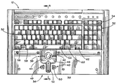
- FIG. 1 illustrates a perspective view of a device having a keyboard in accordance with the present technique
- FIG. 2 illustrates a top view of the keyboard of FIG. 1
- FIG. 3 is an enlarged partial top view of the keyboard of FIG. 1 illustrating one embodiment of a combination of a track ball mechanism and a scroll mechanism;
- FIG. 4 illustrates a cross-sectional view of the keyboard of FIG. 1 taken along line 4 — 4 ;
- FIG. 5 illustrates a cross-sectional view of the keyboard of FIG. 1 taken along line 5 — 5 ;
- FIG. 6 is an enlarged partial top view of the keyboard of FIG. 1 illustrating a second embodiment of a combination of a track ball mechanism and a scroll mechanism;
- FIG. 7 is an enlarged partial top view of the keyboard of FIG. 1 illustrating a third embodiment of a combination of a track ball mechanism and a scroll mechanism;
- FIG. 8 is an enlarged partial top view of the keyboard of FIG. 1 illustrating a fourth embodiment of a combination of a track ball mechanism and a scroll mechanism;
- FIG. 9 is an enlarged partial top view of the keyboard of FIG. 1 illustrating a fifth embodiment of a combination of a track ball mechanism and a scroll mechanism;
- FIG. 10 is an enlarged partial top view of the keyboard of FIG. 1 illustrating a sixth embodiment of a combination of a track ball mechanism and a scroll mechanism;
- FIG. 11 is an enlarged partial top view of the keyboard of FIG. 1 illustrating a seventh embodiment of a combination of a track ball mechanism and a scroll mechanism;
- FIG. 12 is an enlarged partial top view of the keyboard of FIG. 1 illustrating an eighth embodiment of a combination of a track ball mechanism and a scroll mechanism.
- FIG. 1 there is illustrated a perspective view of an exemplary device 10 having a keyboard 12 .
- the device 10 may be any of a variety of types, such as a personal computer, laptop, rack mountable device, etc.
- the device 10 is illustrated as having a display 14 .
- the display 14 may be coupled to the keyboard 12 by a hinge assembly 16 , so that the display 14 may be rotated to an open position when in use (as illustrated) or to a closed position when not in use.
- the device 10 is also illustrated as being a rack mountable device.
- the device 10 may include a slidable mounting assembly 18 , where a first portion 20 of the assembly 18 may be coupled to the device 10 and where a second portion 22 of the assembly 18 may be coupled to a rack 24 .
- the first portion 20 is adapted to slide relative to the second portion 22 to enable a user to extend the device 10 from the rack 24 during use and to store the device 10 in the rack 24 when not in use.
- the device 10 may further include a housing 26 , which may house various computing circuitry and components, such as a processor, memory, disk drives, communication devices, audio/video devices, and other suitable devices, such as a video controller for the display 14 and circuitry associated with the keyboard 12 .
- the keyboard 12 includes a standard portion 30 that typically resembles a standard “QWERTY” keyboard. Adjacent to the standard portion 30 , a numerical keypad 32 may be present. Above the standard portion 30 and/or the numerical keypad 32 , a row of function keys 34 may be present. Regardless of whether the numerical keypad 32 and the row of function keys 34 are present, a user will typically and primarily use the standard portion 30 of the keyboard 12 . Accordingly, a combination 36 of a track ball mechanism 38 and a scroll mechanism 40 is placed proximate the standard portion 30 of the keyboard 12 .
- the track ball mechanism 38 includes a track ball 42 , and activation buttons 44 and 46
- the scroll mechanism 40 includes a left arrow button 48 , a right arrow button 50 , and an up/down arrow button 52 .
- the track ball 42 may be rotated in any direction to place the cursor anywhere on the screen.
- one of the activation buttons 44 or 46 may be actuated to perform the desired function.
- the scroll buttons 48 , 50 , and 52 are provided to facilitate horizontal and vertical scrolling in a graphical user interface, such as in a program having horizontal and vertical scroll bars.
- the scroll buttons 48 and 50 can be depressed to scroll left and right, respectively, while the scroll button 52 can be depressed on an upper or lower portion for upward and downward scrolling, respectively.
- the combination 36 is advantageously placed close to the standard portion 30 of the keyboard 12 .
- the edge of the track ball 42 is located less than two inches, and advantageously less than one inch, from the space key 54 of the standard portion 30
- the scroll mechanism is located less than three inches, and advantageously less than two inches, from the space key 54 .
- the combination 36 of the track ball mechanism 38 and the scroll mechanism 40 is located in a central portion of the keyboard in this embodiment. With the combination 36 in this location, a user can access the track ball mechanism 38 and the scroll mechanism 40 with either hand without moving either hand from the standard portion of the keyboard.
- the combination 36 of the track ball mechanism 38 and the scroll mechanism 40 may be located directly beneath one of the user's hands, e.g., under the keys 56 and 58 or under the keys 60 and 62 . In either of these positions, a user can access the track ball mechanism 38 and the scroll mechanism 40 with one hand without moving either hand from the standard portion 30 of the keyboard 12 .
- the track ball mechanism 38 and the scroll mechanism 40 are advantageously placed in close proximity to one another.
- the track ball mechanism 38 and the scroll mechanism 40 may be arranged so that they essentially overlap or are integrated with one another.
- the up/down arrow button 52 is placed within recesses 64 and 66 in the activation buttons 44 and 46 , respectively.
- the scroll buttons 48 , 50 , and 52 themselves are relatively conventional.
- the scroll buttons 48 , 50 , and 52 are plastic and have a springy tactical touch.
- pressing the scroll buttons 48 , 50 , and 52 activates respective switches 72 , 74 , and 76 A and 76 B (up and down) on a printed circuit board 70 located beneath the scroll buttons 48 , 50 , and 52 .
- the printed circuit board 70 and the switches 72 , 74 , and 76 A and B are relatively conventional.
- FIG. 3 Although the discussion to this point has been primarily directed toward the particular embodiment illustrated in FIG. 3, it should be appreciated that various other embodiments are also contemplated. Some of these embodiments are illustrated in FIGS. 6-12 discussed below. However, those skilled in the art will understand that these exemplary embodiments are not limiting to the invention, as other embodiments not specifically illustrated may fall within the spirit and scope of the appended claims.
- the alternative combinations 36 A-G described below are also advantageously placed close to the standard portion 30 of the keyboard 12 .
- the combinations 36 A-G may be located less than two inches, and advantageously less than one inch, from the space key 54 of the standard portion 30 .
- this close proximity to the most-used standard portion 30 of the keyboard 12 facilitates access by a user. In fact, a user does not have to move their hands away from the standard portion 30 of the keyboard 12 to use either portion of the respective combinations 36 A-G.
- the combinations 36 A-G may be located in a central portion of the keyboard so that a user can access either portion of the respective combinations 36 A-G with either hand without moving either hand from the standard portion of the keyboard.
- the combinations 36 A-G may be located directly beneath one of the user's hands, e.g., under the keys 56 and 58 or under the keys 60 and 62 . In either of these positions, a user can access either portion of the respective combinations 36 A-G with one hand without moving either hand from the standard portion 30 of the keyboard 12 .
- FIG. 6 a second embodiment of a combination of a track ball mechanism and a scroll mechanism is illustrated.
- similar reference numerals will be used to designate elements similar to those discussed above. Accordingly, in this second embodiment, it should be noted that the combination 36 A of a track ball mechanism 38 A and a scroll mechanism 40 A is placed proximate the standard portion 30 of the keyboard 12 .
- the track ball mechanism 38 A includes a track ball 42 A, and activation buttons 44 A and 46 A
- the scroll mechanism 40 A includes a left arrow button 48 A, a right arrow button 50 A, an up arrow button 80 , and a down arrow button 82 .
- the track ball 42 A and the activation buttons 44 A and 46 A operate as previously described.
- the scroll buttons 48 A, 50 A, 80 , and 82 also operate in a manner similar to the first embodiment in that they are provided to facilitate horizontal and vertical scrolling in a graphical user interface, such as in a program having horizontal and vertical scroll bars.
- the scroll buttons 48 A and 50 A can be depressed to scroll left and right, respectively, while the scroll buttons 80 and 82 can be depressed to scroll up and down, respectively.
- the primary differences between the first and second embodiments reside in the use of more conventional buttons for the scroll buttons 48 A, 50 A, 80 , and 82 , and in the use of separate buttons 80 and 82 for scrolling up and down respectively.
- the track ball mechanism 38 A and the scroll mechanism 40 A are advantageously placed in close proximity to one another.
- the track ball mechanism 38 A and the scroll mechanism 40 A may be arranged so that they essentially overlap or are integrated with one another.
- the up arrow button 80 is placed within recesses 64 A and 66 A in the activation buttons 44 A and 46 A, respectively.
- FIG. 7 a third embodiment of a combination of a track ball mechanism and a scroll mechanism is illustrated. Again, for purposes of clarity, similar reference numerals will be used to designate elements similar to those discussed above. Accordingly, in this third embodiment, it should be noted that the combination 36 B of a track ball mechanism 38 B and a scroll mechanism 40 B is placed proximate the standard portion 30 of the keyboard 12 . Of course, unlike the first embodiment, this third embodiment has the positions of the track ball mechanism 38 B and the scroll mechanism 40 B switched, so that the scroll mechanism 40 B is closer to the standard portion 30 of the keyboard 12 than the track ball mechanism 38 B.
- the track ball mechanism 38 B includes a track ball 42 B, and activation buttons 44 B and 46 B
- the scroll mechanism 40 B includes a left arrow button 48 B, a right arrow button 50 B, and an up/down arrow button 52 B.
- the track ball 42 B and the activation buttons 44 B and 46 B operate as previously described.
- the scroll buttons 48 A, 50 A, and 52 B also operate in a manner as described with reference to the first embodiment.
- the track ball mechanism 38 B and the scroll mechanism 40 B are advantageously placed in close proximity to one another.
- the track ball mechanism 38 B and the scroll mechanism 40 B may be arranged so that they essentially overlap or are integrated with one another.
- the up/down arrow button 52 B is placed within recesses 64 B and 66 B in the activation buttons 44 B and 46 B, respectively.
- FIG. 8 a fourth embodiment of a combination of a track ball mechanism and a scroll mechanism is illustrated. Again, for purposes of clarity, similar reference numerals will be used to designate elements similar to those discussed above. Accordingly, in this fourth embodiment, it should be noted that the combination 36 C of a track ball mechanism 38 C and a scroll mechanism 40 C is placed proximate the standard portion 30 of the keyboard 12 .
- the track ball mechanism 38 C includes a track ball 42 C, and activation buttons 44 C and 46 C
- the scroll mechanism 40 C includes a left arrow button 48 C, a right arrow button 50 C, an up arrow button 80 C, and a down arrow button 82 C.
- the track ball 42 C and the activation buttons 44 C and 46 C operate as previously described.
- the scroll buttons 48 A, 50 A, 80 C, and 82 C operate as described with reference to FIG. 6 .
- the primary differences between the first and fourth embodiments reside in the use of separate buttons 80 C and 82 C for scrolling up and down, respectively.
- the scroll buttons 48 C, 50 C, 80 C, and 82 C are distributed around the track ball mechanism 38 C.
- the track ball mechanism 38 C and the scroll mechanism 40 C are advantageously placed in close proximity to one another.
- the track ball mechanism 38 C and the scroll mechanism 40 C may be arranged so that they are integrated with one another in the sense that the scroll buttons 48 C, 50 C, 80 C, and 82 C surround the track ball mechanism 38 C.
- FIG. 9 a fifth embodiment of a combination of a track ball mechanism and a scroll mechanism is illustrated. Again, for purposes of clarity, similar reference numerals will be used to designate elements similar to those discussed above. Accordingly, in this fifth embodiment, it should be noted that the combination 36 D of a track ball mechanism 38 D and a scroll mechanism 40 D is placed proximate the standard portion 30 of the keyboard 12 .
- the track ball mechanism 38 D includes a track ball 42 D, and activation buttons 44 D and 46 D
- the scroll mechanism 40 D includes a left arrow button 48 D, a right arrow button 50 D, and an up/down arrow button 52 D.
- the track ball 42 D and the activation buttons 44 D and 46 D operate as previously described.
- the scroll buttons 48 D, 50 D, and 52 D also operate in a manner as described in reference to the first embodiment.
- the primary difference between the first and fifth embodiments resides in the placement of the scroll mechanism 40 D.
- the track ball mechanism 38 D is centrally located beneath the space key 54 proximate the standard portion 30 of the keyboard 12 .
- the scroll mechanism 40 D is not located above, beneath, or around the track ball mechanism 38 D as in the previous embodiments. Instead, the scroll mechanism 40 D is placed to the right of the track ball mechanism 38 D, although it may be placed to the left as well. It should be noted that the scroll mechanism 40 D is not placed far from the track ball mechanism 38 D. Rather, like the first embodiment, to facilitate user access, the track ball mechanism 38 D and the scroll mechanism 40 D are advantageously placed in close proximity to one another, e.g, less than one inch of separation.
- both mechanisms 38 D and 40 D are not integrated with one another.
- both mechanisms 38 D and 40 D may be located quite close to the standard portion 30 of the keyboard 12 , e.g., less than one inch from the space key 54 .
- a user can easily access both mechanisms 38 D and 40 D without removing either hand from the standard portion 30 of the keyboard 12 .
- FIG. 10 a sixth embodiment of a combination of a track ball mechanism and a scroll mechanism is illustrated. Again, for purposes of clarity, similar reference numerals will be used to designate elements similar to those discussed above. Accordingly, in this sixth embodiment, it should be noted that the combination 36 E of a track ball mechanism 38 E and a scroll mechanism 40 E is placed proximate the standard portion 30 of the keyboard 12 .
- the track ball mechanism 38 E includes a track ball 42 E and activation buttons 44 E and 46 E.
- the track ball 42 E and the activation buttons 44 E and 46 E operate as previously described.
- the scroll mechanism 40 E includes a left arrow button 48 E and a right arrow button 50 E as previously described.
- the scroll mechanism 40 E includes a wheel 84 in place of an up/down arrow button.
- the track ball mechanism 38 E and the scroll mechanism 40 E are advantageously placed in close proximity to one another.
- the track ball mechanism 38 E and the scroll mechanism 40 E may be arranged so that they essentially overlap or are integrated with one another.
- the wheel 84 is placed within recesses 64 E and 66 E in the activation buttons 44 E and 46 E, respectively.
- FIG. 11 a seventh embodiment of a combination of a track ball mechanism and a scroll mechanism is illustrated. Again, for purposes of clarity, similar reference numerals will be used to designate elements similar to those discussed above. Accordingly, in this seventh embodiment, it should be noted that the combination 36 F of a track ball mechanism 38 F and a scroll mechanism 40 F is placed proximate the standard portion 30 of the keyboard 12 .
- the track ball mechanism 38 F includes a track ball 42 F and activation buttons 44 F and 46 F.
- the track ball 42 F and the activation buttons 44 F and 46 F operate as previously described.
- the scroll mechanism 40 F does not include any arrow buttons.
- the scroll mechanism 40 F includes a joystick 86 that operates within a guide 88 . By moving the joystick 86 in one of the four directions within the guide 88 , the screen may be scrolled upwardly, downwardly, to the left, or to the right.
- the track ball mechanism 38 F and the scroll mechanism 40 F are advantageously placed in close proximity to one another.
- the track ball mechanism 38 F and the scroll mechanism 40 F may be arranged so that they essentially overlap or are integrated with one another.
- the guide 88 is placed within recesses 64 F and 66 F in the activation buttons 44 F and 46 F, respectively.
- FIG. 12 an eighth embodiment of a combination of a track ball mechanism and a scroll mechanism is illustrated. Again, for purposes of clarity, similar reference numerals will be used to designate elements similar to those discussed above. Accordingly, in this second embodiment, it should be noted that the combination 36 G of a track ball mechanism 38 G and a scroll mechanism 40 G is placed proximate the standard portion 30 of the keyboard 12 .
- the track ball mechanism 38 G includes a track ball 42 G and activation buttons 44 G and 46 G.
- the track ball 42 G and the activation buttons 44 G and 46 G operate as previously described.
- the scroll mechanism 40 G does not include separate arrow buttons.
- the scroll mechanism 40 G includes a single button 90 .
- the button 90 has four legs 92 , 94 , 96 , and 98 which correspond to the up, right, down, and left arrows, respectively.
- the button 90 is gimbaled at its center so that a user can press any of the four legs 92 , 94 , 96 , and 98 to scroll the screen upwardly, downwardly, to the left, or to the right.
- the track ball mechanism 38 G and the scroll mechanism 40 G are advantageously placed in close proximity to one another.
- the track ball mechanism 38 G and the scroll mechanism 40 G may be arranged so that they essentially overlap or are integrated with one another.
- the leg 92 of the button 90 is placed within recesses 64 G and 66 G in the activation buttons 44 G and 46 G, respectively.
Landscapes
- Engineering & Computer Science (AREA)
- Theoretical Computer Science (AREA)
- General Engineering & Computer Science (AREA)
- Physics & Mathematics (AREA)
- Computer Hardware Design (AREA)
- Human Computer Interaction (AREA)
- General Physics & Mathematics (AREA)
- Mathematical Physics (AREA)
- Position Input By Displaying (AREA)
Abstract
Description
Claims (43)
Priority Applications (1)
| Application Number | Priority Date | Filing Date | Title |
|---|---|---|---|
| US09/873,778 US6830394B2 (en) | 2001-06-04 | 2001-06-04 | Keyboard having a track ball mechanism and a scroll mechanism |
Applications Claiming Priority (1)
| Application Number | Priority Date | Filing Date | Title |
|---|---|---|---|
| US09/873,778 US6830394B2 (en) | 2001-06-04 | 2001-06-04 | Keyboard having a track ball mechanism and a scroll mechanism |
Publications (2)
| Publication Number | Publication Date |
|---|---|
| US20020181991A1 US20020181991A1 (en) | 2002-12-05 |
| US6830394B2 true US6830394B2 (en) | 2004-12-14 |
Family
ID=25362294
Family Applications (1)
| Application Number | Title | Priority Date | Filing Date |
|---|---|---|---|
| US09/873,778 Expired - Lifetime US6830394B2 (en) | 2001-06-04 | 2001-06-04 | Keyboard having a track ball mechanism and a scroll mechanism |
Country Status (1)
| Country | Link |
|---|---|
| US (1) | US6830394B2 (en) |
Cited By (4)
| Publication number | Priority date | Publication date | Assignee | Title |
|---|---|---|---|---|
| US20030122783A1 (en) * | 2001-12-28 | 2003-07-03 | Green Carl I. | Horizontal wheel user input device |
| US20040041790A1 (en) * | 2002-06-14 | 2004-03-04 | Logitech Europe S.A. | Button simulating rotation of input device roller |
| US20060152480A1 (en) * | 2005-01-13 | 2006-07-13 | Eaton Corporation | Handheld electronic device, user interface and method employing an input wheel disposed at about a 45 degree angle |
| USD687831S1 (en) * | 2011-02-12 | 2013-08-13 | Samsung Electronics Co., Ltd. | Notebook computer |
Families Citing this family (1)
| Publication number | Priority date | Publication date | Assignee | Title |
|---|---|---|---|---|
| TWM253842U (en) * | 2003-12-24 | 2004-12-21 | Ruei-Hung Chen | Keyboard with device for mouse control |
Citations (15)
| Publication number | Priority date | Publication date | Assignee | Title |
|---|---|---|---|---|
| USD291574S (en) | 1985-01-14 | 1987-08-25 | Wico Distribution Company, L.P. | Keyboard including trackball |
| US5122654A (en) | 1990-05-25 | 1992-06-16 | Logitech, Inc. | Ergonomic thumb-actuated trackball combined with control switches |
| USD350126S (en) | 1993-01-19 | 1994-08-30 | Ouanta Computer Inc. | Computer keyboard with built-in trackball |
| USD363277S (en) | 1993-12-17 | 1995-10-17 | Silitek Corporation | Keyboard with a trackball |
| USD365335S (en) | 1994-08-25 | 1995-12-19 | Dell Usa, L.P. | Portable computer with trackball below keyboard |
| USD366256S (en) | 1994-12-06 | 1996-01-16 | Digital Equipment Corporation | Keyboard with trackball pointing device |
| US5808922A (en) * | 1996-07-23 | 1998-09-15 | Martinez; Daniel L. | Integrated keyboard |
| US5841076A (en) * | 1993-10-14 | 1998-11-24 | Ascom Hasler Mailing Systems, Inc. | Electronic scale system with programmable function keys |
| US6016139A (en) * | 1992-11-05 | 2000-01-18 | Sony Corporation | Motion picture reproducing and recording/reproduction apparatus |
| US6043809A (en) | 1997-09-23 | 2000-03-28 | Compaq Computer Corporation | Computer keyboard scroll bar control |
| US6047196A (en) * | 1995-11-24 | 2000-04-04 | Nokia Mobile Phones, Ltd. | Communication device with two modes of operation |
| US6075518A (en) * | 1997-07-15 | 2000-06-13 | Gateway 2000, Inc. | Rotational X-axis pointing device |
| US6091404A (en) | 1993-12-07 | 2000-07-18 | Hong; Seung Seog | Trackball for a portable computer |
| US6351225B1 (en) * | 1999-08-05 | 2002-02-26 | Enrique I. Moreno | Multimedia PC keyboard extended with music control keys |
| US6392634B1 (en) * | 1993-07-08 | 2002-05-21 | Dell Usa, L.P. | Portable computer having reversible trackball/mouse device |
-
2001
- 2001-06-04 US US09/873,778 patent/US6830394B2/en not_active Expired - Lifetime
Patent Citations (15)
| Publication number | Priority date | Publication date | Assignee | Title |
|---|---|---|---|---|
| USD291574S (en) | 1985-01-14 | 1987-08-25 | Wico Distribution Company, L.P. | Keyboard including trackball |
| US5122654A (en) | 1990-05-25 | 1992-06-16 | Logitech, Inc. | Ergonomic thumb-actuated trackball combined with control switches |
| US6016139A (en) * | 1992-11-05 | 2000-01-18 | Sony Corporation | Motion picture reproducing and recording/reproduction apparatus |
| USD350126S (en) | 1993-01-19 | 1994-08-30 | Ouanta Computer Inc. | Computer keyboard with built-in trackball |
| US6392634B1 (en) * | 1993-07-08 | 2002-05-21 | Dell Usa, L.P. | Portable computer having reversible trackball/mouse device |
| US5841076A (en) * | 1993-10-14 | 1998-11-24 | Ascom Hasler Mailing Systems, Inc. | Electronic scale system with programmable function keys |
| US6091404A (en) | 1993-12-07 | 2000-07-18 | Hong; Seung Seog | Trackball for a portable computer |
| USD363277S (en) | 1993-12-17 | 1995-10-17 | Silitek Corporation | Keyboard with a trackball |
| USD365335S (en) | 1994-08-25 | 1995-12-19 | Dell Usa, L.P. | Portable computer with trackball below keyboard |
| USD366256S (en) | 1994-12-06 | 1996-01-16 | Digital Equipment Corporation | Keyboard with trackball pointing device |
| US6047196A (en) * | 1995-11-24 | 2000-04-04 | Nokia Mobile Phones, Ltd. | Communication device with two modes of operation |
| US5808922A (en) * | 1996-07-23 | 1998-09-15 | Martinez; Daniel L. | Integrated keyboard |
| US6075518A (en) * | 1997-07-15 | 2000-06-13 | Gateway 2000, Inc. | Rotational X-axis pointing device |
| US6043809A (en) | 1997-09-23 | 2000-03-28 | Compaq Computer Corporation | Computer keyboard scroll bar control |
| US6351225B1 (en) * | 1999-08-05 | 2002-02-26 | Enrique I. Moreno | Multimedia PC keyboard extended with music control keys |
Cited By (5)
| Publication number | Priority date | Publication date | Assignee | Title |
|---|---|---|---|---|
| US20030122783A1 (en) * | 2001-12-28 | 2003-07-03 | Green Carl I. | Horizontal wheel user input device |
| US20040041790A1 (en) * | 2002-06-14 | 2004-03-04 | Logitech Europe S.A. | Button simulating rotation of input device roller |
| US7075526B2 (en) * | 2002-06-14 | 2006-07-11 | Logitech Europe S.A. | Button simulating rotation of input device roller |
| US20060152480A1 (en) * | 2005-01-13 | 2006-07-13 | Eaton Corporation | Handheld electronic device, user interface and method employing an input wheel disposed at about a 45 degree angle |
| USD687831S1 (en) * | 2011-02-12 | 2013-08-13 | Samsung Electronics Co., Ltd. | Notebook computer |
Also Published As
| Publication number | Publication date |
|---|---|
| US20020181991A1 (en) | 2002-12-05 |
Similar Documents
| Publication | Publication Date | Title |
|---|---|---|
| US8514186B2 (en) | Handheld electronic device and operation method thereof | |
| US10552037B2 (en) | Software keyboard input method for realizing composite key on electronic device screen with precise and ambiguous input | |
| US6587094B2 (en) | Two-sided input device for a computer-related apparatus | |
| US9116551B2 (en) | Method for quickly inputting correlative word | |
| US20100026626A1 (en) | Efficient keyboards | |
| JP4046685B2 (en) | Modular, ergonomic, multifunctional, multi-layer, general purpose standard keyboard | |
| JP4909355B2 (en) | Character input device | |
| US20040196268A1 (en) | Input module and operating method thereof | |
| US20110227834A1 (en) | Electronic device with touch keypad | |
| JP2005531064A (en) | keyboard | |
| US8154429B2 (en) | Keyboard device | |
| US6830394B2 (en) | Keyboard having a track ball mechanism and a scroll mechanism | |
| JP2008059568A (en) | Character input device and character input method using numeric keypad | |
| BRPI0617061A2 (en) | portable keyboard | |
| KR101358357B1 (en) | Remote control for touch pad | |
| US20060279550A1 (en) | Integrally formed touchpad module | |
| JP4917114B2 (en) | Trackball socket for handheld wireless communication devices | |
| US20090002320A1 (en) | Keyboard With Surface for Computer Mouse Operation and Moveable Numeric Keypad | |
| US6616358B1 (en) | Keyboard structure alteration method | |
| US6431776B1 (en) | Compact keyboard | |
| KR102815266B1 (en) | Mini keyboard for customized shortcut key usage | |
| US6398437B1 (en) | Keyboard and computer | |
| US20040090422A1 (en) | Keyboard | |
| KR200329499Y1 (en) | Apparatus for inputting character and numeral on communication device | |
| CN101118475A (en) | Reduced keyboard with composite keys |
Legal Events
| Date | Code | Title | Description |
|---|---|---|---|
| AS | Assignment |
Owner name: COMPAQ INFORMATION TECHNOLOGIES GROUP, LP, TEXAS Free format text: ASSIGNMENT OF ASSIGNORS INTEREST;ASSIGNORS:FELCMAN, CHRIS;EICHBERGER, DAVID P.;LANDRUM, GARY;AND OTHERS;REEL/FRAME:012261/0204;SIGNING DATES FROM 20010910 TO 20010923 |
|
| AS | Assignment |
Owner name: HEWLETT-PACKARD DEVELOPMENT COMPANY, L.P., TEXAS Free format text: CHANGE OF NAME;ASSIGNOR:COMPAQ INFORMATION TECHNOLOGIES GROUP LP;REEL/FRAME:014628/0103 Effective date: 20021001 |
|
| STCF | Information on status: patent grant |
Free format text: PATENTED CASE |
|
| FPAY | Fee payment |
Year of fee payment: 4 |
|
| REMI | Maintenance fee reminder mailed | ||
| FPAY | Fee payment |
Year of fee payment: 8 |
|
| AS | Assignment |
Owner name: HEWLETT PACKARD ENTERPRISE DEVELOPMENT LP, TEXAS Free format text: ASSIGNMENT OF ASSIGNORS INTEREST;ASSIGNOR:HEWLETT-PACKARD DEVELOPMENT COMPANY, L.P.;REEL/FRAME:037079/0001 Effective date: 20151027 |
|
| FPAY | Fee payment |
Year of fee payment: 12 |
|
| AS | Assignment |
Owner name: OT PATENT ESCROW, LLC, ILLINOIS Free format text: PATENT ASSIGNMENT, SECURITY INTEREST, AND LIEN AGREEMENT;ASSIGNORS:HEWLETT PACKARD ENTERPRISE DEVELOPMENT LP;HEWLETT PACKARD ENTERPRISE COMPANY;REEL/FRAME:055269/0001 Effective date: 20210115 |
|
| AS | Assignment |
Owner name: VALTRUS INNOVATIONS LIMITED, IRELAND Free format text: ASSIGNMENT OF ASSIGNORS INTEREST;ASSIGNOR:OT PATENT ESCROW, LLC;REEL/FRAME:055403/0001 Effective date: 20210201 |