US683034A - Pressure-regulator for gas-generators. - Google Patents
Pressure-regulator for gas-generators. Download PDFInfo
- Publication number
- US683034A US683034A US3285200A US1900032852A US683034A US 683034 A US683034 A US 683034A US 3285200 A US3285200 A US 3285200A US 1900032852 A US1900032852 A US 1900032852A US 683034 A US683034 A US 683034A
- Authority
- US
- United States
- Prior art keywords
- gas
- bell
- generator
- regulator
- engine
- Prior art date
- Legal status (The legal status is an assumption and is not a legal conclusion. Google has not performed a legal analysis and makes no representation as to the accuracy of the status listed.)
- Expired - Lifetime
Links
- XLYOFNOQVPJJNP-UHFFFAOYSA-N water Substances O XLYOFNOQVPJJNP-UHFFFAOYSA-N 0.000 description 13
- 238000009434 installation Methods 0.000 description 6
- 206010010254 Concussion Diseases 0.000 description 4
- 230000009514 concussion Effects 0.000 description 4
- 238000013459 approach Methods 0.000 description 2
- 238000004140 cleaning Methods 0.000 description 2
- 238000010276 construction Methods 0.000 description 2
- 230000003292 diminished effect Effects 0.000 description 2
- 238000004519 manufacturing process Methods 0.000 description 2
- 241000876852 Scorias Species 0.000 description 1
- 230000006835 compression Effects 0.000 description 1
- 238000007906 compression Methods 0.000 description 1
- 239000000428 dust Substances 0.000 description 1
- 230000000694 effects Effects 0.000 description 1
- 239000000446 fuel Substances 0.000 description 1
- 230000004048 modification Effects 0.000 description 1
- 238000012986 modification Methods 0.000 description 1
- 230000010355 oscillation Effects 0.000 description 1
Images

Classifications
-
- C—CHEMISTRY; METALLURGY
- C10—PETROLEUM, GAS OR COKE INDUSTRIES; TECHNICAL GASES CONTAINING CARBON MONOXIDE; FUELS; LUBRICANTS; PEAT
- C10J—PRODUCTION OF PRODUCER GAS, WATER-GAS, SYNTHESIS GAS FROM SOLID CARBONACEOUS MATERIAL, OR MIXTURES CONTAINING THESE GASES; CARBURETTING AIR OR OTHER GASES
- C10J3/00—Production of combustible gases containing carbon monoxide from solid carbonaceous fuels
- C10J3/72—Other features
Definitions
- WITNESS'ES INVEN TOR Q. HE/ IVR/GH q mnas W VQm/UV WW HIS HTTORNEYJ,
- the present invention relates to a pressureregulator for a gas-generator which is connected in such manner with the gas-engine that it is worked by the suction of the engine, so that only so much gas is produced as is required at the time by the engine.
- the present invention consists in constructing the pressure-regulator so that the buoyancy of the bell changes according to the resistance offered to the flow of gas.
- the bell canbe provided with two floats of different sizes, of which the larger one is always under water, and therefore always has the same buoyancy, while the smaller float projects above the water, so that in proportion as the bell, with the increase of resistance to the flow of gas, dips deeper into the water the smaller float also dips under water, and thus correspondingly increases the buoyancy of the bell, or thesame result may be accomplished by providing the bell with an air-box under water, in which the buoyancy of the bell can be changed as desired by forcing air into the same or letting air out of the same.
- a pressure-regulator of the first-named kind is represented in the sectional view
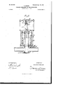
- FIG. 1 is a vertical section of the modification mentioned above.
- Fig. 1 the upper or gas space of the generator a is connected, by means of the piping b, with the gas-engine, which is not shown in the drawing.
- the branch tube f passes upward and opens into the bell o in the water vessel 9.
- the bell is guided vertically by means of the rod h passing through the cross-bar Z, mounted on the Vessel g.
- the lower end of the rod works in the guide f at the upper end of the branchf.
- the hell 0 is provided with two floats, of which the larger lower float cl is always under water, even when the bell is at its highest point, and therefore always has the same buoyant action on the bell.
- the smaller float e is placed above the float d and projects far above the water.
- This float e is for the purpose of increasing the buoyancy when the bell is drawn downward by the suction to a lower position.
- the large float d has a uniform buoyancy which corresponds to the sucking action of a column of water of forty millimeters, as may be required with a normal working of the installation, while after the obstruction of the generator by sooria or the obstruction of a cleaner a pressure of sixty millimeters might be necessary, then the hell 0 would be drawn downward to oscillate in a correspondingly lower position, in which the smaller float calso adds so much buoyancy as to compensate for the increase in the suction.
- two springs i and bare provided on the guiding-rod h of the bell In order that it may be possible to further regulate the sucking action on the bell 0, two springs i and bare provided on the guiding-rod h of the bell.
- the upper spring '6 bears at the lower end 5 against the cross-bar l and at the upper end against a stop n, adjustable on the rod h.
- the spring 76 bears at its lower end against the bell c and at its upper end against a stop m, adjust-able on the threaded tubular rod on, which is affixed to the cross-bar Z. If the suction should have to be increased, for instance, in order to supply several gas-engines from the same generator, the upper spring 1' would be put at greater tension and the lower spring 7c correspondingly loosened. These two springs further serve to lessen the concussions arising from violent upward and downward movements of the bell.
- I provide at the lower part of the float-bell c the air-box d, open below. Into this there enters from below the air-tube m, which is provided with a cock m The air-box is provided with a tuben, extending upward. Into this the air-tube m extends when the float-bell c is at its lowest position. On placing the float-bell into the water vessel 9 the air-box d, according to the height at which the water stands, will become filled to a certain height with water.
- a single spring 76 is provided in this construction instead of two springs, as in the first case.
- This spring embraces a box 0, which is guided at its upper end in the guide 19 of the cross-bar l and is provided with a disk g, which bears on the upper end of the spring The lower end of the spring it rests on a disk T, which is carried'by the arms 8, fixed to the bar a.
- a suction pressure-regulator for generator and gas-engine installations the combination of a gas-generator and the piping connecting the generator to the engine with a floating bell open to said piping and means for varying the buoyancy of the bell according to the varying resistance offered to the passage of the gas, whereby only so much gas is produced in the generator as is required by the engine, substantially as described.
Landscapes
- Chemical & Material Sciences (AREA)
- Engineering & Computer Science (AREA)
- Combustion & Propulsion (AREA)
- Oil, Petroleum & Natural Gas (AREA)
- Organic Chemistry (AREA)
- Engine Equipment That Uses Special Cycles (AREA)
Description
Nu. 683,034. Patented Sept. 24, l90l. H. GERDES.
PRESSURE REGULATOR FOR GAS GENERATORS.
(Application filed Oct. 12, 1900.)
2 Sheets-Sheet (No Model.)
WITNESS'ES: INVEN TOR Q. HE/ IVR/GH q mnas W VQm/UV WW HIS HTTORNEYJ,
THE NORRIS Pma s co mm'ourucu wAsnmcrorg. n. cy
No. 683,034. Patented Sept. 24, l90l. H. GERDES.
PRESSURE REGULATOR FOR GAS GENERATORS.
(Appliuation filed Oct. 12, 1900.) (No Model.) I 2 Sheets-Sheet 2.
WIT'IVE ass 5. Mrs/Wok Tu; uomzls 95mm 00,. PNOTO-LITHUY, WASHINGTON, 0. c.
UNITED STATES PATENT OFFIC HEINRICH GERDES, OF BERLIN, GERMANY, ASSIGNOR TO THE FIRM OF JULIUS PINTSOH, OF SAME PLACE.
PRESSURE-REGULATOR FOR GAS-G EN E,RATORS..
SPECIFICATION forming part of Letters Patent No. 683,034, dated September 24, 1901.
Application filed October 12, 1900. Serial No. 32,852. (No model.
To all whom it may concern:
Be it known that I, HEINRICH GERDEs, a sub ject of the Emperor of Germany, residing in Berlin, Germany, have invented an Improved Pressure-Regulator for Generator and Gas- Engine Installations, of which the following is a specification. Y
The present invention relates to a pressureregulator for a gas-generator which is connected in such manner with the gas-engine that it is worked by the suction of the engine, so that only so much gas is produced as is required at the time by the engine.
In order to make the production of gas as uniform as possible, it has been suggested to interpose in the piping between the generator and the gas-engine a bell which dips in water and to which a definite upthrust or buoyancy is given by means of a counterweight; but such a pressure-regulator is not suitable for practical working, because the conditions of the production and supply of gas change as time goes on. As the fuel in the generator is not always placed in uniformly thick layers, the generator becomes more and more lined with scoria the longer it is used, so that the resistance opposed to the passage of the air or gas changes, and this resistance is also further changed by the fact that in the cleaning apparatus great quantities of dust are deposited, with the effect of making the passage of the gas more diflicult.
Now the present invention consists in constructing the pressure-regulator so that the buoyancy of the bell changes according to the resistance offered to the flow of gas. For this purpose the bell canbe provided with two floats of different sizes, of which the larger one is always under water, and therefore always has the same buoyancy, while the smaller float projects above the water, so that in proportion as the bell, with the increase of resistance to the flow of gas, dips deeper into the water the smaller float also dips under water, and thus correspondingly increases the buoyancy of the bell, or thesame result may be accomplished by providing the bell with an air-box under water, in which the buoyancy of the bell can be changed as desired by forcing air into the same or letting air out of the same.
A pressure-regulator of the first-named kind is represented in the sectional view,
Figure 1, of the accompanying drawings in combination witha generator; but the gas-engine and the cleaning apparatus are omitted. Fig. 2 is a vertical section of the modification mentioned above.
In Fig. 1 the upper or gas space of the generator a is connected, by means of the piping b, with the gas-engine, which is not shown in the drawing. From this tube 1) the branch tube f passes upward and opens into the bell o in the water vessel 9. The bell is guided vertically by means of the rod h passing through the cross-bar Z, mounted on the Vessel g. The lower end of the rod works in the guide f at the upper end of the branchf. The hell 0 is provided with two floats, of which the larger lower float cl is always under water, even when the bell is at its highest point, and therefore always has the same buoyant action on the bell. The smaller float e is placed above the float d and projects far above the water. This float e is for the purpose of increasing the buoyancy when the bell is drawn downward by the suction to a lower position. For instance, if the large float dhas a uniform buoyancy which corresponds to the sucking action of a column of water of forty millimeters, as may be required with a normal working of the installation, while after the obstruction of the generator by sooria or the obstruction of a cleaner a pressure of sixty millimeters might be necessary, then the hell 0 would be drawn downward to oscillate in a correspondingly lower position, in which the smaller float calso adds so much buoyancy as to compensate for the increase in the suction. In order that it may be possible to further regulate the sucking action on the bell 0, two springs i and bare provided on the guiding-rod h of the bell.
The upper spring '6 bears at the lower end 5 against the cross-bar l and at the upper end against a stop n, adjustable on the rod h. The spring 76 bears at its lower end against the bell c and at its upper end against a stop m, adjust-able on the threaded tubular rod on, which is affixed to the cross-bar Z. If the suction should have to be increased, for instance, in order to supply several gas-engines from the same generator, the upper spring 1' would be put at greater tension and the lower spring 7c correspondingly loosened. These two springs further serve to lessen the concussions arising from violent upward and downward movements of the bell.
Referring to the modified form of regulator represented in Fig. 2, I provide at the lower part of the float-bell c the air-box d, open below. Into this there enters from below the air-tube m, which is provided with a cock m The air-box is provided with a tuben, extending upward. Into this the air-tube m extends when the float-bell c is at its lowest position. On placing the float-bell into the water vessel 9 the air-box d, according to the height at which the water stands, will become filled to a certain height with water. Now according as air is pressed into the box d through the tube mor let out of the same the quantity of air in the box is increased or diminished, and thereby the buoyancy of the bell may be correspondingly increased or diminished. To lessen the concussions, only a single spring 76 is provided in this construction instead of two springs, as in the first case. This spring embraces a box 0, which is guided at its upper end in the guide 19 of the cross-bar l and is provided with a disk g, which bears on the upper end of the spring The lower end of the spring it rests on a disk T, which is carried'by the arms 8, fixed to the bar a. When the hell 0' approaches its lowest position, the head t of the guiding-rod It bears against the bottom of the box 0, as represented in full lines in Fig. 2, so that the disk q presses from above against the spring 70 and the latter is compressed. The downward movement of the bell is received by the spring in this manner. On the other hand, when the bell in its upward movement approaches its highest position the nut 11, on the rod h, serving as a stop, strikes against the lower disk 7' and lifts the same. In this case the compression of the spring It will take place when the upper shell q is lifted so far that it comes to bear against the cross-bar Z. Thus the one spring serves to lessen the concussions at both the downward and the upward movements of the bell. In both constructions described it will be seen that the generator and the regulator are both worked under and by the suction of the gas-engine, so that through the regulator only so much gas is sucked or drawn from the generator as by the engine from the regulator and the connecting-tubes, and, in other words, only so much gas is produced in the generator as is required at the time by the engine.
I claim as my invention-- 1. In a suction pressure-regulator for generator and gas-engine installations, the combination of a gas-generator and the piping connecting the generator to the engine with a floating bell open to said piping and means for varying the buoyancy of the bell according to the varying resistance offered to the passage of the gas, whereby only so much gas is produced in the generator as is required by the engine, substantially as described.
2. In a suction pressure-regulator for generator and gas-engine installations, the combination of a gasgenerator and the piping connecting the generator to the engine with a floating bell open to said piping and provided with means for automatically varying the buoyancy of the bell according to the varying resistance offered to the passage of the gas, whereby only so much gas is produced in the generator as is required by the engine, substantially as described.
3. In a suction pressure-regulator for generator and gas-engine installations, the combination of the piping connecting the generator and engine with a floating bell open to said piping and spring means acting on the float against both its upward and downward movements to diminish concussions in its oscillations, substantially as described.
4. In a suction pressure-regulator for generator and gas-engine installations, the combination of the piping connecting the generator and engine with a floating bell open to said piping, means for varying the buoyancy of the bell and two adjustable springs acting upon said bell, substantially as and for the purpose described.
In testimony whereof I have signed my name to this specification in the presence of two subscribing witnesses.
- HEINRICH GERDES.
Witnesses:
WOLDEMAR HAUPT, HENRY HASPER.
Priority Applications (1)
| Application Number | Priority Date | Filing Date | Title |
|---|---|---|---|
| US3285200A US683034A (en) | 1900-10-12 | 1900-10-12 | Pressure-regulator for gas-generators. |
Applications Claiming Priority (1)
| Application Number | Priority Date | Filing Date | Title |
|---|---|---|---|
| US3285200A US683034A (en) | 1900-10-12 | 1900-10-12 | Pressure-regulator for gas-generators. |
Publications (1)
| Publication Number | Publication Date |
|---|---|
| US683034A true US683034A (en) | 1901-09-24 |
Family
ID=2751577
Family Applications (1)
| Application Number | Title | Priority Date | Filing Date |
|---|---|---|---|
| US3285200A Expired - Lifetime US683034A (en) | 1900-10-12 | 1900-10-12 | Pressure-regulator for gas-generators. |
Country Status (1)
| Country | Link |
|---|---|
| US (1) | US683034A (en) |
-
1900
- 1900-10-12 US US3285200A patent/US683034A/en not_active Expired - Lifetime
Similar Documents
| Publication | Publication Date | Title |
|---|---|---|
| US683034A (en) | Pressure-regulator for gas-generators. | |
| US597249A (en) | Peter smith | |
| US1100601A (en) | Feed-water regulator. | |
| US1840859A (en) | Carbonating apparatus | |
| US1943903A (en) | Carbonating apparatus | |
| US718361A (en) | Apparatus for carbureting air. | |
| US678194A (en) | Carbureter. | |
| US1062981A (en) | Carbureting apparatus. | |
| US671052A (en) | Carbureter. | |
| US624963A (en) | Feed-water purifier and boiler-skimmer | |
| US983255A (en) | Automatic regulator for acetylene-gas generators. | |
| US1004629A (en) | Apparatus for controlling the flow of liquids or gases. | |
| US799947A (en) | Feed-water regulator. | |
| US1202379A (en) | Water-measuring apparatus. | |
| US843778A (en) | Carbonator. | |
| US969257A (en) | Steam regenerative accumulator. | |
| US666204A (en) | Acetylene-gas generator. | |
| US777545A (en) | Gas-generating apparatus. | |
| US340454A (en) | Gas-regulator | |
| US672947A (en) | Gas-generator. | |
| US593115A (en) | normand | |
| US737593A (en) | Gas regulating and saving apparatus. | |
| US838022A (en) | Acetylene-gas generator. | |
| US2062095A (en) | Control mechanism | |
| US697303A (en) | Ram. |