US6830255B2 - Scooter with a shock-absorbing unit - Google Patents
Scooter with a shock-absorbing unit Download PDFInfo
- Publication number
- US6830255B2 US6830255B2 US10/342,214 US34221403A US6830255B2 US 6830255 B2 US6830255 B2 US 6830255B2 US 34221403 A US34221403 A US 34221403A US 6830255 B2 US6830255 B2 US 6830255B2
- Authority
- US
- United States
- Prior art keywords
- frame part
- absorber
- coupling end
- scooter
- mounting
- Prior art date
- Legal status (The legal status is an assumption and is not a legal conclusion. Google has not performed a legal analysis and makes no representation as to the accuracy of the status listed.)
- Expired - Fee Related, expires
Links
Images


Classifications
-
- B—PERFORMING OPERATIONS; TRANSPORTING
- B62—LAND VEHICLES FOR TRAVELLING OTHERWISE THAN ON RAILS
- B62K—CYCLES; CYCLE FRAMES; CYCLE STEERING DEVICES; RIDER-OPERATED TERMINAL CONTROLS SPECIALLY ADAPTED FOR CYCLES; CYCLE AXLE SUSPENSIONS; CYCLE SIDE-CARS, FORECARS, OR THE LIKE
- B62K3/00—Bicycles
- B62K3/002—Bicycles without a seat, i.e. the rider operating the vehicle in a standing position, e.g. non-motorized scooters; non-motorized scooters with skis or runners
Definitions
- the present invention relates to a scooter, more particularly to a scooter with a shock-absorbing unit.
- a conventional scooter generally includes a front frame body with a front wheel, and a rear frame body with a rear wheel.
- a shock-absorbing member is disposed between and interconnects the front and rear frame bodies for absorbing shocks acting on the conventional scooter.
- the object of this invention is to provide a scooter having front and rear frame parts coupled pivotally through a pivot unit, and equipped with two shock-absorbers which cooperate with the pivot unit to provide smooth absorbing actions of the shock-absorbers.
- a scooter includes: a front frame part having a horizontally extending base with a rear coupling end, and a front absorber-mounting member that is disposed adjacent to the rear coupling end and that projects upwardly from the base; a front wheel connected rotatably to the front frame part; a pivot unit; a rear frame part having a front coupling end pivoted to the rear coupling end of the front frame part through the pivot unit so as to permit turning of the rear frame part relative to the front frame part, the rear frame part further having spaced apart left and right wheel-mounting arms extending rearwardly from the front coupling end in a transverse direction relative to the pivot unit, and a rear absorber-mounting member that is disposed adjacent to the front coupling end and that is fixed to and that extends upwardly from the wheel-mounting arms; a rear wheel connected rotatably to the wheel-mounting arms of the rear frame part; and left and right shock-absorbers having front ends pivoted to the front absorber-mounting member,
- FIG. 1 is a schematic side view of the preferred embodiment of a scooter according to the present invention.
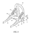
- FIG. 2 is a fragmentary perspective view illustrating how left and right shock-absorbers interconnect front and rear frame parts of the preferred embodiment
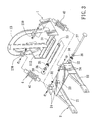
- FIG. 3 is a fragmentary exploded perspective view of the preferred embodiment
- FIG. 4 is a fragmentary sectional view of a pivot unit of the preferred embodiment, illustrating how the front and rear frame parts are connected pivotally by the pivot unit;
- FIG. 5 is a schematic side view of the preferred embodiment, showing how the rear frame part reacts relative to the front frame part upon encountering a shock;
- FIG. 6 is a fragmentary schematic view illustrating how a handle of the preferred embodiment is adjusted relative to a handle-mounting seat
- FIG. 7 is a fragmentary sectional view illustrating how the handle of the preferred embodiment is locked by a quick-release locking device to prevent position change of the handle relative to the handle-mounting seat;
- FIG. 8 is a sectional view of a front wheel employed in the preferred embodiment.
- FIG. 9 is a sectional view of a rear wheel employed in the preferred embodiment.
- the preferred embodiment of a scooter according to the present invention is shown to include a front frame part 1 , a front wheel 61 , a rear frame part 2 , a rear wheel 62 , and a shock-absorbing unit 4 .
- the front frame part 1 has a horizontally extending base 100 with a rear coupling end 112 and a front coupling end 111 opposite to the rear coupling end 112 , and an inverted U-shaped front absorber-mounting member 13 that is disposed adjacent to the rear coupling end 112 and that projects upwardly from the base 100 .
- a front fork 122 extends downwardly from the front coupling end 111 of the front frame part 1 .
- the front wheel 61 is connected rotatably to the front fork 122 .
- the rear frame part 2 has a front coupling end pivoted to the rear coupling end 112 of the front frame part I through a pivot unit 3 so as to permit turning of the rear frame part 2 relative to the front frame part 1 .
- the rear frame part 2 further has spaced apart left and right wheel-mounting arms 21 , 22 extending rearwardly from the front coupling end in a transverse direction relative to the pivot unit 3 , and an inverted U-shaped rear absorber-mounting member 23 that is disposed adjacent to the front coupling end of the rear frame part 2 and that is fixed to and that extends upwardly from the wheel-mounting arms 21 , 22 .
- the rear wheel 62 is connected rotatably to the wheel-mounting arms 21 , 22 of the rear frame part 2 .
- the shock-absorbing unit 4 includes left and right shock-absorbers 41 , 42 which have front ends pivoted to the front absorber-mounting member 13 , and rear ends pivoted to the rear absorber-mounting member 23 .
- each of the front and rear absorber-mounting members 13 , 23 has left and right brackets 130 , 24 .
- the front and rear ends of the left and right shock-absorbers 41 , 42 are pivoted to the left and right brackets 130 , 24 of the front and rear absorber-mounting members 13 , 23 , respectively.
- Each of the left and right shock-absorbers 41 , 42 extends inclinedly and upwardly from the rear absorber-mounting member 23 to the front absorber-mounting member 13 so as to absorb shocks from vertical and horizontal directions, as best shown in FIG. 5 .
- the pivot unit 3 is disposed between the front and rear frame parts 1 , 2 , and includes left and right knuckles 32 , an outer sleeve 31 , an inner sleeve 33 , left and right bearing members 34 , 35 , left and right bearing retaining seats 36 , and a shaft 37 .
- the left and right knuckles 32 are fixed to the rear frame part 2 , and cooperatively define the front coupling end of the rear frame part 2 .
- the outer sleeve 31 is fixed to the rear coupling end 112 of the front frame part 1 , and extends between the left and right knuckles 32 .
- the inner sleeve 33 is disposed rotatably within the outer sleeve 31 .
- the left and right bearing members 34 , 35 are disposed respectively in the left and right knuckles 32 .
- the left and right bearing retaining seats 36 are disposed respectively in the left and right knuckles 32 .
- the shaft 37 is inserted through the left and right bearing retaining seats 36 , the left and right bearing members 34 , 35 and the inner sleeve 33 , and engages a nut 38 in such a manner as to press the left and right bearing members 34 , 35 to abut against opposite ends of the inner sleeve 33 .
- the rear frame part 2 can rotate about the outer sleeve 31 so as to result in smooth absorbing action of the left and right shock-absorbers 41 , 42 (see FIG. 5 ).
- a drive unit 5 is provided for driving the scooter of the present invention, and includes a motor 53 mounted on the rear absorber-mounting member 23 and having an output shaft, a front sprocket 51 fixed to the output shaft of the motor 53 , a rear sprocket 52 fixed to an axle 623 of the rear wheel 62 (see FIG. 9 ), a chain 55 trained on the front and rear sprockets 51 , 52 , and a control device 54 for controlling activation and deactivation of the motor 53 .
- the preferred embodiment of the present invention further includes a generally U-shaped handle-mounting seat 14 , a handle 121 and a quick-release locking device 15 .
- the handle-mounting seat 14 is fixed to the front coupling end 111 of the front frame part 1 , and includes a base 140 with two opposite ends, and a pair of spaced apart lugs 141 extending upwardly from the opposite ends of the base 140 .
- the handle 121 is pivoted to the lugs 141 , and extends upwardly therefrom.
- the quick-release locking device 15 includes a pair of aligned curved slots 143 respectively formed in the lugs 141 and confined by slot-defining walls, a plurality of continuous engaging grooves 142 formed in the slot-defining wall of one of the lugs 141 , a spring-biased shaft 151 inserted movably through the slots 143 in the lugs 141 and the handle 121 , an engaging tongue 152 fixed to the spring-biased shaft 151 , and an operable lever 153 connected to the spring-biased shaft 151 so as to move the spring-biased shaft 151 between a locking position, in which the engaging tongue 152 extends into and engages one of the engaging grooves 142 (see FIG.
- each of the front and rear wheels 61 , 62 of the scooter of the present invention includes an axle 613 ( 623 ), and a wheel hub extending radially and outwardly from the axle 613 ( 623 ) and having two symmetric halves 611 , 612 ( 621 , 622 ) coupled together to define an annular tire-receiving groove 610 ( 620 ).
- a solid tire 63 ( 64 ) has a mounting portion mounted securely in the tire-receiving groove 610 ( 620 ) in the wheel hub of each of the front and rear wheels 61 , 62 .
- each of the front and rear wheels 61 , 62 includes two halves that are integrally and respectively formed with the symmetric halves 611 , 612 ( 621 , 622 ) of the wheel hub.
- the axle 623 of the rear wheel 62 is formed with an axial extension 623 ′′ to permit mounting of the rear sprocket 52 thereon (see FIG. 1 ).
- the front and rear wheels 61 , 62 are preferably molded structures so that the same can be formed using a single mold (not shown) with corresponding inserts.
- the front and rear wheels 61 , 62 are configured to facilitate repair of the wheels 61 , 62 .
Landscapes
- Engineering & Computer Science (AREA)
- Mechanical Engineering (AREA)
- Automatic Cycles, And Cycles In General (AREA)
Abstract
A scooter includes front and rear frame parts coupled together through a pivot unit so as to permit turning of the rear frame part relative the front frame part. The front and rear frame parts are respectively formed with front and rear absorber-mounting members which are respectively disposed frontwardly and rearwardly of the pivot unit. Left and right shock-absorbers have front ends pivoted to the front absorber-mounting member, and rear ends pivoted to the rear absorber-mounting member. Each of the left and right shock-absorbers extends inclinedly and upwardly from the rear absorber-mounting member to the front absorber-mounting member so as to absorb shocks smoothly from vertical and horizontal directions.
Description
1. Field of the Invention
The present invention relates to a scooter, more particularly to a scooter with a shock-absorbing unit.
2. Description of the Related Art
A conventional scooter generally includes a front frame body with a front wheel, and a rear frame body with a rear wheel. A shock-absorbing member is disposed between and interconnects the front and rear frame bodies for absorbing shocks acting on the conventional scooter.
However, the shock-absorbing effect provided by the conventional scooter upon encountering a shock is not smooth.
Therefore, the object of this invention is to provide a scooter having front and rear frame parts coupled pivotally through a pivot unit, and equipped with two shock-absorbers which cooperate with the pivot unit to provide smooth absorbing actions of the shock-absorbers.
According to the present invention, a scooter includes: a front frame part having a horizontally extending base with a rear coupling end, and a front absorber-mounting member that is disposed adjacent to the rear coupling end and that projects upwardly from the base; a front wheel connected rotatably to the front frame part; a pivot unit; a rear frame part having a front coupling end pivoted to the rear coupling end of the front frame part through the pivot unit so as to permit turning of the rear frame part relative to the front frame part, the rear frame part further having spaced apart left and right wheel-mounting arms extending rearwardly from the front coupling end in a transverse direction relative to the pivot unit, and a rear absorber-mounting member that is disposed adjacent to the front coupling end and that is fixed to and that extends upwardly from the wheel-mounting arms; a rear wheel connected rotatably to the wheel-mounting arms of the rear frame part; and left and right shock-absorbers having front ends pivoted to the front absorber-mounting member, and rear ends pivoted to the rear absorber-mounting member. Each of the left and right shock-absorbers extends inclinedly and upwardly from the rear absorber-mounting member to the front absorber-mounting member so as to absorb shocks from vertical and horizontal directions.
Other features and advantages of this invention will become more apparent in the following detailed description of the preferred embodiment of this invention, with reference to the accompanying drawings, in which:
FIG. 1 is a schematic side view of the preferred embodiment of a scooter according to the present invention;
FIG. 2 is a fragmentary perspective view illustrating how left and right shock-absorbers interconnect front and rear frame parts of the preferred embodiment;
FIG. 3 is a fragmentary exploded perspective view of the preferred embodiment;
FIG. 4 is a fragmentary sectional view of a pivot unit of the preferred embodiment, illustrating how the front and rear frame parts are connected pivotally by the pivot unit;
FIG. 5 is a schematic side view of the preferred embodiment, showing how the rear frame part reacts relative to the front frame part upon encountering a shock;
FIG. 6 is a fragmentary schematic view illustrating how a handle of the preferred embodiment is adjusted relative to a handle-mounting seat;
FIG. 7 is a fragmentary sectional view illustrating how the handle of the preferred embodiment is locked by a quick-release locking device to prevent position change of the handle relative to the handle-mounting seat;
FIG. 8 is a sectional view of a front wheel employed in the preferred embodiment; and
FIG. 9 is a sectional view of a rear wheel employed in the preferred embodiment.
Referring to FIGS. 1 to 4, the preferred embodiment of a scooter according to the present invention is shown to include a front frame part 1, a front wheel 61, a rear frame part 2, a rear wheel 62, and a shock-absorbing unit 4.
As illustrated, the front frame part 1 has a horizontally extending base 100 with a rear coupling end 112 and a front coupling end 111 opposite to the rear coupling end 112, and an inverted U-shaped front absorber-mounting member 13 that is disposed adjacent to the rear coupling end 112 and that projects upwardly from the base 100. A front fork 122 extends downwardly from the front coupling end 111 of the front frame part 1.
The front wheel 61 is connected rotatably to the front fork 122.
The rear frame part 2 has a front coupling end pivoted to the rear coupling end 112 of the front frame part I through a pivot unit 3 so as to permit turning of the rear frame part 2 relative to the front frame part 1. The rear frame part 2 further has spaced apart left and right wheel-mounting arms 21, 22 extending rearwardly from the front coupling end in a transverse direction relative to the pivot unit 3, and an inverted U-shaped rear absorber-mounting member 23 that is disposed adjacent to the front coupling end of the rear frame part 2 and that is fixed to and that extends upwardly from the wheel-mounting arms 21, 22.
The rear wheel 62 is connected rotatably to the wheel-mounting arms 21, 22 of the rear frame part 2.
The shock-absorbing unit 4 includes left and right shock- absorbers 41, 42 which have front ends pivoted to the front absorber-mounting member 13, and rear ends pivoted to the rear absorber-mounting member 23. Preferably, each of the front and rear absorber-mounting members 13, 23 has left and right brackets 130, 24. The front and rear ends of the left and right shock- absorbers 41, 42 are pivoted to the left and right brackets 130, 24 of the front and rear absorber-mounting members 13, 23, respectively. Each of the left and right shock- absorbers 41, 42 extends inclinedly and upwardly from the rear absorber-mounting member 23 to the front absorber-mounting member 13 so as to absorb shocks from vertical and horizontal directions, as best shown in FIG. 5.
In this embodiment, the pivot unit 3 is disposed between the front and rear frame parts 1, 2, and includes left and right knuckles 32, an outer sleeve 31, an inner sleeve 33, left and right bearing members 34, 35, left and right bearing retaining seats 36, and a shaft 37. The left and right knuckles 32 are fixed to the rear frame part 2, and cooperatively define the front coupling end of the rear frame part 2. The outer sleeve 31 is fixed to the rear coupling end 112 of the front frame part 1, and extends between the left and right knuckles 32. The inner sleeve 33 is disposed rotatably within the outer sleeve 31. The left and right bearing members 34, 35 are disposed respectively in the left and right knuckles 32. The left and right bearing retaining seats 36 are disposed respectively in the left and right knuckles 32. The shaft 37 is inserted through the left and right bearing retaining seats 36, the left and right bearing members 34, 35 and the inner sleeve 33, and engages a nut 38 in such a manner as to press the left and right bearing members 34,35 to abut against opposite ends of the inner sleeve 33. Under this condition, when the scooter of the present invention encounters a shock, the rear frame part 2 can rotate about the outer sleeve 31 so as to result in smooth absorbing action of the left and right shock-absorbers 41,42 (see FIG. 5).
A drive unit 5 is provided for driving the scooter of the present invention, and includes a motor 53 mounted on the rear absorber-mounting member 23 and having an output shaft, a front sprocket 51 fixed to the output shaft of the motor 53, a rear sprocket 52 fixed to an axle 623 of the rear wheel 62 (see FIG. 9), a chain 55 trained on the front and rear sprockets 51, 52, and a control device 54 for controlling activation and deactivation of the motor 53.
Referring to FIGS. 1, 6 and 7, the preferred embodiment of the present invention further includes a generally U-shaped handle-mounting seat 14, a handle 121 and a quick-release locking device 15. The handle-mounting seat 14 is fixed to the front coupling end 111 of the front frame part 1, and includes a base 140 with two opposite ends, and a pair of spaced apart lugs 141 extending upwardly from the opposite ends of the base 140. The handle 121 is pivoted to the lugs 141, and extends upwardly therefrom. The quick-release locking device 15 includes a pair of aligned curved slots 143 respectively formed in the lugs 141 and confined by slot-defining walls, a plurality of continuous engaging grooves 142 formed in the slot-defining wall of one of the lugs 141, a spring-biased shaft 151 inserted movably through the slots 143 in the lugs 141 and the handle 121, an engaging tongue 152 fixed to the spring-biased shaft 151, and an operable lever 153 connected to the spring-biased shaft 151 so as to move the spring-biased shaft 151 between a locking position, in which the engaging tongue 152 extends into and engages one of the engaging grooves 142 (see FIG. 7) so as to prevent rotation of the handle 121 relative to the handle-mounting seat 14, and an unlocking position, in which, the engaging tongue 152 retracts from said one of the engaging grooves 142 so as to permit rotation of the spring-biased shaft 151 together with the handle 121 along the curved slots 143 and so as to permit the engaging tongue 152 to move to a selected one of the engaging grooves 142, thereby permitting position adjustment of the handle 121 relative to the handle-mounting seat 14.
Referring to FIGS. 8 and 9, each of the front and rear wheels 61, 62 of the scooter of the present invention includes an axle 613(623), and a wheel hub extending radially and outwardly from the axle 613(623) and having two symmetric halves 611,612(621,622) coupled together to define an annular tire-receiving groove 610(620). A solid tire 63(64) has a mounting portion mounted securely in the tire-receiving groove 610(620) in the wheel hub of each of the front and rear wheels 61, 62. In this embodiment, the axle 613(623) of each of the front and rear wheels 61, 62 includes two halves that are integrally and respectively formed with the symmetric halves 611,612(621,622) of the wheel hub. Preferably, the axle 623 of the rear wheel 62 is formed with an axial extension 623″ to permit mounting of the rear sprocket 52 thereon (see FIG. 1). The front and rear wheels 61, 62 are preferably molded structures so that the same can be formed using a single mold (not shown) with corresponding inserts. The front and rear wheels 61, 62 are configured to facilitate repair of the wheels 61, 62.
With the inclusion of the pivot unit 3 and the left and right shock-absorbers 41, 42 to interconnect the front and rear frame parts 1, 2 of the scooter of the present invention, the aforesaid drawback of the conventional scooter can be eliminated.
With this invention thus explained, it is apparent that numerous modifications and variations can be made without departing from the scope and spirit of this invention. It is therefore intended that the invention be limited only as indicated in the appended claims.
Claims (6)
1. A scooter comprising:
a front frame part having a horizontally extending base with a rear coupling end, and a front absorber-mounting member that is disposed adjacent to said rear coupling end and that projects upwardly from said base;
front wheel rotatably connected to said front frame part;
a pivot unit;
a rear frame part having a front coupling end pivoted to said rear coupling end of said front frame part through said pivot unit so as to permit turning of said rear frame part relative to said front frame part, said rear frame part further having spaced apart left and right wheel-mounting arms extending rearwardly from said front coupling end in a transverse direction relative to said pivot unit, and a rear absorber-mounting member which is disposed adjacent to said front coupling end, which is fixed to said wheel-mounting arms, and which extends upwardly from said wheel-mounting arms;
a rear wheel connected rotatably to said wheel-mounting arms of said rear frame part; and
left and right shock-absorbers having front ends pivoted to said front absorber-mounting member, and rear ends pivoted to said rear absorber-mounting member, each of said left and right shock-absorbers extending inclinedly and upwardly from said rear absorber-mounting member to said front absorber-mounting member so as to absorb shocks from vertical and horizontal directions.
2. The scooter as defined in claim 1 , wherein said pivot unit is disposed between said front and rear frame parts, and includes left and right knuckles defining said front coupling end of said rear frame part, an outer sleeve fixed to said rear coupling end of said front frame part and extending between said left and right knuckles, an inner sleeve disposed rotatably within said outer sleeve, left and right bearing members disposed respectively in said left and right knuckles, and left and right bearing retaining seats disposed respectively in said left and right knuckles and pressing said left and right bearings to abut against opposite ends of said inner sleeve, and a shaft inserted through said left and right bearing retaining seats, said left and right bearing members, and said inner sleeve so as to permit rotation of said rear frame part relative to said outer sleeve and so as to result in smooth absorbing actions of said left and right shock-absorbers when said scooter encounters a shock.
3. The scooter as defined in claim 2 , wherein each of said front and rear absorber-mounting members has left and right brackets, said front and rear ends of said left and right shock-absorbers being pivoted to said left and right brackets of said front and rear absorber-mounting members, respectively.
4. The scooter as defined in claim 3 , wherein said front frame part has a front coupling end opposite to said rear coupling end of said front frame part and formed with a generally U-shaped handle-mounting seat that has a base with two opposite ends, and a pair of spaced apart lugs extending upwardly from said opposite ends of said base, said scooter further comprising a front fork extending downwardly from said base to carry said front wheel, a handle pivoted to said lugs and extending upwardly therefrom, and a quick-release locking device including a pair of aligned curved slots respectively formed in said lugs and confined by slot-defining walls, a plurality of engaging grooves formed in said slot-defining wall of at least one of said lugs, a spring-biased shaft inserted movably through said slots in said lugs and said handle, an engaging tongue fixed to said spring-biased shaft, and an operable lever connected to said spring-biased shaft so as to move said spring-biased shaft between a locking position, in which said engaging tongue extends into and engages one of said engaging grooves so as to prevent rotation of said handle relative to said handle-mounting seat, and an unlocking position, in which said engaging tongue retracts from said one of said engaging grooves so as to permit rotation of said spring-biased shaft together with said handle along said curved slots and so as to permit said engaging tongue to move to a selected one of said engaging grooves, thereby permitting position adjustment of said handle relative to said handle-mounting seat.
5. The scooter as defined in claim 4 , wherein each of said front and rear wheels includes an axle, a wheel hub extending radially and outwardly from the axle and having two symmetric halves coupled together to define an annular tire-receiving groove, and a solid tire having a mounting portion that is mounted securely in said tire-receiving groove.
6. The scooter as defined in claim 5 , wherein said axle of each of said front and rear wheels includes two halves that are integrally and respectively formed with said symmetric halves.
Priority Applications (1)
| Application Number | Priority Date | Filing Date | Title |
|---|---|---|---|
| US10/342,214 US6830255B2 (en) | 2003-01-15 | 2003-01-15 | Scooter with a shock-absorbing unit |
Applications Claiming Priority (1)
| Application Number | Priority Date | Filing Date | Title |
|---|---|---|---|
| US10/342,214 US6830255B2 (en) | 2003-01-15 | 2003-01-15 | Scooter with a shock-absorbing unit |
Publications (2)
| Publication Number | Publication Date |
|---|---|
| US20040135334A1 US20040135334A1 (en) | 2004-07-15 |
| US6830255B2 true US6830255B2 (en) | 2004-12-14 |
Family
ID=32711664
Family Applications (1)
| Application Number | Title | Priority Date | Filing Date |
|---|---|---|---|
| US10/342,214 Expired - Fee Related US6830255B2 (en) | 2003-01-15 | 2003-01-15 | Scooter with a shock-absorbing unit |
Country Status (1)
| Country | Link |
|---|---|
| US (1) | US6830255B2 (en) |
Cited By (19)
| Publication number | Priority date | Publication date | Assignee | Title |
|---|---|---|---|---|
| US20050056476A1 (en) * | 2003-09-16 | 2005-03-17 | Wu-Chung Jung | Scooter with a shock-absorbing unit |
| US20050167168A1 (en) * | 2004-01-29 | 2005-08-04 | Puzey Michael R. | Vehicle and vehicle suspension system |
| US20050205326A1 (en) * | 2004-03-16 | 2005-09-22 | Patmont Motor Werks Inc. | Suspension apparatus for scooter utilizing offset frame with torsion shock absorber |
| US20050269144A1 (en) * | 2004-06-03 | 2005-12-08 | Patmont Motor Werks, Inc. A Nevada Corporation. | Mount for chain driven sprocket and chain powered scooter |
| US7021413B1 (en) * | 2005-03-31 | 2006-04-04 | Shuei-Yuan Lee | Foldable electric motorcycle structure |
| USD533601S1 (en) * | 2005-02-14 | 2006-12-12 | Simonides Guzman Moreira | Scooter |
| US20070222173A1 (en) * | 2006-03-24 | 2007-09-27 | Gomier Manufacturing Co., Ltd. | Vehicle Frame Assembly with Coupling Device for Coupling Two Frame Members |
| USD553198S1 (en) * | 2005-12-19 | 2007-10-16 | Play And Run Natural S.A. De C.V. | Three-wheeled velocipede without pedals |
| US20100225079A1 (en) * | 2007-10-11 | 2010-09-09 | Kwon Yong Bum | Tw0-wheel moving device and autocycle having that |
| US20110109058A1 (en) * | 2009-11-06 | 2011-05-12 | Leonard R. Janis | Mobility assistance device |
| US20120013103A1 (en) * | 2008-12-23 | 2012-01-19 | Xor.Motors | Quick-lock motorcycle fold-up structure |
| US20120175180A1 (en) * | 2011-01-10 | 2012-07-12 | Paul Hassanali Kalani | Method and apparatus for an offroad vehicle |
| US20130104813A1 (en) * | 2010-07-11 | 2013-05-02 | Nekuda D.M. Technologies And Design Ltd. | Walking aid for disabled four-legged animals |
| US8500139B1 (en) * | 2010-07-16 | 2013-08-06 | Phil And Teds Most Excellent Buggy Company Limited | Attachable scooter |
| US20150054252A1 (en) * | 2012-04-23 | 2015-02-26 | Kook Hwan Lee | Vehicle having positional control function |
| US9321502B1 (en) * | 2014-11-18 | 2016-04-26 | Zhejiang Freedare Sports Equipment Co., Ltd. | Concealed rear wheel suspension device for a scooter |
| US20160221628A1 (en) * | 2015-02-03 | 2016-08-04 | Michael Trifaro | Adult tricycles having pivoting frames, suspension systems and enhanced stability |
| USD782942S1 (en) | 2016-02-08 | 2017-04-04 | Michael Trifaro | Adult tricycle |
| US20210315767A1 (en) * | 2016-09-27 | 2021-10-14 | Curvin Gmbh | Modular roller kit comprising a walking aid knee roller which is configurable for at least two medical applications, and method for configuring the knee roller and use |
Families Citing this family (5)
| Publication number | Priority date | Publication date | Assignee | Title |
|---|---|---|---|---|
| US7083018B2 (en) * | 2003-12-26 | 2006-08-01 | Ding Li Metal Industrial Co., Ltd. | Electric motor having suspension mechanism |
| GB2472205A (en) * | 2009-07-28 | 2011-02-02 | Heartway Medical Products Co Ltd | Chassis for a small vehicle |
| US8511705B2 (en) * | 2011-01-28 | 2013-08-20 | Chichun Wu | Wheel automatic adjustment mechanism and foldable motorized vehicle having same |
| US9440690B2 (en) * | 2013-11-21 | 2016-09-13 | Pride Mobility Products Corporation | Suspension for scooter |
| US10183718B2 (en) * | 2016-10-07 | 2019-01-22 | Greg Privitelli | Modular frame for stand-up, motor-driven scooter |
Citations (12)
| Publication number | Priority date | Publication date | Assignee | Title |
|---|---|---|---|---|
| US4799702A (en) * | 1988-05-11 | 1989-01-24 | Tarrassa Wang | Scooter with turnable rear wheel |
| US5069303A (en) * | 1989-06-29 | 1991-12-03 | Fuller Robert B | High performance motorcycle steering mechanism |
| US5469930A (en) * | 1994-06-17 | 1995-11-28 | Harley-Davidson, Inc. | Motorcycle rear wheel suspension |
| US5816356A (en) * | 1995-02-03 | 1998-10-06 | Yamaha Hatsudoki Kabushiki Kaisha | Rear wheel suspension device for motorcycles |
| US5961135A (en) * | 1997-10-15 | 1999-10-05 | Smock; Daniel D. | Go-cart frame and wheel suspension |
| US5964312A (en) * | 1997-01-15 | 1999-10-12 | Maldonado; Michael | Motorcycle combination suspension swing arm and light assembly also serving to cover the axle nuts and axle adjustment screws |
| US6227324B1 (en) * | 2000-04-27 | 2001-05-08 | Dennis N. Sauve | Electrically powered scooter |
| US6234501B1 (en) * | 1970-02-23 | 2001-05-22 | Chih-Liang Chen | Foldable scooter with head tube assembly, brake and suspension |
| US6273205B1 (en) * | 2000-09-13 | 2001-08-14 | Shui-Te Tsai | Power clutch mechanism of scooter |
| US6332621B1 (en) * | 2000-06-21 | 2001-12-25 | Meng-Liang Wu | Folding structure for a skate board scooter |
| US6338393B1 (en) * | 2000-06-29 | 2002-01-15 | Christopher V. Martin | Pivoting frame suspension scooter |
| US6431567B2 (en) * | 1998-12-30 | 2002-08-13 | Shui-Te Tsai | Collapsible skateboard |
-
2003
- 2003-01-15 US US10/342,214 patent/US6830255B2/en not_active Expired - Fee Related
Patent Citations (12)
| Publication number | Priority date | Publication date | Assignee | Title |
|---|---|---|---|---|
| US6234501B1 (en) * | 1970-02-23 | 2001-05-22 | Chih-Liang Chen | Foldable scooter with head tube assembly, brake and suspension |
| US4799702A (en) * | 1988-05-11 | 1989-01-24 | Tarrassa Wang | Scooter with turnable rear wheel |
| US5069303A (en) * | 1989-06-29 | 1991-12-03 | Fuller Robert B | High performance motorcycle steering mechanism |
| US5469930A (en) * | 1994-06-17 | 1995-11-28 | Harley-Davidson, Inc. | Motorcycle rear wheel suspension |
| US5816356A (en) * | 1995-02-03 | 1998-10-06 | Yamaha Hatsudoki Kabushiki Kaisha | Rear wheel suspension device for motorcycles |
| US5964312A (en) * | 1997-01-15 | 1999-10-12 | Maldonado; Michael | Motorcycle combination suspension swing arm and light assembly also serving to cover the axle nuts and axle adjustment screws |
| US5961135A (en) * | 1997-10-15 | 1999-10-05 | Smock; Daniel D. | Go-cart frame and wheel suspension |
| US6431567B2 (en) * | 1998-12-30 | 2002-08-13 | Shui-Te Tsai | Collapsible skateboard |
| US6227324B1 (en) * | 2000-04-27 | 2001-05-08 | Dennis N. Sauve | Electrically powered scooter |
| US6332621B1 (en) * | 2000-06-21 | 2001-12-25 | Meng-Liang Wu | Folding structure for a skate board scooter |
| US6338393B1 (en) * | 2000-06-29 | 2002-01-15 | Christopher V. Martin | Pivoting frame suspension scooter |
| US6273205B1 (en) * | 2000-09-13 | 2001-08-14 | Shui-Te Tsai | Power clutch mechanism of scooter |
Cited By (27)
| Publication number | Priority date | Publication date | Assignee | Title |
|---|---|---|---|---|
| US20050056476A1 (en) * | 2003-09-16 | 2005-03-17 | Wu-Chung Jung | Scooter with a shock-absorbing unit |
| US20050167168A1 (en) * | 2004-01-29 | 2005-08-04 | Puzey Michael R. | Vehicle and vehicle suspension system |
| US7100729B2 (en) * | 2004-03-16 | 2006-09-05 | Patmont Motor Werks, Inc. | Suspension apparatus for scooter utilizing offset frame with torsion shock absorber |
| US20050205326A1 (en) * | 2004-03-16 | 2005-09-22 | Patmont Motor Werks Inc. | Suspension apparatus for scooter utilizing offset frame with torsion shock absorber |
| US7104351B2 (en) * | 2004-06-03 | 2006-09-12 | Patmont Motor Werks Inc. | Mount for chain driven sprocket and chain powered scooter |
| US20050269144A1 (en) * | 2004-06-03 | 2005-12-08 | Patmont Motor Werks, Inc. A Nevada Corporation. | Mount for chain driven sprocket and chain powered scooter |
| USD533601S1 (en) * | 2005-02-14 | 2006-12-12 | Simonides Guzman Moreira | Scooter |
| US7021413B1 (en) * | 2005-03-31 | 2006-04-04 | Shuei-Yuan Lee | Foldable electric motorcycle structure |
| USD553198S1 (en) * | 2005-12-19 | 2007-10-16 | Play And Run Natural S.A. De C.V. | Three-wheeled velocipede without pedals |
| US20070222173A1 (en) * | 2006-03-24 | 2007-09-27 | Gomier Manufacturing Co., Ltd. | Vehicle Frame Assembly with Coupling Device for Coupling Two Frame Members |
| US7584977B2 (en) * | 2006-03-24 | 2009-09-08 | Gomier Manufacturing Co., Ltd. | Vehicle frame assembly with coupling device for coupling two frame members |
| US20100225079A1 (en) * | 2007-10-11 | 2010-09-09 | Kwon Yong Bum | Tw0-wheel moving device and autocycle having that |
| US20120013103A1 (en) * | 2008-12-23 | 2012-01-19 | Xor.Motors | Quick-lock motorcycle fold-up structure |
| US20110109058A1 (en) * | 2009-11-06 | 2011-05-12 | Leonard R. Janis | Mobility assistance device |
| US8608184B2 (en) * | 2009-11-06 | 2013-12-17 | Leonard R. Janis | Mobility assistance device |
| US9179646B2 (en) * | 2010-07-11 | 2015-11-10 | Nekuda D.M. Technologies And Design Ltd. | Walking aid for disabled four-legged animals |
| US20130104813A1 (en) * | 2010-07-11 | 2013-05-02 | Nekuda D.M. Technologies And Design Ltd. | Walking aid for disabled four-legged animals |
| US8500139B1 (en) * | 2010-07-16 | 2013-08-06 | Phil And Teds Most Excellent Buggy Company Limited | Attachable scooter |
| US8733491B2 (en) * | 2011-01-10 | 2014-05-27 | Paul Hassanali Kalani | Method and apparatus for an offroad vehicle |
| US20120175180A1 (en) * | 2011-01-10 | 2012-07-12 | Paul Hassanali Kalani | Method and apparatus for an offroad vehicle |
| US20150054252A1 (en) * | 2012-04-23 | 2015-02-26 | Kook Hwan Lee | Vehicle having positional control function |
| US9527546B2 (en) * | 2012-04-23 | 2016-12-27 | Kook Hwan Lee | Vehicle having positional control function |
| US9321502B1 (en) * | 2014-11-18 | 2016-04-26 | Zhejiang Freedare Sports Equipment Co., Ltd. | Concealed rear wheel suspension device for a scooter |
| US20160221628A1 (en) * | 2015-02-03 | 2016-08-04 | Michael Trifaro | Adult tricycles having pivoting frames, suspension systems and enhanced stability |
| US9738343B2 (en) * | 2015-02-03 | 2017-08-22 | Michael Trifaro | Adult tricycles having pivoting frames, suspension systems and enhanced stability |
| USD782942S1 (en) | 2016-02-08 | 2017-04-04 | Michael Trifaro | Adult tricycle |
| US20210315767A1 (en) * | 2016-09-27 | 2021-10-14 | Curvin Gmbh | Modular roller kit comprising a walking aid knee roller which is configurable for at least two medical applications, and method for configuring the knee roller and use |
Also Published As
| Publication number | Publication date |
|---|---|
| US20040135334A1 (en) | 2004-07-15 |
Similar Documents
| Publication | Publication Date | Title |
|---|---|---|
| US6830255B2 (en) | Scooter with a shock-absorbing unit | |
| US6860512B2 (en) | Utility motor vehicle with carrier | |
| KR100646019B1 (en) | Folding bicycle | |
| US6840527B1 (en) | Tricycle with geared auxiliary steering mechanism | |
| US7114737B1 (en) | Recumbent vehicle | |
| US9193415B1 (en) | Tricycle apparatus with rear independent transverse suspension and related components | |
| EP1064165B1 (en) | Children's ride-on vehicle with four-wheel steering | |
| US6164666A (en) | Adaptable cycle | |
| CN108263527A (en) | Based on the vehicle of foot pedal and its attachment | |
| US10973729B2 (en) | Mobile walking aid | |
| US4102542A (en) | Rider propelled vehicle | |
| JP5032537B2 (en) | folding bicycle | |
| JPS5848396B2 (en) | bicycle | |
| US5697464A (en) | Ride-on vehicle for golf club bag and the like | |
| US5947795A (en) | Adjustable axle mounting assembly for children's ride-on vehicles | |
| US3542145A (en) | Two-wheeled vehicle having balloon tires | |
| US5284351A (en) | Recumbent bicycle | |
| US20220185402A1 (en) | Personal mobility device | |
| US20020109323A1 (en) | Scooter with shock absorber | |
| US20110233894A1 (en) | Wheel guard | |
| NL2023422B1 (en) | Four-wheeled pedal go-kart, and use thereof | |
| US20210046993A1 (en) | Pedal-powered wheelchair | |
| KR200306897Y1 (en) | An eccentric wheel | |
| CN218839666U (en) | Light balance car of easily accomodating | |
| CN110641589B (en) | Multifunctional three-wheeled electric vehicle |
Legal Events
| Date | Code | Title | Description |
|---|---|---|---|
| REMI | Maintenance fee reminder mailed | ||
| LAPS | Lapse for failure to pay maintenance fees | ||
| STCH | Information on status: patent discontinuation |
Free format text: PATENT EXPIRED DUE TO NONPAYMENT OF MAINTENANCE FEES UNDER 37 CFR 1.362 |
|
| FP | Lapsed due to failure to pay maintenance fee |
Effective date: 20081214 |