US6798962B2 - Broadband access optimized fiber and method of making - Google Patents
Broadband access optimized fiber and method of making Download PDFInfo
- Publication number
- US6798962B2 US6798962B2 US10/085,798 US8579802A US6798962B2 US 6798962 B2 US6798962 B2 US 6798962B2 US 8579802 A US8579802 A US 8579802A US 6798962 B2 US6798962 B2 US 6798962B2
- Authority
- US
- United States
- Prior art keywords
- approximately
- optical fiber
- operating wavelength
- wavelength
- core
- Prior art date
- Legal status (The legal status is an assumption and is not a legal conclusion. Google has not performed a legal analysis and makes no representation as to the accuracy of the status listed.)
- Expired - Lifetime
Links
- 239000000835 fiber Substances 0.000 title claims abstract description 171
- 238000004519 manufacturing process Methods 0.000 title 1
- 239000013307 optical fiber Substances 0.000 claims abstract description 91
- 238000005253 cladding Methods 0.000 claims abstract description 33
- 230000001934 delay Effects 0.000 claims description 8
- 238000000034 method Methods 0.000 abstract description 9
- 230000003287 optical effect Effects 0.000 description 16
- 238000013016 damping Methods 0.000 description 12
- 230000003595 spectral effect Effects 0.000 description 10
- 238000001228 spectrum Methods 0.000 description 10
- 239000006185 dispersion Substances 0.000 description 8
- 238000004088 simulation Methods 0.000 description 8
- 230000009467 reduction Effects 0.000 description 5
- 230000001427 coherent effect Effects 0.000 description 4
- 238000013461 design Methods 0.000 description 4
- 238000012360 testing method Methods 0.000 description 4
- 238000005452 bending Methods 0.000 description 2
- 230000009286 beneficial effect Effects 0.000 description 2
- 238000004364 calculation method Methods 0.000 description 2
- 230000001902 propagating effect Effects 0.000 description 2
- WYTGDNHDOZPMIW-RCBQFDQVSA-N alstonine Natural products C1=CC2=C3C=CC=CC3=NC2=C2N1C[C@H]1[C@H](C)OC=C(C(=O)OC)[C@H]1C2 WYTGDNHDOZPMIW-RCBQFDQVSA-N 0.000 description 1
- 238000005094 computer simulation Methods 0.000 description 1
- 230000003247 decreasing effect Effects 0.000 description 1
- 238000009795 derivation Methods 0.000 description 1
- 238000001514 detection method Methods 0.000 description 1
- 238000010586 diagram Methods 0.000 description 1
- 230000000694 effects Effects 0.000 description 1
- 230000005684 electric field Effects 0.000 description 1
- 238000011156 evaluation Methods 0.000 description 1
- 238000009434 installation Methods 0.000 description 1
- 230000002452 interceptive effect Effects 0.000 description 1
- 238000012986 modification Methods 0.000 description 1
- 230000004048 modification Effects 0.000 description 1
- 230000009022 nonlinear effect Effects 0.000 description 1
- 230000003534 oscillatory effect Effects 0.000 description 1
- 230000008569 process Effects 0.000 description 1
- 230000000644 propagated effect Effects 0.000 description 1
- 238000005316 response function Methods 0.000 description 1
- 238000000926 separation method Methods 0.000 description 1
- 230000007704 transition Effects 0.000 description 1
Images


Classifications
-
- G—PHYSICS
- G02—OPTICS
- G02B—OPTICAL ELEMENTS, SYSTEMS OR APPARATUS
- G02B6/00—Light guides; Structural details of arrangements comprising light guides and other optical elements, e.g. couplings
- G02B6/02—Optical fibres with cladding with or without a coating
- G02B6/028—Optical fibres with cladding with or without a coating with core or cladding having graded refractive index
- G02B6/0288—Multimode fibre, e.g. graded index core for compensating modal dispersion
-
- G—PHYSICS
- G02—OPTICS
- G02B—OPTICAL ELEMENTS, SYSTEMS OR APPARATUS
- G02B6/00—Light guides; Structural details of arrangements comprising light guides and other optical elements, e.g. couplings
- G02B6/02—Optical fibres with cladding with or without a coating
- G02B6/02004—Optical fibres with cladding with or without a coating characterised by the core effective area or mode field radius
- G02B6/02009—Large effective area or mode field radius, e.g. to reduce nonlinear effects in single mode fibres
- G02B6/02014—Effective area greater than 60 square microns in the C band, i.e. 1530-1565 nm
- G02B6/02019—Effective area greater than 90 square microns in the C band, i.e. 1530-1565 nm
-
- G—PHYSICS
- G02—OPTICS
- G02B—OPTICAL ELEMENTS, SYSTEMS OR APPARATUS
- G02B6/00—Light guides; Structural details of arrangements comprising light guides and other optical elements, e.g. couplings
- G02B6/02—Optical fibres with cladding with or without a coating
- G02B6/02047—Dual mode fibre
-
- G—PHYSICS
- G02—OPTICS
- G02B—OPTICAL ELEMENTS, SYSTEMS OR APPARATUS
- G02B6/00—Light guides; Structural details of arrangements comprising light guides and other optical elements, e.g. couplings
- G02B6/02—Optical fibres with cladding with or without a coating
- G02B6/02214—Optical fibres with cladding with or without a coating tailored to obtain the desired dispersion, e.g. dispersion shifted, dispersion flattened
- G02B6/02219—Characterised by the wavelength dispersion properties in the silica low loss window around 1550 nm, i.e. S, C, L and U bands from 1460-1675 nm
- G02B6/02266—Positive dispersion fibres at 1550 nm
Definitions
- the present invention is directed generally to optical fiber for telecommunications and more specifically to an optical fiber capable of multimode operation at wavelengths below 1300 nm and single mode operation at wavelengths above 1300 nm, the optical fiber having reduced intermodal noise.
- the optical fiber typically used to wire homes and small businesses has undesirably low bandwidth.
- 850 nm multimode fiber is the preferred fiber for wiring homes and small businesses because the various system components (e.g. lasers, receivers) used in conjunction with this fiber are inexpensive.
- conventional 850 nm multimode fiber can support a relatively low bit rate.
- Replacing the existing fiber can be expensive. For example, replacing the 850 nm multimode fiber often entails digging up the old fiber and laying the new fiber in its place. Additionally, fiber replacement often requires significant reconstruction of the home or office installation. Thus, fiber replacement is often a costly and time-consuming process.
- Intermodal noise is related to a variation of the optical intensity at a given optical fiber output location due to optical interference between modes of different phase. Many factors may act singly or in combination to produce phase changes that can cause intermodal noise. Example factors include, changes in temperature, mechanical distortions (including movement or vibration), as well as changes in optical source wavelength.
- Intermodal noise is a common problem in multimode fibers used with highly coherent light sources, e.g., lasers. This is because the relative coherence of the modes allows the modes to effect the intensity of the light by interfering with each other. Less coherent sources, such as LED's, have a short coherence length and therefore are only subject to intermodal noise in very short lengths of fiber. However, LED sources are polychromatic which causes significant pulse broadening in the fiber. This is a problem because pulse broadening reduces bandwidth. Therefore, it would be advantageous to have a fiber designed for operation with coherent light sources which does not suffer from intermodal noise.
- the present invention provides an optical fiber, comprising a core having an alpha profile with an alpha parameter in a range from approximately 2 to approximately 8, a maximum index percent difference between the core and a cladding in a range from approximately 0.3% to approximately 0.5% and a core diameter in a range from approximately 6.0 to approximately 16.0 ⁇ m and a cladding, wherein the optical fiber has a bandwidth of at least approximately 0.6 GHz.km at 850 nm, and is configured for multimode operation at a wavelength less than 1300 nm. Cut off wavelength of the optical fiber is in the range from about 1050 nm to 1300 nm so that single mode operation is exhibited at a wavelength of at least approximately 1300 nm.
- the core diameter has a range of approximately 6.0 to 14.0 ⁇ m or a maximum index percent difference in the range of approximately 0.3% to 0.4%.
- a preferred range of alpha parameter is from approximately 2 to approximately 4.
- effective area is greater than 70 ⁇ m 2 at 1550 nm and preferably greater than 90 ⁇ m 2 .
- the pin array bend loss is less than 4 dB at 1550 nm and preferably less than 2 dB.
- the mode field diameter is greater than or equal to 10 ⁇ m.
- the optical fiber comprises a core and a cladding, wherein the optical fiber is a multimode fiber at an operating wavelength and is configured in accord with a given operating wavelength, the desired bandwidth, and the length of the fiber.
- the peak bandwidth wavelength of the fiber is offset from the operating wavelength by an amount sufficient to reduce modal noise. The preferred amount of the offset depends upon fiber length, desired bandwidth, and operating wavelength.
- the alpha parameter is approximately 2
- the maximum index percent difference between core and clad has a range from approximately 0.35% to 0.40%
- the core diameter is in the range from approximately 14.0 to 16.0 ⁇ m.
- the embodiment provides an optical fiber having, at 1550 nm, an effective area greater than 90 ⁇ m 2 and a mode field diameter greater than 11 ⁇ m. Pin array bend loss is less than 2 dB at 1550 nm.
- the alpha parameter is approximately 3
- the maximum index percent difference between the core and the cladding is in the range of approximately 0.35% to approximately 0.4% and the core diameter is in the range of approximately 12.0 to approximately 15.0 ⁇ m, to provide a waveguide fiber having effective area greater than 85 ⁇ m 2 , and mode field diameter greater than 10.5 ⁇ m.
- the pin array bend loss is less than 4 dB at 1550 nm.
- the alpha parameter is approximately 4, the maximum index percent difference between the core and the cladding is in the range from approximately 0.3% to approximately 0.4% and the core diameter is in the range from approximately 12.0 to approximately 16.0 ⁇ m, to provide a waveguide fiber having, at 1550 nm, an effective area greater than 85 ⁇ m 2 , and mode field diameter greater than 10.5 ⁇ m.
- the pin array bend loss at 1550 nm is less than 3.5 dB.
- the offset between peak bandwidth wavelength and operating wavelength is selected to provide respective group time delays for modes which are either all positive or all negative.
- the sign of the delay is determined with reference to the arrival time of the lowest order mode (LP 01 mode).
- a positive group time delay pertains to a mode which arrives before the LP 01 mode and a negative arrival time is the converse.
- the absolute value of the sum of the respective group time delays is greater than 0.
- a second aspect of the invention is a method of designing an optical fiber having a bandwidth of at least 0.6 GHz.km at 850 nm in multimode operation and being in single mode operation at a wavelength of at least approximately 1300 nm, comprising, determining for a given length of optical fiber a minimum difference between the operating wavelength and a peak bandwidth wavelength such that the difference in the optical path lengths of the modes in multimode operation is greater than at least one coherence length of the fiber, the coherence length being associated with a source utilized to launch light within the optical fiber at the operating wavelength, and determining an index profile associated with the optical fiber in accordance with the minimum difference.
- determining the minimum difference in offset between peak bandwidth wavelength and operating wavelength includes the step of calculating a speckle constant gamma, ⁇ .
- the speckle constant is calculated as a function of bandwidth, line width of the light source, intensity of the light source, and length of the optical fiber.
- the step of determining a minimum difference includes having the respective group delay times of the modes be all negative or all positive.
- the step of determining an index profile includes at least one of determining the operating wavelength, the desired bandwidth, or the length of the optical fiber during operation.
- optical fiber of the present invention includes an optical fiber system comprising an optical fiber with a core having an alpha profile with an alpha parameter from approximately 2 to approximately 8, a maximum index percent difference between the core and a cladding from approximately 0.3% to approximately 0.5% and a core diameter of approximately 6.0 to approximately 16.0 ⁇ m and a light source optically coupled to the optical fiber.
- the alpha parameter, the maximum percent index difference, and the core diameter are chosen to provide an offset between peak bandwidth wavelength and operating wavelength sufficient to reduce intermodal noise at the operating wavelength.
- An additional aspect of the invention is a method of operating an optical fiber system comprising providing an optical fiber wherein the optical fiber is a multimode fiber at an operating wavelength and has a peak bandwidth wavelength offset from the operating wavelength and operating a light source at the operating wavelength.
- FIG. 1 is a schematic diagram of the experimental equipment.
- FIG. 2A is a detail view of the fiber joint in FIG. 1 illustrating aligned fibers.
- FIG. 2B is a detail view of the fiber joint in FIG. 1 illustrating offset fibers.
- FIG. 4 is a plot illustrating the coherence damping for various source linewidths.
- FIG. 5 is a simulated spectra for a fiber length of 10 meters.
- FIG. 6 is a simulated spectra for a fiber length of 20 meters.
- FIG. 7 is a simulated spectra for a fiber length of 50 meters.
- FIG. 8 is a simulated spectra for a fiber length of 100 meters.
- FIG. 9 is a simulated spectra for a fiber length of 500 meters.
- FIG. 11 is a simulated spectra for a fiber length of 2000 meters.
- FIG. 12 is a simulated spectra for a fiber length of 5000 meters.
- FIG. 13 is a chart of optimum values of the a profile parameter versus wavelength.
- FIG. 14 is a chart of a refractive index profile in accord with the invention.
- the inventors have discovered that it is possible to design a fiber capable of multimode operation at 850 nm having high bandwidth and single mode operation at wavelengths of at least approximately 1300 nm. This can be accomplished by producing a fiber with an alpha profile having an alpha parameter of approximately 2-8, a maximum index percent difference between the core and a cladding of approximately 0.3%-0.5% and a core diameter of approximately 6.0-16.0 ⁇ m. In addition to being capable of both multimode and single mode operation, these fibers have higher effective areas and lower pin array bend loss than conventional single mode optical waveguide fiber such as SMF-28TM, available from Corning, Inc.
- the alpha profile is a graded-index profile which is described by the following power law equation,
- n ( r ) n 0 ⁇ square root over (1 ⁇ 2 ⁇ ( r/a ) ⁇ ) ⁇
- index difference ⁇ and relative index difference ⁇ are used interchangeably herein.
- the ⁇ is also referenced in the art at relative refractive index.
- the maximum index difference ⁇ may be approximated as ⁇ ⁇ n 0 - n c n o .
- the maximum index difference is multiplied by 100 and reported in percent. The approximation is accurate to within 1% of the exact value ⁇ . For practical purposes the two equations may be used interchangeably.
- the fiber preferably has an alpha parameter in the range of approximately 2 to approximately 4. More preferably, the alpha parameter is in the range of approximately 2 to approximately 3.3. More preferably, the alpha parameter is in the range of approximately 2.5 to approximately 3.3.
- An alpha parameter that is too large or small can result in an unacceptable decrease in modal equalization (modal equalization occurs when all of the modes travel with the same velocity). Because bandwidth is a maximum at modal equalization, an increase in the difference in the modal velocities results in a decrease in bandwidth.
- the maximum index difference ⁇ between the core and the cladding is preferably in the range of approximately 0.26% to approximately 0.5%. More preferably, the maximum index difference ⁇ is in the range of 0.3%-0.5%, and more preferably still in the range of 0.3% to 0.4%. A maximum index difference ⁇ that is too low results in an unacceptably high bend loss. A maximum index difference ⁇ that is too high can require an unacceptably small core diameter.
- the diameter of the fiber core is in the range of approximately 6.0 to approximately 16.0 ⁇ m. More preferably, the core diameter is in the range of approximately 8.0 to approximately 14.0 ⁇ m. Even more preferably, the core diameter is approximately 12.0 ⁇ m. If the diameter of the core is too small, then it may become difficult to connect fiber segments because even small absolute misalignments of the fiber segments at the joint results in a large percentage misalignment of the fiber cores. If the core diameter is too large, then too many modes may propagate through the fiber, which may result in an increase in intermodal noise.
- Attenuation induced in a fiber by bending can be measured as pin array bend loss.
- pin array bend loss Attenuation is measured for a fiber configured to have essentially no induced bending loss.
- the fiber is then woven in a serpentine path through a pin array.
- the pin array is a set of ten cylindrical pins arranged in a single row and held in a fixed vertical position on a flat surface.
- the pin spacing is 5 mm, center to center, and the pin diameter is 0.67 mm.
- sufficient tension is applied to make the serpentine woven fiber conform to the portions of the pin surface at which there is contact between fiber and pin. Attenuation of the fiber in the pin array is then measured.
- the pin array bend loss is the difference between the two measured attenuation values expressed in dB. All of the fibers shown in Table I that were designed in accordance with the present invention have lower pin array bend loss than the standard SMF-28TM fiber. In fact, the pin array bend losses are as low as 1/20 the pin array bend loss of the standard SMF-28TM fiber.
- E is the electric field associated with the propagated light and r is the radial distance from the center axis of the fiber.
- a larger effective area is beneficial because it results in a lower power density across the fiber, improving fiber performance.
- the improved performance includes reduced nonlinear effects and lower splicing and connecting loss.
- All of the fibers shown in Table I that were designed in accordance with the present invention have larger effective areas than the standard commercially available single mode fiber designed for use at a wavelength near 1300 nm, for example Corning's SMF-28TM fiber.
- the first listed fiber has an effective area (Aeff) that is approximately 33% higher than the standard SMF-28TM fiber (108.5 ⁇ m 2 versus 81.5 ⁇ m 2 ).
- the bandwidths of these fibers were calculated via computer simulation. All of the fibers were found to have bandwidths of at least approximately 0.6 GHz.km at 850 nm in multimode operation, some having 850 nm bandwidth greater than 1.0 GHz.km.
- intermodal noise can be reduced by designing a fiber having a ⁇ p offset from the desired operating wavelength ⁇ op .
- the average difference between group time delays of the modes in multimode operation is sufficiently greater than zero to provide reduced intermodal noise. What constitutes a sufficient difference is discussed below.
- the operating wavelength ⁇ op is the wavelength at which the fiber is intended to be used.
- the peak bandwidth wavelength ⁇ p is the wavelength at which equalization of the group time delays occur, i.e., the sum of the group time delay differences of all the modes propagating in a multimode fiber are nearly equal to zero. In the ideal case, the group time delay difference of the modes is zero at ⁇ p which corresponds to a bandwidth which is large without bound. In practice, the bandwidth versus wavelength curve exhibits a large but finite value of bandwidth at wavelength ⁇ p . At equalization, the fiber has its highest bandwidth. However, there is a significant amount of intermodal noise when the operating wavelength ⁇ p is at the peak bandwidth wavelength ⁇ p .
- Design parameters to overcome intermodal noise that is the parameters to offset ⁇ p from ⁇ op by a desired amount, can be determined by calculation and then implemented in a fiber.
- the case for a 2-mode fiber is discussed below.
- Similar derivations have been developed for the general N-mode fiber as is discussed below.
- the optical phase difference between the lowest order modes, LP 11 and LP 01 can result in optical interference.
- external perturbations such as changes in temperature and mechanical distortions, can produce such phase differences which can result in optical interference and thus changes in the output optical intensity at a given transverse position on the output end of the fiber as a function of time.
- This modal interference condition which varies in time, creates an intensity variation in the modal pattern, i.e., modal noise.
- the external perturbations affect the group time delay, ⁇ .
- a fiber made in accord with the invention has an alpha parameter selected to nearly equalize mode group delay time. Sufficient difference in mode group time delay is maintained to limit intermodal noise.
- a number of factors, including index perturbations in the fiber can modify the optimum alpha parameter for equalization.
- optimum ⁇ parameter is meant the value of ⁇ of core refractive index profile that provides maximum bandwidth.
- an examination of curve 102 in FIG. 13 shows that for the values of ⁇ % and diameter of the core selected (see below), an ⁇ of 2.5 provides a ⁇ p of 0.75 ⁇ m, a wavelength that can be desirable in a system having an operating wavelength ⁇ p of 0.85 ⁇ m, for example.
- curve 102 shows corresponding optimum ⁇ values in the range from about 2.5 to 4.
- Curve 102 is representative of the core configuration in which ⁇ % is about 0.3% and core diameter is about 12 ⁇ m.
- curve 104 is included in FIG. 13 .
- Curve 104 is representative of the same core configuration as that of curve 102 except that the refractive index profile exhibits a depression on the centerline of the fiber.
- the root mean square width of the depression is about 0.1 ⁇ m and has a minimum relative refractive index percent of about zero. The presence of the centerline depression lowers the optimum alpha parameter, particularly at longer wavelengths.
- the fiber in accord with the invention is designed so that ⁇ is not 0 at the operating wavelength ⁇ op .
- the peak bandwidth wavelength ⁇ p for time delay equalization is purposely offset in wavelength from the operating wavelength ⁇ op .
- the subsequent reduction in bandwidth is not severe, and allows a significant reduction in the intermodal noise. This reduction is due to coherence damping which depends on the source spectral width and the fiber propagation characteristics.
- the apparatus 2 includes a white light source 10 , a 20 m long SMF fiber 20 (single mode at wavelength greater than about 1300 nm) having a joint region 25 , a 2-mode fiber 40 fabricated according to the invention having a joint region 45 and an optical analyzer 50 . Holding the joint regions 25 of the SMF fiber 20 and the joint region 45 of the 2-mode fiber 40 is an XYZ micro-positioner 35 .
- FIGS. 2A and 2B illustrate alternative fiber alignments used to test the 2-mode fiber fabricated according to the invention.
- the joint regions 25 of the SMF fiber 20 and the joint region 45 of the 2-mode fiber 40 can be aligned as in FIG. 2A or offset as in FIG. 2 B. If the fibers are aligned as in FIG. 2A, only the LP 01 mode is present in the 2-mode fiber 40 . However, if the fibers are offset as in FIG. 2B, both the LP 01 and LP 11 modes are present in the SMF fiber 40 .
- a and B are adjustable parameters
- v 0 is the optical frequency
- ⁇ s is a measure of the source spectral width
- I 0 is the source intensity amplitude
- ⁇ is the normalized group delay time difference between modes (normalized per kilometer).
- the second term of the two mode equation dominates.
- This term includes an oscillatory (cosine) term and, more importantly, an exponential decay term.
- the inventors have discovered that intermodal noise can be reduced as the magnitude of the argument of the exponential term increases.
- the argument is at least approximately ⁇ 1. More preferably, the argument is between approximately ⁇ 1 and approximately ⁇ 3.
- the intermodal noise can be significantly reduced. That is, the noise can be reduced to a level satisfactory for commercial use.
- the intermodal noise is made to be less than 0.5 dB.
- the intermodal noise is made to be less than 0.25 dB.
- ⁇ is summed over all N modes. This calculation has been done to give an expression including the optimum alpha parameter in an equation including the group index N 1 , fiber length L, speed of light c, relative index ⁇ , and the number of modes corresponding to a particular alpha profile N( ⁇ ).
- An operative equation for the N-mode case is, ⁇ N 1 ⁇ L c ⁇ ( ⁇ ⁇ ( + / - ⁇ ⁇ ⁇ ⁇ ) ⁇ op + 2 ) ⁇ ( 1 N ⁇ ( ⁇ op ) ) ⁇ op ⁇ op + 2 ⁇ 2 ⁇ ⁇ ⁇ ⁇ ⁇ ⁇ s ⁇ ⁇ 1.
- some of the group times delays may be positive while others may be negative relative to a reference time delay (the reference time delay is the travel time of light propagating at ⁇ p over the particular length of fiber) the for propagation at the operating wavelength. Note, if all of the group delay differences are either all negative or all positive, the absolute value of the sum is always greater than zero, a preferred condition.
- Two-mode fibers were designed and simulations conducted based on the two mode equation above.
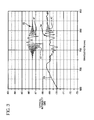
- a comparison of the simulation, curve 52 , with actual data, curve 54 is illustrated in FIG. 3 .
- the actual data were collected from a fiber having a peak bandwidth wavelength ⁇ p of approximately 770 nm and an operating wavelength ⁇ op of 850 nm.
- the decreasing intensity portion of the curve, 53 is indicative of the cut off wavelength for the third mode, that is, the wavelength above which the fiber supports two modes.
- the 2-mode fiber length was approximately 5 meters and had a measured bandwidth of 1.3 GHz-km at 850 nm.
- the simulated data has been offset from the actual data for clarity.
- the simulation was done using a wavelength data point spacing of 0.5 nm, a ⁇ p of 770 nm, and a full width half maximum (FWHM) spectral width of the source of 2 nm.
- FWHM full width half maximum
- the simulation is a very good match for the actual fiber data.
- both the actual data and the simulation clearly illustrate that in a fiber fabricated according to this aspect of the invention, the intensity modulation with wavelength caused by aliased detection of the optical interference between modes is directly related to intermodal noise 47 .
- This intermodal noise 47 is centered around the peak wavelength and decays dramatically at the operational wavelength, 850 nm.
- the decay of the spectral modulation or “coherence damping” is dependant on the linewidth of the light source. The more monochromatic the light, the more slowly the damping. Thus, a longer fiber length is required to ensure sufficient damping of intermodal noise at the end of the fiber.
- FIG. 4 simulated coherence damping curves for a 3 meter fiber length are compared. The damping curves 55 , 56 , and 57 were calculated using a wavelength data point spacing of 1.0 nm.
- FIGS. 5-12 illustrate simulated spectra for fibers of lengths varying from 10 meters to 5 kilometers. All of these spectra were generated with a peak wavelength of 770 nm, a data point spacing of 0.5 nm, and a FWHM source with a spectral width of 0.40 nm. The longer the fiber, the more quickly the intermodal noise attenuates as a function of wavelength. Thus, for long lengths of fiber, it is possible to design and operate a fiber with a peak wavelength closer to the actual operating wavelength. In the figures, ⁇ op is taken to be 850 nm. Curve 58 in FIG. 5, calculated for a 10 m fiber length shows modal noise level at the operation wavelength 59 to be about 0.5 dB.
- Combinations of fiber length and peak separation which the inventors have found to be particularly advantageous include, 10-20 m with the absolute value of the difference between ⁇ op and ⁇ p of approximately 80 to approximately 150 nm (bandwidth 0.6-1.2 GHz.km); 20-100 m with the absolute value of the difference between ⁇ op and ⁇ p of approximately 12 to approximately 80 nm (bandwidth 1.2-7 GHz.km); 100-1000 m with the absolute value of the difference between ⁇ op and ⁇ p of approximately 2 to approximately 12 nm (bandwidth 2-13 GHz.km); greater than 1000 m with the absolute value of the difference between ⁇ op and ⁇ p of approximately 0 to approximately 2 nm (bandwidth at least 3 GHz.km and preferably greater than 13 GHz.km).
Landscapes
- Physics & Mathematics (AREA)
- General Physics & Mathematics (AREA)
- Optics & Photonics (AREA)
- Chemical & Material Sciences (AREA)
- Dispersion Chemistry (AREA)
- Optical Communication System (AREA)
Priority Applications (6)
| Application Number | Priority Date | Filing Date | Title |
|---|---|---|---|
| US10/085,798 US6798962B2 (en) | 2002-02-26 | 2002-02-26 | Broadband access optimized fiber and method of making |
| AU2003213276A AU2003213276A1 (en) | 2002-02-26 | 2003-02-26 | Broadband access optimized fiber and method of making |
| EP03709327A EP1478956A4 (en) | 2002-02-26 | 2003-02-26 | FIBER OPTIMIZED FOR BROADBAND ACCESSION AND METHOD OF MANUFACTURING THEREOF |
| KR10-2004-7013350A KR20040078701A (ko) | 2002-02-26 | 2003-02-26 | 광대역 접근이 최적화된 광섬유 및 제조 방법 |
| PCT/US2003/005669 WO2003073140A1 (en) | 2002-02-26 | 2003-02-26 | Broadband access optimized fiber and method of making |
| JP2003571773A JP2005518564A (ja) | 2002-02-26 | 2003-02-26 | ブロードバンドアクセス用ファイバ及びその製造方法 |
Applications Claiming Priority (1)
| Application Number | Priority Date | Filing Date | Title |
|---|---|---|---|
| US10/085,798 US6798962B2 (en) | 2002-02-26 | 2002-02-26 | Broadband access optimized fiber and method of making |
Publications (2)
| Publication Number | Publication Date |
|---|---|
| US20030161597A1 US20030161597A1 (en) | 2003-08-28 |
| US6798962B2 true US6798962B2 (en) | 2004-09-28 |
Family
ID=27753719
Family Applications (1)
| Application Number | Title | Priority Date | Filing Date |
|---|---|---|---|
| US10/085,798 Expired - Lifetime US6798962B2 (en) | 2002-02-26 | 2002-02-26 | Broadband access optimized fiber and method of making |
Country Status (6)
| Country | Link |
|---|---|
| US (1) | US6798962B2 (enExample) |
| EP (1) | EP1478956A4 (enExample) |
| JP (1) | JP2005518564A (enExample) |
| KR (1) | KR20040078701A (enExample) |
| AU (1) | AU2003213276A1 (enExample) |
| WO (1) | WO2003073140A1 (enExample) |
Cited By (14)
| Publication number | Priority date | Publication date | Assignee | Title |
|---|---|---|---|---|
| US20050244120A1 (en) * | 2004-04-29 | 2005-11-03 | Mishra Snigdharaj K | Low attenuation large effective area optical fiber |
| US20060045450A1 (en) * | 2004-08-31 | 2006-03-02 | Bickham Scott R | Broadband optical fiber |
| US20060193561A1 (en) * | 2005-01-07 | 2006-08-31 | Jorg-Reinhard Kropp | Component and method for eccentric alignment of a first and a second pin, which each contain an optical fiber centrally, as well as a module assembly and a plug coupling having such a component |
| US20070196061A1 (en) * | 2006-02-21 | 2007-08-23 | Scott Robertson Bickham | Multiband optical fiber |
| US20100103978A1 (en) * | 2007-07-20 | 2010-04-29 | Chung Lee | Pure silica core multimode fiber sensoes for dts appications |
| US20130071114A1 (en) * | 2011-08-15 | 2013-03-21 | Scott Robertson Bickham | Few mode optical fibers for mode division multiplexing |
| US8565566B2 (en) | 2011-10-05 | 2013-10-22 | Sumitomo Electric Industries, Ltd. | Multi-mode optical fiber |
| US8565567B2 (en) | 2011-11-23 | 2013-10-22 | Sumitomo Electric Industries, Ltd. | Multi-mode optical fiber |
| WO2014021894A3 (en) * | 2012-08-02 | 2014-05-08 | Corning Incorporated | Few mode optical fibers for mode division multiplexing |
| US8891925B2 (en) | 2011-08-19 | 2014-11-18 | Corning Incorporated | Low bend loss optical fiber |
| US8995803B2 (en) | 2012-02-19 | 2015-03-31 | Corning Incorporated | Mode delay managed few moded optical fiber link |
| US9188736B2 (en) | 2013-04-08 | 2015-11-17 | Corning Incorporated | Low bend loss optical fiber |
| EP3143441A1 (en) * | 2014-05-16 | 2017-03-22 | Corning Incorporated | Multimode optical fiber and system including such |
| US10816734B2 (en) * | 2014-05-16 | 2020-10-27 | Corning Optical Communications LLC | Multimode optical transmission system employing modal-conditioning fiber |
Families Citing this family (8)
| Publication number | Priority date | Publication date | Assignee | Title |
|---|---|---|---|---|
| US6990277B2 (en) * | 2003-04-04 | 2006-01-24 | Fitel Usa Corp. | Enhanced multimode fiber |
| KR100672010B1 (ko) * | 2005-04-13 | 2007-01-22 | 한국과학기술원 | 광섬유와 이를 이용한 광가입자망, 구내 정보 통신망 및통신용 광부품 |
| US7876990B1 (en) * | 2009-11-25 | 2011-01-25 | Corning Incorporated | Low loss optical fiber |
| WO2013160714A1 (en) | 2012-04-27 | 2013-10-31 | Draka Comteq Bv | Hybrid single and multimode optical fiber for a home network |
| JP2015096938A (ja) * | 2013-10-11 | 2015-05-21 | 古河電気工業株式会社 | 光ファイバおよび光伝送システム |
| US10295734B2 (en) * | 2016-05-17 | 2019-05-21 | Corning Incorporated | Optical fiber for both multimode and single-mode operation and transmission system therefor |
| US12151964B2 (en) * | 2019-07-30 | 2024-11-26 | Corning Incorporated | Tension-based methods for forming bandwidth tuned optical fibers for bi-modal optical data transmission |
| WO2023192120A1 (en) * | 2022-04-01 | 2023-10-05 | Corning Incorporated | Methods of categorizing single mode optical fibers |
Citations (5)
| Publication number | Priority date | Publication date | Assignee | Title |
|---|---|---|---|---|
| US20020003938A1 (en) | 2000-05-31 | 2002-01-10 | V. Srikant | Dispersion managed fibers having reduced sensitivity to manufacturing variabilities |
| US20020006259A1 (en) | 1998-09-21 | 2002-01-17 | Tirloni Bartolomeo Italo | Optical fiber for extended wavelength band |
| US20020102082A1 (en) * | 1998-12-18 | 2002-08-01 | Davide Sarchi | Optical fiber for metropolitan and access network systems |
| US20030063875A1 (en) | 2001-07-06 | 2003-04-03 | Bickham Scott R. | Method of connecting optical fibers, an optical fiber therefor, and an optical fiber span therefrom |
| US6574403B1 (en) * | 2000-05-17 | 2003-06-03 | Fitel Usa Corp. | Apparatus and method for improving bandwidth of multimode optical fibers |
Family Cites Families (1)
| Publication number | Priority date | Publication date | Assignee | Title |
|---|---|---|---|---|
| US5684909A (en) * | 1996-02-23 | 1997-11-04 | Corning Inc | Large effective area single mode optical waveguide |
-
2002
- 2002-02-26 US US10/085,798 patent/US6798962B2/en not_active Expired - Lifetime
-
2003
- 2003-02-26 KR KR10-2004-7013350A patent/KR20040078701A/ko not_active Withdrawn
- 2003-02-26 JP JP2003571773A patent/JP2005518564A/ja active Pending
- 2003-02-26 WO PCT/US2003/005669 patent/WO2003073140A1/en not_active Ceased
- 2003-02-26 EP EP03709327A patent/EP1478956A4/en not_active Withdrawn
- 2003-02-26 AU AU2003213276A patent/AU2003213276A1/en not_active Abandoned
Patent Citations (5)
| Publication number | Priority date | Publication date | Assignee | Title |
|---|---|---|---|---|
| US20020006259A1 (en) | 1998-09-21 | 2002-01-17 | Tirloni Bartolomeo Italo | Optical fiber for extended wavelength band |
| US20020102082A1 (en) * | 1998-12-18 | 2002-08-01 | Davide Sarchi | Optical fiber for metropolitan and access network systems |
| US6574403B1 (en) * | 2000-05-17 | 2003-06-03 | Fitel Usa Corp. | Apparatus and method for improving bandwidth of multimode optical fibers |
| US20020003938A1 (en) | 2000-05-31 | 2002-01-10 | V. Srikant | Dispersion managed fibers having reduced sensitivity to manufacturing variabilities |
| US20030063875A1 (en) | 2001-07-06 | 2003-04-03 | Bickham Scott R. | Method of connecting optical fibers, an optical fiber therefor, and an optical fiber span therefrom |
Cited By (23)
| Publication number | Priority date | Publication date | Assignee | Title |
|---|---|---|---|---|
| US7187833B2 (en) | 2004-04-29 | 2007-03-06 | Corning Incorporated | Low attenuation large effective area optical fiber |
| US20070053642A1 (en) * | 2004-04-29 | 2007-03-08 | Mishra Snigdharaj K | Low attenuation large effective area optical fiber |
| US7254305B2 (en) | 2004-04-29 | 2007-08-07 | Corning Incorporated | Low attenuation large effective area optical fiber |
| US20050244120A1 (en) * | 2004-04-29 | 2005-11-03 | Mishra Snigdharaj K | Low attenuation large effective area optical fiber |
| US20060045450A1 (en) * | 2004-08-31 | 2006-03-02 | Bickham Scott R | Broadband optical fiber |
| US7336877B2 (en) | 2004-08-31 | 2008-02-26 | Corning Incorporated | Broadband optical fiber |
| US20060193561A1 (en) * | 2005-01-07 | 2006-08-31 | Jorg-Reinhard Kropp | Component and method for eccentric alignment of a first and a second pin, which each contain an optical fiber centrally, as well as a module assembly and a plug coupling having such a component |
| US20070196061A1 (en) * | 2006-02-21 | 2007-08-23 | Scott Robertson Bickham | Multiband optical fiber |
| US7406237B2 (en) | 2006-02-21 | 2008-07-29 | Corning Incorporated | Multiband optical fiber |
| US8414186B2 (en) | 2007-07-20 | 2013-04-09 | Sensortran, Inc. | Pure silica core multimode fiber sensors for DTS applications |
| US20100103978A1 (en) * | 2007-07-20 | 2010-04-29 | Chung Lee | Pure silica core multimode fiber sensoes for dts appications |
| US20130071114A1 (en) * | 2011-08-15 | 2013-03-21 | Scott Robertson Bickham | Few mode optical fibers for mode division multiplexing |
| US8693834B2 (en) * | 2011-08-15 | 2014-04-08 | Corning Incorporated | Few mode optical fibers for mode division multiplexing |
| US8891925B2 (en) | 2011-08-19 | 2014-11-18 | Corning Incorporated | Low bend loss optical fiber |
| US8565566B2 (en) | 2011-10-05 | 2013-10-22 | Sumitomo Electric Industries, Ltd. | Multi-mode optical fiber |
| US8565567B2 (en) | 2011-11-23 | 2013-10-22 | Sumitomo Electric Industries, Ltd. | Multi-mode optical fiber |
| US8995803B2 (en) | 2012-02-19 | 2015-03-31 | Corning Incorporated | Mode delay managed few moded optical fiber link |
| WO2014021894A3 (en) * | 2012-08-02 | 2014-05-08 | Corning Incorporated | Few mode optical fibers for mode division multiplexing |
| CN104067152A (zh) * | 2012-08-02 | 2014-09-24 | 康宁股份有限公司 | 用于模分多路复用的少模光纤 |
| CN104067152B (zh) * | 2012-08-02 | 2017-05-10 | 康宁股份有限公司 | 用于模分多路复用的少模光纤 |
| US9188736B2 (en) | 2013-04-08 | 2015-11-17 | Corning Incorporated | Low bend loss optical fiber |
| EP3143441A1 (en) * | 2014-05-16 | 2017-03-22 | Corning Incorporated | Multimode optical fiber and system including such |
| US10816734B2 (en) * | 2014-05-16 | 2020-10-27 | Corning Optical Communications LLC | Multimode optical transmission system employing modal-conditioning fiber |
Also Published As
| Publication number | Publication date |
|---|---|
| KR20040078701A (ko) | 2004-09-10 |
| JP2005518564A (ja) | 2005-06-23 |
| EP1478956A4 (en) | 2006-12-13 |
| EP1478956A1 (en) | 2004-11-24 |
| US20030161597A1 (en) | 2003-08-28 |
| AU2003213276A1 (en) | 2003-09-09 |
| WO2003073140A1 (en) | 2003-09-04 |
Similar Documents
| Publication | Publication Date | Title |
|---|---|---|
| US6798962B2 (en) | Broadband access optimized fiber and method of making | |
| Anderson et al. | Troubleshooting optical fiber networks: understanding and using optical time-domain reflectometers | |
| Tateda et al. | First measurement of strain distribution along field-installed optical fibers using Brillouin spectroscopy | |
| US7526169B2 (en) | Low bend loss quasi-single-mode optical fiber and optical fiber line | |
| US8547541B2 (en) | Method for the characterization of optical properties of an optical fiber | |
| US8531654B2 (en) | Method for designing and selecting optical fiber for use with a transmitter optical subassembly | |
| US20170331549A1 (en) | Method for characterizing performance of a multimode fiber optical link and corresponding methods for fabricating a multimode optical fiber link showing improved performance and for improving performance of a multimode optical fiber link | |
| US7221439B2 (en) | Method of estimating and measuring longitudinal dispersion in optical fibers | |
| US6665481B2 (en) | Low MPI dispersion compensating fiber | |
| Unger et al. | Investigation of the microbending sensitivity of fibers | |
| US20020154877A1 (en) | Waveguide fiber for dispersion and slope compensation | |
| Chen et al. | Testing MPI threshold in bend insensitive fiber using coherent peak-to-peak power method | |
| JP2025506457A (ja) | 中空コア光ファイバのための光時間領域反射測定 | |
| Geisler et al. | Large area, ultra low loss, trench assisted fiber with l band edf enabling future c+ l band submarine cable systems | |
| Sunak | Single-mode fiber measurements | |
| JP3137585B2 (ja) | マイクロベンディング量の測定方法 | |
| Day et al. | Optical fiber metrology | |
| Hartog et al. | Comparison of measured and predicted bandwidth of graded-index multimode fibers | |
| Kapron | Issues in single-mode fiber standardization | |
| Girard | Measuring Fiber Characteristics | |
| Widodo et al. | Attenuation and received power estimation in single-mode fiber optic installation using OTDR and OPM | |
| Coppa et al. | Characterization of single-mode optical fibres | |
| Love | Waveguide fiber standards | |
| Qian et al. | Impact study of multimode fibre taper in modal noise under restricted offset launch conditions | |
| Coppa et al. | Single-mode optical fiber characterization |
Legal Events
| Date | Code | Title | Description |
|---|---|---|---|
| AS | Assignment |
Owner name: CORNING INCORPORATED, NEW YORK Free format text: ASSIGNMENT OF ASSIGNORS INTEREST;ASSIGNORS:BERKEY, GEORGE E.;LOVE, WALTER F.;MA, DAIPING;REEL/FRAME:013855/0663;SIGNING DATES FROM 20030610 TO 20030625 |
|
| STCF | Information on status: patent grant |
Free format text: PATENTED CASE |
|
| CC | Certificate of correction | ||
| FPAY | Fee payment |
Year of fee payment: 4 |
|
| REMI | Maintenance fee reminder mailed | ||
| FPAY | Fee payment |
Year of fee payment: 8 |
|
| FPAY | Fee payment |
Year of fee payment: 12 |