US6795284B2 - Device for stopping a single-phase asynchronous motor with phase-shifting capacitor - Google Patents
Device for stopping a single-phase asynchronous motor with phase-shifting capacitor Download PDFInfo
- Publication number
- US6795284B2 US6795284B2 US10/239,016 US23901602A US6795284B2 US 6795284 B2 US6795284 B2 US 6795284B2 US 23901602 A US23901602 A US 23901602A US 6795284 B2 US6795284 B2 US 6795284B2
- Authority
- US
- United States
- Prior art keywords
- voltage
- stopping device
- transformed
- motor
- torque
- Prior art date
- Legal status (The legal status is an assumption and is not a legal conclusion. Google has not performed a legal analysis and makes no representation as to the accuracy of the status listed.)
- Expired - Fee Related, expires
Links
Images


Classifications
-
- H—ELECTRICITY
- H02—GENERATION; CONVERSION OR DISTRIBUTION OF ELECTRIC POWER
- H02H—EMERGENCY PROTECTIVE CIRCUIT ARRANGEMENTS
- H02H3/00—Emergency protective circuit arrangements for automatic disconnection directly responsive to an undesired change from normal electric working condition with or without subsequent reconnection ; integrated protection
- H02H3/38—Emergency protective circuit arrangements for automatic disconnection directly responsive to an undesired change from normal electric working condition with or without subsequent reconnection ; integrated protection responsive to both voltage and current; responsive to phase angle between voltage and current
-
- H—ELECTRICITY
- H02—GENERATION; CONVERSION OR DISTRIBUTION OF ELECTRIC POWER
- H02H—EMERGENCY PROTECTIVE CIRCUIT ARRANGEMENTS
- H02H7/00—Emergency protective circuit arrangements specially adapted for specific types of electric machines or apparatus or for sectionalised protection of cable or line systems, and effecting automatic switching in the event of an undesired change from normal working conditions
- H02H7/08—Emergency protective circuit arrangements specially adapted for specific types of electric machines or apparatus or for sectionalised protection of cable or line systems, and effecting automatic switching in the event of an undesired change from normal working conditions for dynamo-electric motors
- H02H7/085—Emergency protective circuit arrangements specially adapted for specific types of electric machines or apparatus or for sectionalised protection of cable or line systems, and effecting automatic switching in the event of an undesired change from normal working conditions for dynamo-electric motors against excessive load
Definitions
- the subject of the invention is a stopping device for a single-phase asynchronous motor with phase shifting capacitor using the variation in the voltage across the terminals of the phase shifting capacitor as a function of the motor speed itself varying with load, so as to stop the motor when the load on the motor exceeds a specified value.
- Such a device is described in patent FR 2 649 260.
- This device comprises a circuit delivering a DC voltage homothetic to the voltage across the terminals of the phase shifting capacitor of the motor, a circuit delivering at least one constant reference voltage and a comparator circuit comparing these two voltages and delivering a stop signal when the homothetic DC voltage becomes equal to or less than the reference voltage.
- Such a circuit is especially useful as safety device for stopping the motor of an installation in which the load driven by the motor is at risk of encountering an obstacle with the attendant risks of damage or impairment of the installation.
- Motorized shutters, blinds and doors may be mentioned by way of example.
- a similar device is described in patent EP 0 551 053.
- This device furthermore comprises means of compensation for taking account of the fluctuation of the voltage across the terminals of the phase shifting capacitor with the temperature of the motor.
- the reference voltage consists preferably of a voltage slaved to the voltage of the power supply so as to circumvent fluctuations of this voltage.
- the measured voltage is applied to a transformer followed by a rectifier circuit before being applied to one of the inputs of a comparator circuit, the transformation ratio being substantially equal to 30.
- the variation in voltage across the terminals of the capacitor will be 100V/4, that is to say 25V, while for a motor developing a maximum torque of 40N the variation in voltage across the terminals of the capacitor will be 100V/40, that is to say 2.5V.
- the aim of the invention is to remedy this drawback.
- the stopping device is characterized in that it comprises means for transforming the variation in the voltage across the terminals of the phase shifting capacitor corresponding to a torque variation of 1N into a chosen variation of the voltage regardless of the maximum power of the motor, means for comparing this chosen variation with a reference voltage and means for stopping the motor when the transformed voltage is less than the reference voltage.
- the means for transforming the voltage comprise a voltage rectifier, a voltage reducer and a voltage divider to which is applied the voltage obtained after the voltage reducer.
- the voltage reducer preferably consists of a Zener diode, which constitutes the ideal means of achieving a voltage drop.
- the voltage drop could however be obtained by means of an ad hoc circuit.
- the divided voltage can be processed by means of an analog circuit or, by sampling, by means of a microprocessor.
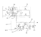
- FIG. 1 is the electrical diagram of a mode of execution with analog arrangement.
- FIG. 2 represents the shape of the voltages at the points A, B and E of the circuit according to FIG. 1 .
- FIG. 3 represents a mode of execution with microprocessor therefore using analog/digital conversion.
- FIG. 4 illustrates the mode of measurement by sampling of the mode of execution represented in FIG. 3 .
- FIG. 5 partially represents a variant of the above modes of execution.
- the single-phase motor M is represented as is customary by its two windings B 1 and B 2 and by its phase shifting capacitor C.
- This motor is supplied from a single-phase current source P across one or other of the switches I 1 or I 2 .
- the switch I 1 is closed the winding B 1 constitutes the main winding and B 2 the auxiliary winding and the motor turns in one direction
- the switch 12 is closed it is the winding B 2 which plays the role of main winding and the winding B 1 the role of auxiliary winding and the motor turns in the other direction.
- phase shifting capacitor C Between the terminals of the phase shifting capacitor C are wired up in series a diode D 1 , a Zener diode DZ, a resistor R 1 and a resistor R 2 in parallel with which a chemical capacitor C 1 is wired.
- the diode D 1 constitutes a voltage rectifier Rd, the Zener diode a voltage reducer Ch and the resistors R 1 and R 2 a voltage divider Div. As far as R 2 and C 1 are concerned, they together constitute a first integrator circuit Int exhibiting a time constant ⁇ 1. These components are surrounded by a broken thin line in FIG. 1 .
- the midpoint B of the voltage divider is linked, on the one hand, to the base of a transistor T 1 and, on the other hand, to the anode of a diode D 2 whose cathode is linked to the emitter of T 1 , this emitter furthermore being linked to ground through a resistor R 3 in parallel with a chemical capacitor C 2 constituting a second integrator circuit Int with time constant ⁇ 2.
- These components constitute, with the integrator R 2 -C 1 , a processing unit UT.
- the transistor T 1 constitutes a floating comparator.
- the collector of the transistor T 1 is linked to the gate of a MOS transistor T 2 biased by a resistor R 5 .
- the source of T 2 is linked to ground while its drain is linked to the base of T 1 across a resistor R 4 . It is on this drain, at F, that one obtains the signal controlling the stoppage of the motor when the detected resisting torque exceeds a specified threshold.
- the diode D 1 eliminates the negative half-waves of the voltage across the terminals of C in such a way as to be able to work ultimately with a quasi-DC current at the level of the processing unit.
- the essential components of the circuit are the voltage reducer and the divider. To illustrate their role we shall examine two motors of substantially different power.
- the motor develops a maximum torque of 50N.
- the torque varies from 0 to 50N
- the voltage drop across the terminals of C is the same as before.
- For a variation in the torque of 1N there is therefore in this case a voltage variation of 2V across the terminals of C.
- the diode DZ must therefore exhibit a Zener voltage equal to 510V.
- the voltage at the midpoint of the divider is integrated by the first integrator R 2 -C 1 .
- the voltage at the point B is the voltage which is the image of the torque. It has the shape represented at B in FIG. 2 .
- This voltage is, on the one hand, applied to the base of the transistor T 1 , and, on the other hand, it is used to create a reference voltage at the point E, that is to say on the emitter of T 1 .
- it is applied across the diode D 1 to the integrator C 2 -R 3 whose time constant, that is to say the discharge constant ⁇ 2 is x times greater than ⁇ 1, x being much larger than 1.
- the diode D 2 separates the integrator C 2 -R 3 from the integrator C 1 -R 2 by preventing the capacitor C 2 from discharging across R 2 .
- U B U E +U D
- the reference voltage remains practically constant as long as there is a voltage at B.
- T 1 As long as the torque image voltage applied to the base of T 1 has not fallen below the reference value, that is to say the critical or threshold value, T 1 is off and the voltage at the point G 1 of its collector is equal to 0V. If the torque image voltage falls below the critical threshold, T 1 comes on and the current across R 5 creates a voltage at G greater than 0V. T 2 comes on and a stop signal appears at the point F.
- the signal at the output F can be processed in any known manner.
- the voltage obtained at the midpoint of the divider R 1 /R 2 can be processed digitally by means of a microprocessor ⁇ P, as represented diagrammatically in FIG. 3 .
- the microprocessor must be equipped with an analog/digital converter. Sampling is preferably employed, as illustrated by FIG. 4 .
- the peak value of the voltage U B is detected every 20 ms for example. As long as the peaks in the half-waves are decreasing (this signifying that the resisting torque is increasing), or are equal, the difference of the peak values between half-waves nt4 and n is measured. If this value, that is to say the slope of the straight line x, exceeds a given threshold, the motor is stopped.
- FIG. 5 illustrates one way of achieving this variant execution. Only the resistors R 1 and R 2 of the voltage divider from the circuits represented in FIGS. 1 and 3 have been represented here.
- the modification consists in adding a transistor T 3 , here in parallel with R 2 , and a resistor R 6 wired up between the collector of the transistor T 3 and the midpoint of the voltage divider R 1 /R 2 .
- the transistor T 3 operates as a switch controlled by a voltage applied to its base. T 3 is controlled by a timer during the energizing of the device.
- the transistor T 3 is on and the resistor R 6 is then in parallel with R 2 .
- a first reference voltage level is recorded by the capacitor C 2 .
- T 3 is turned off by the timer, this having the effect of disconnecting R 6 .
- the reference voltage takes a new value which approximates the voltage corresponding to the normal torque of the motor during operation.
- the transistor T 3 could be operated directly by the microprocessor.
Landscapes
- Control Of Ac Motors In General (AREA)
- Stopping Of Electric Motors (AREA)
- Window Of Vehicle (AREA)
- Protection Of Generators And Motors (AREA)
- Control Of Motors That Do Not Use Commutators (AREA)
- Control Of Vehicle Engines Or Engines For Specific Uses (AREA)
- Combined Controls Of Internal Combustion Engines (AREA)
- Force Measurement Appropriate To Specific Purposes (AREA)
- Oscillators With Electromechanical Resonators (AREA)
Applications Claiming Priority (3)
| Application Number | Priority Date | Filing Date | Title |
|---|---|---|---|
| FR0003853 | 2000-03-27 | ||
| FR0003853A FR2806850B1 (fr) | 2000-03-27 | 2000-03-27 | Dispositif d'arret d'un moteur asynchrone monophase a condensateur de dephasage |
| PCT/IB2001/000494 WO2001073913A1 (fr) | 2000-03-27 | 2001-03-23 | Dispositif d'arret d'un moteur asynchrone monophase a condensateur de dephasage |
Publications (2)
| Publication Number | Publication Date |
|---|---|
| US20030030950A1 US20030030950A1 (en) | 2003-02-13 |
| US6795284B2 true US6795284B2 (en) | 2004-09-21 |
Family
ID=8848529
Family Applications (1)
| Application Number | Title | Priority Date | Filing Date |
|---|---|---|---|
| US10/239,016 Expired - Fee Related US6795284B2 (en) | 2000-03-27 | 2001-03-23 | Device for stopping a single-phase asynchronous motor with phase-shifting capacitor |
Country Status (10)
| Country | Link |
|---|---|
| US (1) | US6795284B2 (de) |
| EP (1) | EP1269596B1 (de) |
| JP (1) | JP5026652B2 (de) |
| CN (1) | CN100486070C (de) |
| AT (1) | ATE483268T1 (de) |
| AU (1) | AU2001240994A1 (de) |
| DE (1) | DE60143159D1 (de) |
| ES (1) | ES2185521T1 (de) |
| FR (1) | FR2806850B1 (de) |
| WO (1) | WO2001073913A1 (de) |
Cited By (4)
| Publication number | Priority date | Publication date | Assignee | Title |
|---|---|---|---|---|
| US20050097821A1 (en) * | 2001-10-17 | 2005-05-12 | Norbert Knab | Method for monitoring the reversing process of electrically actuatable units |
| US20060185799A1 (en) * | 2005-02-24 | 2006-08-24 | Lawrence Kates | Motorized window shade system |
| US20090308543A1 (en) * | 2008-06-13 | 2009-12-17 | Lawrence Kates | Motorized window shade system and mount |
| EP3249089A1 (de) | 2016-05-23 | 2017-11-29 | Electrolux Appliances Aktiebolag | Wäschebehandlungsvorrichtung |
Families Citing this family (11)
| Publication number | Priority date | Publication date | Assignee | Title |
|---|---|---|---|---|
| EP1389817A1 (de) * | 2002-07-26 | 2004-02-18 | STMicroelectronics S.r.l. | Verfahren und Schaltung zur Erfassung von Drehmomentschwankungen eines elektrischen Gleichstrommotors |
| FR2849300B1 (fr) * | 2002-12-20 | 2005-02-11 | Somfy | Dispositif de commande de l'alimentation d'un moteur asynchrone et de mesure du couple moteur. |
| DE102004029118A1 (de) * | 2004-06-17 | 2006-01-12 | Bontronic Steuerungstechnik Gmbh | Verfahren zur Messung des Lastzustandes eines Einphasen-Wechselstrommotors |
| CN100479289C (zh) * | 2004-09-15 | 2009-04-15 | 台达电子工业股份有限公司 | 马达驱动保护电路 |
| FR2879856B1 (fr) * | 2004-12-21 | 2008-07-04 | Somfy Sas | Procede de fonctionnement d'une installation domotique comprenant un actionneur et une unite de commande |
| US7737653B2 (en) * | 2007-04-17 | 2010-06-15 | Lutron Electronics Co., Inc. | Method of controlling a motorized window treatment |
| US7839109B2 (en) * | 2007-04-17 | 2010-11-23 | Lutron Electronics Co., Inc. | Method of controlling a motorized window treatment |
| FR2923508B1 (fr) | 2007-11-13 | 2009-12-25 | Somfy Sas | Procede de fonctionnement d'un actionneur electromecanique pour store a bras |
| FR2925932B1 (fr) | 2007-12-26 | 2011-08-26 | Somfy Sas | Procede de reglage d'une installation de protection solaire motorisee ne comprenant pas de butee franche. |
| FR2928502B1 (fr) * | 2008-03-05 | 2011-09-23 | Somfy Sas | Procede de transformation des tensions aux bornes des enroulements d'un moteur electrique monophase a induction et condensateur permanent |
| JP5192027B2 (ja) * | 2010-11-13 | 2013-05-08 | ソムフィ株式会社 | 電動シャッター制御方法 |
Citations (8)
| Publication number | Priority date | Publication date | Assignee | Title |
|---|---|---|---|---|
| US4722019A (en) | 1985-09-20 | 1988-01-26 | General Electric Company | Protection methods and systems for refrigeration systems suitable for a variety of different models |
| FR2649260A1 (fr) | 1989-06-30 | 1991-01-04 | Somfy | Dispositif d'arret d'un moteur asynchrone monophase a condensateur |
| DE4211495A1 (de) | 1992-04-06 | 1993-03-18 | Goller Albert | Vorrichtung zur drehmomentabschaltung eines kondensatormotors |
| EP0551053A1 (de) | 1991-12-30 | 1993-07-14 | Somfy | Vorrichtung zum Anhalten einer einphasigen Asynchronmaschine mit Kondensator |
| US5705903A (en) * | 1996-02-12 | 1998-01-06 | Unicoil, Inc. | Electric brake for an alternating current motor |
| US5760566A (en) * | 1994-12-29 | 1998-06-02 | Plumer, Societe Anonyme | Control device for stopping the operation of a single-phase asynchronous motor with a capacitor |
| US5850131A (en) * | 1995-10-28 | 1998-12-15 | Elero Gmbh | Process for driving electric motor-operated awnings |
| US6104156A (en) * | 1998-06-16 | 2000-08-15 | Somfy | Device for controlling the stopping of a motorized shrouding product |
Family Cites Families (2)
| Publication number | Priority date | Publication date | Assignee | Title |
|---|---|---|---|---|
| JPH04320744A (ja) * | 1991-04-18 | 1992-11-11 | Toshiba Corp | 換気装置の異常検出装置 |
| JPH09163699A (ja) * | 1995-12-11 | 1997-06-20 | Yuasa Tsushinki Kogyo Kk | コンデンサモータの過負荷検知方法 |
-
2000
- 2000-03-27 FR FR0003853A patent/FR2806850B1/fr not_active Expired - Fee Related
-
2001
- 2001-03-23 AT AT01912078T patent/ATE483268T1/de not_active IP Right Cessation
- 2001-03-23 AU AU2001240994A patent/AU2001240994A1/en not_active Abandoned
- 2001-03-23 DE DE60143159T patent/DE60143159D1/de not_active Expired - Lifetime
- 2001-03-23 ES ES01912078T patent/ES2185521T1/es active Pending
- 2001-03-23 WO PCT/IB2001/000494 patent/WO2001073913A1/fr not_active Ceased
- 2001-03-23 EP EP01912078A patent/EP1269596B1/de not_active Expired - Lifetime
- 2001-03-23 CN CNB018073204A patent/CN100486070C/zh not_active Expired - Fee Related
- 2001-03-23 JP JP2001571526A patent/JP5026652B2/ja not_active Expired - Fee Related
- 2001-03-23 US US10/239,016 patent/US6795284B2/en not_active Expired - Fee Related
Patent Citations (9)
| Publication number | Priority date | Publication date | Assignee | Title |
|---|---|---|---|---|
| US4722019A (en) | 1985-09-20 | 1988-01-26 | General Electric Company | Protection methods and systems for refrigeration systems suitable for a variety of different models |
| FR2649260A1 (fr) | 1989-06-30 | 1991-01-04 | Somfy | Dispositif d'arret d'un moteur asynchrone monophase a condensateur |
| EP0408493A1 (de) | 1989-06-30 | 1991-01-16 | Somfy | Abschaltvorrichtung für einen einphasigen Asynchronmotor mit Kondensator |
| EP0551053A1 (de) | 1991-12-30 | 1993-07-14 | Somfy | Vorrichtung zum Anhalten einer einphasigen Asynchronmaschine mit Kondensator |
| DE4211495A1 (de) | 1992-04-06 | 1993-03-18 | Goller Albert | Vorrichtung zur drehmomentabschaltung eines kondensatormotors |
| US5760566A (en) * | 1994-12-29 | 1998-06-02 | Plumer, Societe Anonyme | Control device for stopping the operation of a single-phase asynchronous motor with a capacitor |
| US5850131A (en) * | 1995-10-28 | 1998-12-15 | Elero Gmbh | Process for driving electric motor-operated awnings |
| US5705903A (en) * | 1996-02-12 | 1998-01-06 | Unicoil, Inc. | Electric brake for an alternating current motor |
| US6104156A (en) * | 1998-06-16 | 2000-08-15 | Somfy | Device for controlling the stopping of a motorized shrouding product |
Non-Patent Citations (1)
| Title |
|---|
| International Search Report in SN PCT/IB 01/00494. |
Cited By (6)
| Publication number | Priority date | Publication date | Assignee | Title |
|---|---|---|---|---|
| US20050097821A1 (en) * | 2001-10-17 | 2005-05-12 | Norbert Knab | Method for monitoring the reversing process of electrically actuatable units |
| US7122981B2 (en) * | 2001-10-17 | 2006-10-17 | Robert Bosch Gmbh | Method for monitoring the reversing process of electrically actuatable units |
| US20060185799A1 (en) * | 2005-02-24 | 2006-08-24 | Lawrence Kates | Motorized window shade system |
| US7389806B2 (en) | 2005-02-24 | 2008-06-24 | Lawrence Kates | Motorized window shade system |
| US20090308543A1 (en) * | 2008-06-13 | 2009-12-17 | Lawrence Kates | Motorized window shade system and mount |
| EP3249089A1 (de) | 2016-05-23 | 2017-11-29 | Electrolux Appliances Aktiebolag | Wäschebehandlungsvorrichtung |
Also Published As
| Publication number | Publication date |
|---|---|
| ATE483268T1 (de) | 2010-10-15 |
| EP1269596A1 (de) | 2003-01-02 |
| JP5026652B2 (ja) | 2012-09-12 |
| DE60143159D1 (de) | 2010-11-11 |
| WO2001073913A1 (fr) | 2001-10-04 |
| EP1269596B1 (de) | 2010-09-29 |
| AU2001240994A1 (en) | 2001-10-08 |
| US20030030950A1 (en) | 2003-02-13 |
| ES2185521T1 (es) | 2003-05-01 |
| FR2806850A1 (fr) | 2001-09-28 |
| JP2003529307A (ja) | 2003-09-30 |
| CN100486070C (zh) | 2009-05-06 |
| CN1419726A (zh) | 2003-05-21 |
| FR2806850B1 (fr) | 2002-05-24 |
Similar Documents
| Publication | Publication Date | Title |
|---|---|---|
| US6795284B2 (en) | Device for stopping a single-phase asynchronous motor with phase-shifting capacitor | |
| US8232755B2 (en) | Motor with circuits for protecting motor from input power outages or surges | |
| US7570498B2 (en) | Switching power supply apparatus for correcting overcurrent detection point based on gradient of switching current | |
| US7812586B2 (en) | One cycle control PFC circuit with dynamic gain modulation | |
| IE53890B1 (en) | Motor power factor controller with a reduced voltage starter | |
| EP1146620B1 (de) | Verfahren zur Steuerung eines Halbleiter-Schaltelementes und nach diesem Verfahren gesteuertes Schaltnetzteilgerät | |
| JPH06311734A (ja) | 出力短絡保護回路 | |
| US20150280625A1 (en) | Apparatus for detecting the rotor position of an electric motor and related method | |
| US10840696B2 (en) | Method and apparatus for limiting the output voltages of switch mode power supplies | |
| KR100504857B1 (ko) | 멀티 에어컨의 인버터 구동장치 | |
| JP2728568B2 (ja) | 直流安定化電源装置 | |
| US20060152270A1 (en) | Circuit arrangement for electrically isolated signal transmission | |
| KR101300379B1 (ko) | 보호 기능을 갖는 전원 공급 장치 | |
| JP2007129875A (ja) | 突入電流防止回路 | |
| CN106415985B (zh) | 取决于输出电流在工作和待机间转换的供能设备 | |
| JPH0537665Y2 (de) | ||
| JPH07101093B2 (ja) | 燃焼器の電源異状検出装置 | |
| JPH0270265A (ja) | スイッチング電源装置 | |
| KR910006691Y1 (ko) | 스탠바이 전원을 이용한 서브 전원 공급회로 | |
| JPH0779545B2 (ja) | スイツチング電源 | |
| KR19980016283U (ko) | 스위치드 릴럭턴스 모터의 과전류 방지 회로 | |
| KR19990041763A (ko) | 냉장고용 스위칭모드 전원공급기 제어회로 및 그 제어방법 | |
| JP2000134929A (ja) | 電流共振回路および電流共振回路を用いた電源装置 | |
| JPS63128270A (ja) | 電解コンデンサの劣化検出回路 | |
| JPH08322281A (ja) | 直流ブラシレスモータの保護装置 |
Legal Events
| Date | Code | Title | Description |
|---|---|---|---|
| AS | Assignment |
Owner name: SOMFY, FRANCE Free format text: ASSIGNMENT OF ASSIGNORS INTEREST;ASSIGNOR:BRUNO, SERGE;REEL/FRAME:013489/0658 Effective date: 20020801 |
|
| AS | Assignment |
Owner name: SOMFY, FRANCE Free format text: ASSIGNMENT OF ASSIGNORS INTEREST;ASSIGNOR:SOMFY;REEL/FRAME:015522/0312 Effective date: 20040303 |
|
| FPAY | Fee payment |
Year of fee payment: 4 |
|
| FPAY | Fee payment |
Year of fee payment: 8 |
|
| REMI | Maintenance fee reminder mailed | ||
| LAPS | Lapse for failure to pay maintenance fees | ||
| STCH | Information on status: patent discontinuation |
Free format text: PATENT EXPIRED DUE TO NONPAYMENT OF MAINTENANCE FEES UNDER 37 CFR 1.362 |
|
| STCH | Information on status: patent discontinuation |
Free format text: PATENT EXPIRED DUE TO NONPAYMENT OF MAINTENANCE FEES UNDER 37 CFR 1.362 |
|
| FP | Lapsed due to failure to pay maintenance fee |
Effective date: 20160921 |