US6787263B2 - Method and apparatus for establishing a negative pressure inside an enclosure that houses a fuel cell system - Google Patents
Method and apparatus for establishing a negative pressure inside an enclosure that houses a fuel cell system Download PDFInfo
- Publication number
- US6787263B2 US6787263B2 US10/421,568 US42156803A US6787263B2 US 6787263 B2 US6787263 B2 US 6787263B2 US 42156803 A US42156803 A US 42156803A US 6787263 B2 US6787263 B2 US 6787263B2
- Authority
- US
- United States
- Prior art keywords
- fuel cell
- enclosure
- cell system
- air
- damper
- Prior art date
- Legal status (The legal status is an assumption and is not a legal conclusion. Google has not performed a legal analysis and makes no representation as to the accuracy of the status listed.)
- Expired - Lifetime
Links
Images


Classifications
-
- H—ELECTRICITY
- H01—ELECTRIC ELEMENTS
- H01M—PROCESSES OR MEANS, e.g. BATTERIES, FOR THE DIRECT CONVERSION OF CHEMICAL ENERGY INTO ELECTRICAL ENERGY
- H01M8/00—Fuel cells; Manufacture thereof
- H01M8/04—Auxiliary arrangements, e.g. for control of pressure or for circulation of fluids
- H01M8/04082—Arrangements for control of reactant parameters, e.g. pressure or concentration
- H01M8/04089—Arrangements for control of reactant parameters, e.g. pressure or concentration of gaseous reactants
- H01M8/04104—Regulation of differential pressures
-
- Y—GENERAL TAGGING OF NEW TECHNOLOGICAL DEVELOPMENTS; GENERAL TAGGING OF CROSS-SECTIONAL TECHNOLOGIES SPANNING OVER SEVERAL SECTIONS OF THE IPC; TECHNICAL SUBJECTS COVERED BY FORMER USPC CROSS-REFERENCE ART COLLECTIONS [XRACs] AND DIGESTS
- Y02—TECHNOLOGIES OR APPLICATIONS FOR MITIGATION OR ADAPTATION AGAINST CLIMATE CHANGE
- Y02E—REDUCTION OF GREENHOUSE GAS [GHG] EMISSIONS, RELATED TO ENERGY GENERATION, TRANSMISSION OR DISTRIBUTION
- Y02E60/00—Enabling technologies; Technologies with a potential or indirect contribution to GHG emissions mitigation
- Y02E60/30—Hydrogen technology
- Y02E60/50—Fuel cells
Definitions
- the invention relates to a method and apparatus for establishing a negative pressure inside an enclosure that houses a fuel cell system.
- a fuel cell is an electrochemical device that converts chemical energy that is produced by a reaction directly into electrical energy.
- one type of fuel cell includes a proton exchange membrane (PEM), often called a polymer electrolyte membrane, that permits only protons to pass between an anode and a cathode of the fuel cell.
- PEM proton exchange membrane
- diatomic hydrogen a fuel
- the electrons produced by this reaction travel through circuitry that is external to the fuel cell to form an electrical current.
- oxygen is reduced and reacts with the hydrogen protons to form water.
- the fuel cell stack may include plates (graphite composite or metal plates, as examples) that are stacked one on top of the other, and each plate may be associated with more than one fuel cell of the stack.
- the plates may include various channels and orifices to, as examples, route the reactants and products through the fuel cell stack.
- PEMs Several PEMs (each one being associated with a particular fuel cell) may be dispersed throughout the stack between the anodes and cathodes of the different fuel cells.
- the fuel cell stack typically is housed in an enclosure that encloses the stack and other components of a fuel cell system.
- the fuel cell system may leak small amounts of gases, such as hydrogen, for example.
- gases such as hydrogen, for example.
- a blower may be located inside the enclosure to establish a positive pressure inside the enclosure to both dilute any stray gases and force the diluted gases outside of the enclosure. Because the stray gases must be diluted to a very small concentration outside of the enclosure, typically the blower must generate a large air flow, an air flow that might freeze compartments of the fuel cell system.
- a fuel cell system in an embodiment of the invention, includes a fuel cell stack, an enclosure housing the fuel cell stack and a blower that is located inside the enclosure.
- the blower is adapted to draw air from an interior of the enclosure to produce an air flow through the fuel cell stack and establish a negative pressure inside the enclosure with respect to a region outside of the enclosure.
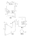
- FIG. 1 is a perspective view of a fuel cell system according to an embodiment of the invention.
- FIG. 2 is a front view of the fuel cell system of FIG. 1 according to an embodiment of the invention.
- FIG. 3 is a rear view of the fuel cell system of FIG. 1 according to an embodiment of the invention.
- FIG. 4 is a side view of an air flow hood of the system according to an embodiment of the invention.
- FIG. 4A is a top view of a damper flap according to an embodiment of the invention.
- FIG. 5 illustrates pressure versus air flow curves to illustrate operation of a damper according to an embodiment of the invention.
- FIG. 6 is a top view of a louver of the fuel cell system according to an embodiment of the invention.
- FIG. 7 is a cross-sectional view of the louver taken along line 7 — 7 of FIG. 6 .
- FIG. 8 depicts a cross-sectional view of the louver taken along line 8 — 8 of FIG. 6 .
- FIG. 8A depicts a side view of the louver according to an embodiment of the invention.
- FIG. 9 is a more detailed schematic diagram of the components of the fuel cell system according to an embodiment of the invention.
- an embodiment 7 of a fuel cell system in accordance with the invention includes an enclosure, or cabinet 11 .
- the cabinet 11 houses components of the fuel cell system 7 , such as a blower 20 .
- the blower 20 draws air from an interior region 18 of the cabinet 11 to establish an air flow that supplies oxygen (a reactant) to a fuel cell stack of the system 7 .
- the blower 20 and other components 19 are contained within the interior region 18 of the cabinet 11 .
- the components 19 may leak a small amount of gas (hydrogen, as an example).
- the negative cabinet pressure that is established by the above-described arrangement is to be contrasted with conventional arrangements that may establish a positive pressure inside the cabinet.
- This large positive pressure creates a large air flow out of the cabinet to dilute any stray gases to a safe concentration and to force the diluted stray gases outside of the cabinet.
- a large outward air flow may reduce the temperature of the fuel cell system below an acceptable level and may even freeze the components of the fuel cell system.
- FIG. 2 depicts a front view of the fuel cell system 7 with a front panel 14 (see FIG. 1) of the cabinet 11 being removed.
- the system 7 includes a filter 16 (a high efficiency particulate arresting (HEPA) filter, for example) that is disposed in an opening 17 of the cabinet 11 .
- HEPA high efficiency particulate arresting
- the cabinet 11 is otherwise sealed from receiving air from outside of the cabinet 11 , an arrangement that causes all air that enters the cabinet 11 to flow through the filter 16 .
- the filter 16 may be located in a rear panel 15 (see FIG. 3) of the cabinet 11 and may be located closer to the bottom than the top of the cabinet 11 .
- the system 7 includes an air flow hood 18 that is located inside the cabinet 11 and is sealed to the filter 16 so that all outside air that enters the cabinet 11 passes through the hood 18 .
- the hood 18 directs all incoming air into an upwardly extending conduit 28 that has an opening 29 for releasing the air into the interior region 18 .
- a sealed connection is not formed between an air intake 22 of the blower 20 and the conduit 28 , an arrangement that is consistent with the creation of the negative pressure inside the cabinet 11 .
- the air blower 20 may be located near the top of the cabinet 11 .
- the blower 20 draws air from the interior region 18 through the air intake 22 and directs the air into an outlet port 23 of the blower 20 .
- the outlet port 23 is connected to a conduit 31 that forms a sealed connection between outlet port 23 and the air flow path that extends through the other components 19 of the system 7 .
- the filter 16 introduces a pressure drop, as depicted by a pressure curve 38 of the pressure in the air flow path versus the air flow in FIG. 5 .
- a pressure curve 38 of the pressure in the air flow path versus the air flow in FIG. 5 .
- the filter 16 may not provide a sufficient pressure drop to sustain an acceptable pressure in the air flow.
- the fuel cell system 7 may include a damper to restrict air communication through the opening 29 to increase the pressure of the flow.
- the damper may include a solid disk-like flap 32 (see also FIG. 4A) that is pivotably mounted (by a hinge 30 , such as an elastomer hinge, for example) to the conduit 28 to open and close the opening 29 .
- a hinge 30 such as an elastomer hinge, for example
- gravity acts on the flap 32 to keep the flap 32 in a horizontal position to close the opening 29 .
- the air flow lifts up the flap 32 and flows through the opening 29 , as depicted by the partial open position of the flap 32 in FIG. 4 .
- the weight of the air flap 32 and the moment force that is exerted by the hinge 30 may be taken into account for purposes of calculating the minimum amount of air flow that is need to raise the flap 32 . Due to the restriction of the air flow at low flow rates, the pressure curve 38 (see FIG. 5) is shifted in an upward direction for the low flow rates, as indicated by the dashed pressure curve 36 in FIG. 5 .
- the damper may be formed from a louver that is secured in place over the opening 29 .
- a louver 40 that is depicted in FIG. 6 may be used in place of the solid flap 32 .
- the louver 40 is secured in place over the opening 29 and includes flaps 42 that open according to the rate of the air flow.
- the louver 40 may be formed out of an elastomer and thus, each flap 42 may exhibit a variable resistance to the air flow.
- each flap 42 may be formed by creating two parallel incisions 50 (see FIG. 8) through the louver 40 .
- the incisions 50 are joined by a perpendicular incision 48 (see FIG. 7) through the louver 40 , leaving an attached portion to form the flap 42 and forming openings 54 (see FIG. 8A) that increase in size with larger air flows, as depicted in a side view of the flap 42 in FIG. 8 A.
- the other components 19 of the fuel cell system 7 may include a humidification tank 64 that receives an air flow from the conduit 31 that extends from the outlet port 23 of the air blower 20 .
- the humidification tank 64 also receives a fuel flow from a fuel processor, or reformer 62 .
- the humidification tank 64 produces steam by circulating de-ionized water through a heat source, such as a tail gas oxidizer 112 , via the water and steam lines 114 . In this manner, the air and fuel flows are combined with the steam inside the tank 64 to produce humidified air and fuel flows that exit the humidification tank 64 via outlet conduits 67 and 65 , respectively.
- the fuel cell system 7 may include water separators 66 and 69 that are coupled to the conduits 67 and 65 , respectively, to remove any excess water from the humidified air and fuel flows.
- the outlet ports of the water separators 66 and 67 are coupled to conduits 68 and 72 , respectively, that extend through control valves 74 that regulate the air and fuel flows and provide the flows via conduits 78 and 80 to the fuel cell stack 8 .
- the fuel cell stack 8 includes output terminals 90 that furnish a DC voltage that an inverter 94 uses to produce AC voltages on output terminals 110 of the fuel cell system 7 .
- the fuel cell system 7 may furnish power to a house or an automobile.
- a current sensor 92 may be coupled in line with one of the output terminals 90 to provide an indication of the output current of the fuel cell stack 8 to a controller 96 .
- the controller 96 may also receive indications of the cell voltages of the fuel cell stack 8 via a cell voltage measuring circuit 97 . Based on these parameters, the controller 96 may interact with the reformer 62 to control the fuel flow into the fuel cell stack 8 .
- the tail gas oxidizer 112 receives the exhaust air and fuel flows via outlet conduits 82 and 84 , respectively, and oxidizes any remaining gases left in these flows.
- the system 7 may include a coolant subsystem 100 that circulates a coolant through the fuel cell stack 8 , such as deionized water, for example.
- the coolant subsystem 100 may circulate deionized water between a water tank 102 and the fuel cell stack 8 .
- the fuel cell system 7 may also include a pump 104 and that pumps deionized water, as needed, into the humidification tank 64 .
- the water separators 66 and 69 include outlet ports that are connected to water lines to carry water from the water separators 66 and 69 , respectively to the water tank 102 .
Abstract
Description
Claims (12)
Priority Applications (1)
| Application Number | Priority Date | Filing Date | Title |
|---|---|---|---|
| US10/421,568 US6787263B2 (en) | 2000-02-11 | 2003-04-23 | Method and apparatus for establishing a negative pressure inside an enclosure that houses a fuel cell system |
Applications Claiming Priority (2)
| Application Number | Priority Date | Filing Date | Title |
|---|---|---|---|
| US09/502,885 US6610431B1 (en) | 2000-02-11 | 2000-02-11 | Method and apparatus for establishing a negative pressure inside an enclosure that houses a fuel cell system |
| US10/421,568 US6787263B2 (en) | 2000-02-11 | 2003-04-23 | Method and apparatus for establishing a negative pressure inside an enclosure that houses a fuel cell system |
Related Parent Applications (1)
| Application Number | Title | Priority Date | Filing Date |
|---|---|---|---|
| US09/502,885 Division US6610431B1 (en) | 2000-02-11 | 2000-02-11 | Method and apparatus for establishing a negative pressure inside an enclosure that houses a fuel cell system |
Publications (2)
| Publication Number | Publication Date |
|---|---|
| US20030198855A1 US20030198855A1 (en) | 2003-10-23 |
| US6787263B2 true US6787263B2 (en) | 2004-09-07 |
Family
ID=23999809
Family Applications (2)
| Application Number | Title | Priority Date | Filing Date |
|---|---|---|---|
| US09/502,885 Expired - Lifetime US6610431B1 (en) | 2000-02-11 | 2000-02-11 | Method and apparatus for establishing a negative pressure inside an enclosure that houses a fuel cell system |
| US10/421,568 Expired - Lifetime US6787263B2 (en) | 2000-02-11 | 2003-04-23 | Method and apparatus for establishing a negative pressure inside an enclosure that houses a fuel cell system |
Family Applications Before (1)
| Application Number | Title | Priority Date | Filing Date |
|---|---|---|---|
| US09/502,885 Expired - Lifetime US6610431B1 (en) | 2000-02-11 | 2000-02-11 | Method and apparatus for establishing a negative pressure inside an enclosure that houses a fuel cell system |
Country Status (6)
| Country | Link |
|---|---|
| US (2) | US6610431B1 (en) |
| EP (1) | EP1256140B1 (en) |
| AT (1) | ATE415717T1 (en) |
| AU (1) | AU2001236785A1 (en) |
| DE (1) | DE60136687D1 (en) |
| WO (1) | WO2001059861A2 (en) |
Cited By (6)
| Publication number | Priority date | Publication date | Assignee | Title |
|---|---|---|---|---|
| US20040146755A1 (en) * | 2003-01-23 | 2004-07-29 | Jon Meredith | Regulating the communication of power to components of a fuel cell system |
| US20040224197A1 (en) * | 2003-05-05 | 2004-11-11 | James Kralick | Purge system for a fuel cell enclosure |
| DE102005030908A1 (en) * | 2005-06-30 | 2007-01-04 | Viessmann Werke Gmbh & Co Kg | Device for providing thermal and electrical energy |
| US20070224467A1 (en) * | 2004-05-05 | 2007-09-27 | Ansaldo Fuel Cells S.P.A. | Deferential Presssure Control Method for Molten Carbonates Fuel Cell Power Plants |
| US20070231628A1 (en) * | 2006-04-03 | 2007-10-04 | Bloom Energy Corporation | Fuel cell system ventilation scheme |
| US20090271039A1 (en) * | 2008-04-17 | 2009-10-29 | Mark Richman | Method and apparatus for flue gas recirculation |
Families Citing this family (11)
| Publication number | Priority date | Publication date | Assignee | Title |
|---|---|---|---|---|
| DE19964497B4 (en) * | 1999-03-10 | 2017-04-27 | Siemens Aktiengesellschaft | Method for supplying air to PEM fuel cells of a fuel cell system and fuel cell system |
| DE10157708B4 (en) | 2001-11-24 | 2009-01-15 | Robert Bosch Gmbh | fuel cell plant |
| JP4325216B2 (en) | 2003-02-20 | 2009-09-02 | 日産自動車株式会社 | Control device for fuel cell plant |
| US8354081B2 (en) | 2003-04-04 | 2013-01-15 | Texaco, Inc. | Portable fuel processor apparatus and enclosure and method of installing same |
| US7101175B2 (en) | 2003-04-04 | 2006-09-05 | Texaco Inc. | Anode tailgas oxidizer |
| US7829227B2 (en) | 2003-04-04 | 2010-11-09 | Texaco Inc. | Integrated fuel processor apparatus and enclosure and methods of using same |
| DK1624516T3 (en) * | 2004-08-02 | 2013-02-11 | Siemens Ag | A method of operating a room-mounted and by means of a combustion gas and air-powered fuel cell system, and an arrangement for carrying out the method |
| EP1826858A1 (en) * | 2006-02-23 | 2007-08-29 | Siemens Aktiengesellschaft | Fuel cell unit and process for operating a fuel cell unit |
| US8034500B2 (en) | 2007-05-30 | 2011-10-11 | Idatech, Llc | Systems and methods for starting and operating fuel cell systems in subfreezing temperatures |
| WO2010082913A1 (en) * | 2009-01-15 | 2010-07-22 | Utc Power Corporation | System and method for reducing fuel cell power plant emissions |
| NO20220699A1 (en) | 2022-06-20 | 2023-12-21 | Corvus Energy AS | Safety and Support System for a Fuel Cell Module |
Citations (6)
| Publication number | Priority date | Publication date | Assignee | Title |
|---|---|---|---|---|
| US4517259A (en) * | 1984-03-23 | 1985-05-14 | Westinghouse Electric Corp. | Air motor drive for fuel cell power plant air circulator |
| US5314762A (en) * | 1992-05-12 | 1994-05-24 | Sanyo Electric Co., Ltd. | Portable power source |
| US5340663A (en) * | 1988-12-22 | 1994-08-23 | International Fuel Cells Corporation | Fuel cell power plant |
| US5851689A (en) * | 1997-01-23 | 1998-12-22 | Bechtel Corporation | Method for operating a fuel cell assembly |
| US5856034A (en) * | 1994-07-16 | 1999-01-05 | Mtu Mortoren-Und Turbinen-Union | Method and device for operating a fuel cell system |
| US5980726A (en) * | 1998-05-05 | 1999-11-09 | Proton Energy Systems | Hydrogen electrochemical system environment |
Family Cites Families (7)
| Publication number | Priority date | Publication date | Assignee | Title |
|---|---|---|---|---|
| US4766044A (en) | 1986-11-03 | 1988-08-23 | International Fuel Cells Corporation | Fuel cell recycling system |
| US5178969A (en) | 1990-07-06 | 1993-01-12 | Kabushiki Kaisha Toshiba | Fuel cell powerplant system |
| ES2094273T3 (en) | 1991-12-24 | 1997-01-16 | Toshiba Kk | ENERGY PRODUCTION FACILITY INCLUDING FUEL ELEMENTS. |
| US5235846A (en) | 1991-12-30 | 1993-08-17 | International Fuel Cells Corporation | Fuel cell leakage detection technique |
| US5356729A (en) | 1993-06-15 | 1994-10-18 | Aer Energy Resources, Inc. | Diffusion controlled air manager for metal-air battery |
| EP0813264A3 (en) * | 1996-06-14 | 2004-02-25 | Matsushita Electric Industrial Co., Ltd. | Fuel cell system, fuel feed system for fuel cell and portable electric appliance |
| US6280869B1 (en) * | 1999-07-29 | 2001-08-28 | Nexant, Inc. | Fuel cell stack system and operating method |
-
2000
- 2000-02-11 US US09/502,885 patent/US6610431B1/en not_active Expired - Lifetime
-
2001
- 2001-02-08 WO PCT/US2001/004109 patent/WO2001059861A2/en active Application Filing
- 2001-02-08 AT AT01908986T patent/ATE415717T1/en not_active IP Right Cessation
- 2001-02-08 DE DE60136687T patent/DE60136687D1/en not_active Expired - Fee Related
- 2001-02-08 EP EP01908986A patent/EP1256140B1/en not_active Revoked
- 2001-02-08 AU AU2001236785A patent/AU2001236785A1/en not_active Abandoned
-
2003
- 2003-04-23 US US10/421,568 patent/US6787263B2/en not_active Expired - Lifetime
Patent Citations (6)
| Publication number | Priority date | Publication date | Assignee | Title |
|---|---|---|---|---|
| US4517259A (en) * | 1984-03-23 | 1985-05-14 | Westinghouse Electric Corp. | Air motor drive for fuel cell power plant air circulator |
| US5340663A (en) * | 1988-12-22 | 1994-08-23 | International Fuel Cells Corporation | Fuel cell power plant |
| US5314762A (en) * | 1992-05-12 | 1994-05-24 | Sanyo Electric Co., Ltd. | Portable power source |
| US5856034A (en) * | 1994-07-16 | 1999-01-05 | Mtu Mortoren-Und Turbinen-Union | Method and device for operating a fuel cell system |
| US5851689A (en) * | 1997-01-23 | 1998-12-22 | Bechtel Corporation | Method for operating a fuel cell assembly |
| US5980726A (en) * | 1998-05-05 | 1999-11-09 | Proton Energy Systems | Hydrogen electrochemical system environment |
Cited By (12)
| Publication number | Priority date | Publication date | Assignee | Title |
|---|---|---|---|---|
| US20040146755A1 (en) * | 2003-01-23 | 2004-07-29 | Jon Meredith | Regulating the communication of power to components of a fuel cell system |
| US7090943B2 (en) | 2003-01-23 | 2006-08-15 | Plug Power Inc. | Regulating the communication of power to components of a fuel cell system |
| US20040224197A1 (en) * | 2003-05-05 | 2004-11-11 | James Kralick | Purge system for a fuel cell enclosure |
| US7094486B2 (en) * | 2003-05-05 | 2006-08-22 | Delphi Technologies, Inc. | Purge system for a fuel cell enclosure |
| US20070224467A1 (en) * | 2004-05-05 | 2007-09-27 | Ansaldo Fuel Cells S.P.A. | Deferential Presssure Control Method for Molten Carbonates Fuel Cell Power Plants |
| US20080311436A2 (en) * | 2004-05-05 | 2008-12-18 | Ansaldo Fuel Cells S.P.A. | Differential pressure control method for molten carbonates fuel cell power plants |
| US20090317667A2 (en) * | 2004-05-05 | 2009-12-24 | Ansaldo Fuel Cells S.P.A. | Differential pressure control method for molten carbonate fuel cell power plants |
| DE102005030908A1 (en) * | 2005-06-30 | 2007-01-04 | Viessmann Werke Gmbh & Co Kg | Device for providing thermal and electrical energy |
| US20070231628A1 (en) * | 2006-04-03 | 2007-10-04 | Bloom Energy Corporation | Fuel cell system ventilation scheme |
| US7883813B2 (en) * | 2006-04-03 | 2011-02-08 | Bloom Energy Corporation | Fuel cell system ventilation scheme |
| US20090271039A1 (en) * | 2008-04-17 | 2009-10-29 | Mark Richman | Method and apparatus for flue gas recirculation |
| US8521333B2 (en) * | 2008-04-17 | 2013-08-27 | Andritz Environmental Solutions | Method and apparatus for flue gas recirculation |
Also Published As
| Publication number | Publication date |
|---|---|
| WO2001059861A2 (en) | 2001-08-16 |
| US20030198855A1 (en) | 2003-10-23 |
| DE60136687D1 (en) | 2009-01-08 |
| AU2001236785A1 (en) | 2001-08-20 |
| US6610431B1 (en) | 2003-08-26 |
| EP1256140A2 (en) | 2002-11-13 |
| EP1256140B1 (en) | 2008-11-26 |
| ATE415717T1 (en) | 2008-12-15 |
| WO2001059861A3 (en) | 2002-03-07 |
Similar Documents
| Publication | Publication Date | Title |
|---|---|---|
| US6787263B2 (en) | Method and apparatus for establishing a negative pressure inside an enclosure that houses a fuel cell system | |
| US9017896B2 (en) | Fuel cell system having fuel cell box and ventilation device | |
| KR20210020311A (en) | Humidifier for fuel cell | |
| KR20210011204A (en) | Humidifier for fuel cell | |
| US20070141408A1 (en) | Supplying and recirculating fuel in a fuel cell system | |
| JP4410526B2 (en) | Fuel cell exhaust gas treatment device | |
| JP4684585B2 (en) | Fuel cell stack | |
| US6558824B1 (en) | Fuel cell stack rejuvenation | |
| US20050129993A1 (en) | Purging anode channels of a fuel cell stack | |
| JPH11185781A (en) | Fuel cell system of solid high polymer type | |
| US6528192B2 (en) | Residual fuel dissipation for a fuel cell stack | |
| JP2006190674A (en) | Apparatus for mixing liquid fuel and system of direct liquid fuel cell | |
| EP4290625A1 (en) | Fuel cell system and method for operating same | |
| JP2000357529A (en) | Fuel cell system | |
| JP3998200B2 (en) | Fuel cell cooling system | |
| JP7380431B2 (en) | fuel cell system | |
| JP4506193B2 (en) | Fuel cell | |
| JP5430318B2 (en) | Fuel cell stack | |
| JP2007087692A (en) | Exhaust gas treatment device of fuel cell | |
| KR100823205B1 (en) | Dilluted fuel mixing tank for direct methanol fuel cell | |
| JP2020194685A (en) | Diluter of fuel cell unit | |
| JPH11185785A (en) | Fuel cell system of solid highpolymer type | |
| JP5308044B2 (en) | Gas-liquid separator | |
| US7163199B2 (en) | Ventilation system for fuel cell water tank | |
| JPH02826B2 (en) |
Legal Events
| Date | Code | Title | Description |
|---|---|---|---|
| STCF | Information on status: patent grant |
Free format text: PATENTED CASE |
|
| CC | Certificate of correction | ||
| FPAY | Fee payment |
Year of fee payment: 4 |
|
| FEPP | Fee payment procedure |
Free format text: PAYOR NUMBER ASSIGNED (ORIGINAL EVENT CODE: ASPN); ENTITY STATUS OF PATENT OWNER: SMALL ENTITY |
|
| FPAY | Fee payment |
Year of fee payment: 8 |
|
| REMI | Maintenance fee reminder mailed | ||
| AS | Assignment |
Owner name: GENERATE LENDING, LLC, CALIFORNIA Free format text: SECURITY INTEREST;ASSIGNOR:PLUG POWER INC.;REEL/FRAME:038463/0132 Effective date: 20160321 |
|
| AS | Assignment |
Owner name: PLUG POWER INC., NEW YORK Free format text: RELEASE BY SECURED PARTY;ASSIGNOR:GENERATE LENDING, LLC;REEL/FRAME:039173/0300 Effective date: 20160627 |
|
| AS | Assignment |
Owner name: HERCULES CAPITAL, INC., CALIFORNIA Free format text: INTELLECTUAL PROPERTY SECURITY AGREEMENT;ASSIGNOR:PLUG POWER INC.;REEL/FRAME:039646/0065 Effective date: 20160627 |
|
| FPAY | Fee payment |
Year of fee payment: 12 |
|
| SULP | Surcharge for late payment |
Year of fee payment: 11 |
|
| AS | Assignment |
Owner name: PLUG POWER INC., NEW YORK Free format text: RELEASE BY SECURED PARTY;ASSIGNOR:HERCULES CAPITAL, INC., AS AGENT;REEL/FRAME:041180/0709 Effective date: 20161222 Owner name: EMERGENT POWER INC., WASHINGTON Free format text: RELEASE BY SECURED PARTY;ASSIGNOR:HERCULES CAPITAL, INC., AS AGENT;REEL/FRAME:041180/0709 Effective date: 20161222 Owner name: EMERGING POWER INC., NEW YORK Free format text: RELEASE BY SECURED PARTY;ASSIGNOR:HERCULES CAPITAL, INC., AS AGENT;REEL/FRAME:041180/0709 Effective date: 20161222 |
|
| AS | Assignment |
Owner name: NY GREEN BANK, NEW YORK Free format text: SECURITY INTEREST;ASSIGNOR:PLUG POWER INC.;REEL/FRAME:041200/0623 Effective date: 20161223 |
|
| AS | Assignment |
Owner name: GENERATE LENDING, LLC, CALIFORNIA Free format text: SECURITY INTEREST;ASSIGNORS:PLUG POWER INC.;EMERGING POWER INC.;EMERGENT POWER INC.;REEL/FRAME:048751/0396 Effective date: 20190329 Owner name: PLUG POWER INC, NEW YORK Free format text: RELEASE BY SECURED PARTY;ASSIGNOR:NY GREEN BANK, A DIVISION OF THE NEW YORK STATE ENERGY RESEARCH AND DEVELOPMENT AUTHORITY;REEL/FRAME:048751/0844 Effective date: 20190329 Owner name: EMERGING POWER INC., NEW YORK Free format text: RELEASE BY SECURED PARTY;ASSIGNOR:NY GREEN BANK, A DIVISION OF THE NEW YORK STATE ENERGY RESEARCH AND DEVELOPMENT AUTHORITY;REEL/FRAME:048751/0844 Effective date: 20190329 Owner name: EMERGENT POWER INC., WASHINGTON Free format text: RELEASE BY SECURED PARTY;ASSIGNOR:NY GREEN BANK, A DIVISION OF THE NEW YORK STATE ENERGY RESEARCH AND DEVELOPMENT AUTHORITY;REEL/FRAME:048751/0844 Effective date: 20190329 |