US6768232B1 - High temperature superconductor rotor for a synchronous machine - Google Patents
High temperature superconductor rotor for a synchronous machine Download PDFInfo
- Publication number
- US6768232B1 US6768232B1 US09/696,363 US69636300A US6768232B1 US 6768232 B1 US6768232 B1 US 6768232B1 US 69636300 A US69636300 A US 69636300A US 6768232 B1 US6768232 B1 US 6768232B1
- Authority
- US
- United States
- Prior art keywords
- rotor
- thermal reserve
- field winding
- winding
- thermal
- Prior art date
- Legal status (The legal status is an assumption and is not a legal conclusion. Google has not performed a legal analysis and makes no representation as to the accuracy of the status listed.)
- Expired - Fee Related
Links
Images


Classifications
-
- H—ELECTRICITY
- H02—GENERATION; CONVERSION OR DISTRIBUTION OF ELECTRIC POWER
- H02K—DYNAMO-ELECTRIC MACHINES
- H02K55/00—Dynamo-electric machines having windings operating at cryogenic temperatures
- H02K55/02—Dynamo-electric machines having windings operating at cryogenic temperatures of the synchronous type
- H02K55/04—Dynamo-electric machines having windings operating at cryogenic temperatures of the synchronous type with rotating field windings
-
- F—MECHANICAL ENGINEERING; LIGHTING; HEATING; WEAPONS; BLASTING
- F25—REFRIGERATION OR COOLING; COMBINED HEATING AND REFRIGERATION SYSTEMS; HEAT PUMP SYSTEMS; MANUFACTURE OR STORAGE OF ICE; LIQUEFACTION SOLIDIFICATION OF GASES
- F25B—REFRIGERATION MACHINES, PLANTS OR SYSTEMS; COMBINED HEATING AND REFRIGERATION SYSTEMS; HEAT PUMP SYSTEMS
- F25B2500/00—Problems to be solved
- F25B2500/06—Damage
-
- Y—GENERAL TAGGING OF NEW TECHNOLOGICAL DEVELOPMENTS; GENERAL TAGGING OF CROSS-SECTIONAL TECHNOLOGIES SPANNING OVER SEVERAL SECTIONS OF THE IPC; TECHNICAL SUBJECTS COVERED BY FORMER USPC CROSS-REFERENCE ART COLLECTIONS [XRACs] AND DIGESTS
- Y02—TECHNOLOGIES OR APPLICATIONS FOR MITIGATION OR ADAPTATION AGAINST CLIMATE CHANGE
- Y02E—REDUCTION OF GREENHOUSE GAS [GHG] EMISSIONS, RELATED TO ENERGY GENERATION, TRANSMISSION OR DISTRIBUTION
- Y02E40/00—Technologies for an efficient electrical power generation, transmission or distribution
- Y02E40/60—Superconducting electric elements or equipment; Power systems integrating superconducting elements or equipment
Definitions
- This invention relates to a high temperature superconducting rotor for a synchronous machine.
- a superconducting winding of the rotor in a superconducting machine is cooled with a cryogenic refrigeration system.
- the superconducting winding will heat and eventually quench, leading to total machine failure.
- a rotor having a thermal reserve arranged about a high temperature superconducting (HTS) winding is provided.
- the thermal reserve absorbs thermal energy from the HTS winding, thereby reducing the rate of increase of the temperature of the superconducting winding.
- a high temperature superconducting rotor including a high temperature superconducting field winding, a field winding support concentrically arranged about the high temperature superconducting field winding, and a thermal reserve concentrically arranged about the field winding support.
- the thermally reserve is coupled to the field winding to maintain a temperature differential between the thermal reserve and the field winding not greater than about 10 K.
- Embodiments of this aspect of the invention may include one or more of the following features.
- the thermal reserve includes a thermally conductive material.
- the material is electrically conductive, for example, aluminum or ATTA®.
- the material includes segmentation normal to the rotor axis, along the rotor axis, or both.
- the material for example, aluminum, is shrunk fit over the field winding support.
- the thermal reserve includes a material that is electrically nonconductive, for example, a ceramic, including beryllium oxide or alumina.
- the rotor includes a banding concentrically arranged about the thermal reserve.
- the banding includes an electrically conductive material, for example, steel, an electrically nonconductive material, for example, Kevlar or glass fiber, or both.
- the banding includes segmentation normal to the rotor axis.
- the rotor includes an outer layer concentrically arranged about the thermal reserve.
- the outer layer includes a thermally nonconductive material.
- the outer layer includes either electrically conductive materials, electrically nonconductive materials, or both. Electrically conductive materials in the outer layer are configured to prevent the flow of eddy currents; for example, a layer of aluminum coated mylar is used.
- the aluminum coating includes segments. A banding is concentrically arranged about the outer layer.
- a superconducting machine has a rotor.
- the rotor includes a high temperature superconducting field winding and a field winding support for securing the field winding.
- the support is electrically isolated from the field winding.
- An AC flux shield is concentrically arranged about the field winding.
- a thermal reserve is concentrically arranged about the AC flux shield and thermally coupled to the field winding to maintain a temperature differential between the thermal reserve and the field winding not greater than about 10 K.
- the machine further includes a stator concentrically arranged about the rotor.
- a cryogenic refrigeration system is thermally coupled to the rotor.
- a method for limiting the rate of increase in the temperature of a superconducting winding.
- the method includes concentrically arranging a thermal reserve about and in thermal contact with the superconducting winding, and maintaining a temperature diferrential between the thermal reserve and the field winding no greater than about 10 K.
- Embodiments of this aspect of the invention may include one or more of the following features.
- the invention includes within the thermal reserve a thermally conducting material. Within the thermal reserve, an electrically nonconductive material is disposed between segments of an electrically conductive material. Within the thermal reserve, configuring the electrically nonconductive material to suppress eddy currents. The invention further includes concentrically arranging a thermally nonconductive material about the thermally conductive material.
- a high temperature superconducting rotor includes a high temperature superconducting field winding, a field winding support concentrically arranged about the high temperature superconductor field winding, and a thermal reserve concentrically arranged about the field winding support.
- the thermal reserve includes ATTA® which is thermally conductive and electrically nonconductive.
- FIG. 1 is a diagrammatic illustration of the rotor and stator assemblies of a superconducting machine.
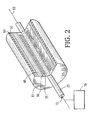
- FIG. 2 is a cut-away view of the rotor assembly of FIG. 1 .
- FIG. 3 is a perspective view of the rotor assembly of FIG. 2 with a banding surrounding a thermal reserve.
- FIG. 4 is a cross-sectional view of the rotor assembly of FIG. 2 with a thermal reserve segmented along the axis of the rotor.
- FIG. 5A is a depiction of an outer layer that is applied to the rotor assembly.
- FIG. 5B is a depiction of the aluminum portion of the outer layer shown in FIG. 5 A.
- FIG. 6 is a perspective view of the rotor assembly of FIG. 2 with the thermal reserve segmented normal to the axis of the rotor.
- a superconducting machine 10 for example, a motor or generator, includes a rotor assembly 15 and a stator assembly 20 concentrically arranged about rotor assembly 15 .
- rotor assembly 15 At the center 18 of rotor assembly 15 is a drive shaft 25 .
- Rotor assembly 15 is attached to drive shaft 25 to rotate with drive shaft 25 .
- Stator assembly 20 is stationary and includes a frame 45 and a stator winding 48 .
- Rotor assembly 15 includes a rotor winding support 30 concentrically arranged about drive shaft 25 and enclosing rotor winding 35 .
- Rotor winding 35 is made of a high temperature superconducting material of the type that operates in the temperature range of 20-40 K.
- Rotor winding 35 is made, for example, using the react-and-wind method, as known in the art, or using a wind-and-react method, as described in Manlief et al., U.S. Pat. No. 5,798,678, entitled “Superconducting Wind-and-React-Coils and Methods of Manufacture,” hereby incorporated by reference, or as described in Gamble et al., U.S. Pat. No. 5,777,420, entitled “Superconducting Synchronous Motor Construction,” hereby incorporated by reference.
- An AC flux shield 38 is concentrically arranged about winding support 30 preventing AC currents generated during motor transients from reaching rotor winding 35 .
- Rotor winding support 30 is made out of aluminum or other suitable structural material.
- Rotor winding support 30 acts as an AC flux shield if made from aluminum, copper, steel, or other electrically conductive material (for example, a material having an electrical resistivity of up to about 50 micro-ohms-cm), dispensing with the need to have a separate AC flux shield 38 as shown in FIG. 1 .
- thermal reserve 40 Concentrically arranged about winding support 30 is a thermal reserve 40 thermally coupled to rotor winding 35 by rotor winding support 30 .
- thermal reserve 40 Concentrically arranged around thermal reserve 40 is a banding 50 .
- Banding 50 secures thermal reserve 40 to rotor winding support 30 .
- banding 50 is formed from a metallic material, such as steel, which is segmented along a cross-sectional plane normal to axis 53 of rotor assembly 15 ; Segmentation of banding 50 is achieved by placing multiple individual bands (three are shown) around thermal reserve 40 .
- This structure electrically isolates each individual band 52 preventing current flow in a direction along axis 53 of rotor assembly 15 . The isolation is provided by a gap 55 between the individual bands.
- surrounding the banding is an outer layer 60 that shields rotor assembly 15 from heat generated by stator winding 48 .
- a refrigeration system for example, a cryocooler 70 operating with cold helium gas, for cooling rotor winding 35 during normal operation.
- Cold helium gas for cooling is fed through a port 72 in drive shaft 25 .
- Ducts (not shown) in a drive shaft 25 circulate the cold helium gas around rotor winding 35 to draw heat from rotor assembly 15 . Cooling is aided by the use of cooling channels in both winding support 30 and thermal reserve 40 .
- Thermal reserve 40 is thermally conductive, having a thermal conductivity sufficiently high to limit the temperature differential between thermal reserve 40 and winding 35 to some predetermined value. The predetermined value is dependent upon the specific application. In the disclosed embodiment, the thermal reserve has a sufficient thermal conductivity to limit the temperature differential at the boundary between thermal reserve 40 and winding 35 to at most, for example, not greater than about 10 K. Preferably, the differential will be less than 5 K. Even more preferably, the differential will be about 1 K. Thermal reserve 40 absorbs heat generated by rotor winding. 35 , decreasing the rate at which rotor winding 35 increases in temperature, prolonging the period in which rotor winding 35 remains within the superconducting temperature range.
- thermal reserve 40 is shown divided into five segments 80 along axis 53 of rotor assembly 15 .
- Each segment 80 is, for example, made of aluminum and is electrically isolated from the other segments by an electrically insulating material 85 made of, for example, metal oxides, epoxies, or Kapton®, a registered trademark of E. I. du Pont de Nemours and Company.
- the segmentation suppress eddy currents otherwise resulting from the fields produced by stator winding 48 . These eddy currents would produce heat losses in thermal is reserve 40 decreasing the efficiency of the machine and reducing the time of operation during cryocooler failure.
- the thermal reserve can be formed from ATTA®, availabe from Browne Technology, Inc., Brentwood, Tenn.
- ATTA® has a thermal conductivity (greater than about 400 W/m-K) better than copper while its elecctrical resistivity (500 micro-ohm-cm) is 200 times that of copper.
- ATTA® offers optimum properties of thermal and electrical conductivities for thermal reserve application.
- the material is avialable in 1-30 mil thick sheet or tape form and can be wrapped to fill the thermal reserve volume. There is no need for circumferential or axial segmentation of the thermal reserve.
- the additional operation time provided by thermal reserve 40 in the event of cryocooler failure is calculated by comparing the temperature increase of rotor winding combination 33 without thermal reserve 40 with rotor winding combination 33 surrounded by thermal reserve 40 .
- the field winding combination 33 has an inner radius R 1 , for example, 0.5 meters (the radius of drive shaft 25 ), an outer radius R 2 , for example, 0.53175 meters, and a length, for example, 0.6096 m.
- the volume of the field winding combination is:
- the heat capacity of winding combination 33 is determined by multiplying the volume of winding combination 33 by the specific heat and by the acceptable change in temperature.
- the acceptable change in temperature is determined by subtracting the normal operating temperature of rotor winding 35 from the maximum operating temperature, which is the quench temperature of rotor winding 35 decreased for some margin of safety. Typically, this maximum operating temperature will be 5 K above the normal operating temperature.
- Thermal reserve 40 is, for example, constructed from aluminum and has a thickness, t, of 0.0381 m.
- the volume of thermal reserve 40 is:
- thermal reserve 40 keeps the high temperature superconducting machine in operation for more than one and a half additional hours. During this additional time, a repair crew notified of the refrigeration system failure can much more likely repair or replace the refrigeration system, keeping the machine in operation.
- outer layer 60 is composed of a multi-layer insulation, made of an interior layer 64 attached to a thin strong exterior layer material 66 .
- Interior layer 64 is made of, for example, many layers of aluminized mylar.
- Surronding interior layer 64 is an exterior layer 66 , preferably ⁇ fraction (1/16) ⁇ inch thick, of Kevlar or other strong material, such as steel, a composite of G 10 materials, or fiber reenforced epoxies.
- the aluminum of interior layer 64 is segmented with slots 68 . Slots 68 are arranged so eddy currents are suppressed.
- stator winding 48 is made of conventional nonsuperconducting wire and is water cooled by the inclusion of cooling tubes (not shown) both interwound with stator winding 48 and enclosed within frame 45 . There is sufficient increase in efficiency, power transfer, and size reduction with the rotor winding alone being made of a superconducting material.
- Frame 45 is made of any suitable strong material, such as steel.
- thermal reserve 40 can be divided into 8, 10, or even more segments.
- thermal reserve 40 is segmented normal to axis 53 to prevent the flow of currents in the direction along the axis of the rotor, but segment-free along axis 53 .
- Thick disks of material 100 are aligned along axis 53 and each disk 100 is concentrically arranged about winding combination 33 .
- Each disk 100 is electrically isolated from the others by an insulating material 105 .
- each disk 100 is made of aluminum and may be shrunk fit over the winding combination 33 .
- the ease of construction of the rotor of FIG. 6 outweighs the losses generated by not segmenting the aluminum in a direction along the axis of the rotor. It may also be desirable in certain applications to segment thermal reserve 40 in the directions both normal to and along axis 53 of the rotor in order to suppress both axial and normal currents.
- thermal reserve 40 is made of an electrically nonconductive material, for example, beryllium oxide or alumina.
- an electrically nonconductive material prevents eddy currents from being generated in thermal reserve 40 .
- banding 50 is modified by inserting a nonconductive material between the individual conductive bands.
- a nonconductive material of sufficient strength such as Kevlar, glass filaments or fibers, or any other high-strength electrically nonconductive material
- the nonconductive material also acts as a banding.
- banding 50 is made entirely of nonconductive materials.
- exterior layer 66 of outer layer 60 is of sufficient strength to also serve as banding 50 .
- exterior layer 66 is provided with a greater thickness than would otherwise be necessary to secure outer layer 60 alone to rotor assembly 15 .
- Exterior layer 66 can also be segmented normal to axis 53 of rotor assembly 15 .
- rotor winding support 30 is made of an electrically nonconductive material.
Abstract
A high temperature superconducting rotor for a synchronous machine includes a high temperature superconducting field winding, a field winding support concentrically arranged about the high temperature superconducting field winding, and a thermal reserve concentrically arranged about the field winding support. The thermal reserve is thermally coupled to the field winding to maintain a temperature differential between the thermal reserve and the field winding not greater than about 10 K.
Description
This is a CIP of application Ser. No. 09/251,310, filed Feb. 17, 1999, now U.S. Pat. No. 6,140,719.
This invention relates to a high temperature superconducting rotor for a synchronous machine.
Typically, a superconducting winding of the rotor in a superconducting machine is cooled with a cryogenic refrigeration system. In the event of a refrigeration system failure, the superconducting winding will heat and eventually quench, leading to total machine failure.
A rotor having a thermal reserve arranged about a high temperature superconducting (HTS) winding is provided. In the event of a refrigeration system failure, the thermal reserve absorbs thermal energy from the HTS winding, thereby reducing the rate of increase of the temperature of the superconducting winding.
In accordance with one aspect of the invention, a high temperature superconducting rotor is provided including a high temperature superconducting field winding, a field winding support concentrically arranged about the high temperature superconducting field winding, and a thermal reserve concentrically arranged about the field winding support. The thermally reserve is coupled to the field winding to maintain a temperature differential between the thermal reserve and the field winding not greater than about 10 K.
Embodiments of this aspect of the invention may include one or more of the following features.
The thermal reserve includes a thermally conductive material. The material is electrically conductive, for example, aluminum or ATTA®. The material includes segmentation normal to the rotor axis, along the rotor axis, or both. The material, for example, aluminum, is shrunk fit over the field winding support.
Alternatively, the thermal reserve includes a material that is electrically nonconductive, for example, a ceramic, including beryllium oxide or alumina.
The rotor includes a banding concentrically arranged about the thermal reserve. The banding includes an electrically conductive material, for example, steel, an electrically nonconductive material, for example, Kevlar or glass fiber, or both. The banding includes segmentation normal to the rotor axis.
The rotor includes an outer layer concentrically arranged about the thermal reserve. The outer layer includes a thermally nonconductive material. The outer layer includes either electrically conductive materials, electrically nonconductive materials, or both. Electrically conductive materials in the outer layer are configured to prevent the flow of eddy currents; for example, a layer of aluminum coated mylar is used. The aluminum coating includes segments. A banding is concentrically arranged about the outer layer.
In accordance with another aspect of the invention, a superconducting machine has a rotor. The rotor includes a high temperature superconducting field winding and a field winding support for securing the field winding. The support is electrically isolated from the field winding. An AC flux shield is concentrically arranged about the field winding. A thermal reserve is concentrically arranged about the AC flux shield and thermally coupled to the field winding to maintain a temperature differential between the thermal reserve and the field winding not greater than about 10 K. The machine further includes a stator concentrically arranged about the rotor.
In accordance with an embodiment of this aspect of the invention, a cryogenic refrigeration system is thermally coupled to the rotor.
In accordance with another aspect of the invention, a method is provided for limiting the rate of increase in the temperature of a superconducting winding. The method includes concentrically arranging a thermal reserve about and in thermal contact with the superconducting winding, and maintaining a temperature diferrential between the thermal reserve and the field winding no greater than about 10 K.
Embodiments of this aspect of the invention may include one or more of the following features.
The invention includes within the thermal reserve a thermally conducting material. Within the thermal reserve, an electrically nonconductive material is disposed between segments of an electrically conductive material. Within the thermal reserve, configuring the electrically nonconductive material to suppress eddy currents. The invention further includes concentrically arranging a thermally nonconductive material about the thermally conductive material.
According to another aspect of the invention, a high temperature superconducting rotor includes a high temperature superconducting field winding, a field winding support concentrically arranged about the high temperature superconductor field winding, and a thermal reserve concentrically arranged about the field winding support. The thermal reserve includes ATTA® which is thermally conductive and electrically nonconductive.
FIG. 1 is a diagrammatic illustration of the rotor and stator assemblies of a superconducting machine.
FIG. 2 is a cut-away view of the rotor assembly of FIG. 1.
FIG. 3 is a perspective view of the rotor assembly of FIG. 2 with a banding surrounding a thermal reserve.
FIG. 4 is a cross-sectional view of the rotor assembly of FIG. 2 with a thermal reserve segmented along the axis of the rotor.
FIG. 5A is a depiction of an outer layer that is applied to the rotor assembly.
FIG. 5B is a depiction of the aluminum portion of the outer layer shown in FIG. 5A.
FIG. 6 is a perspective view of the rotor assembly of FIG. 2 with the thermal reserve segmented normal to the axis of the rotor.
Referring to FIG. 1, a superconducting machine 10, for example, a motor or generator, includes a rotor assembly 15 and a stator assembly 20 concentrically arranged about rotor assembly 15. At the center 18 of rotor assembly 15 is a drive shaft 25. Rotor assembly 15 is attached to drive shaft 25 to rotate with drive shaft 25. Stator assembly 20 is stationary and includes a frame 45 and a stator winding 48.
An AC flux shield 38 is concentrically arranged about winding support 30 preventing AC currents generated during motor transients from reaching rotor winding 35.
Referring also to FIG. 2, rotor winding support 30 is made out of aluminum or other suitable structural material. Rotor winding support 30 acts as an AC flux shield if made from aluminum, copper, steel, or other electrically conductive material (for example, a material having an electrical resistivity of up to about 50 micro-ohms-cm), dispensing with the need to have a separate AC flux shield 38 as shown in FIG. 1.
Concentrically arranged about winding support 30 is a thermal reserve 40 thermally coupled to rotor winding 35 by rotor winding support 30. Concentrically arranged around thermal reserve 40 is a banding 50. Banding 50 secures thermal reserve 40 to rotor winding support 30.
Referring to FIG. 3, banding 50 is formed from a metallic material, such as steel, which is segmented along a cross-sectional plane normal to axis 53 of rotor assembly 15; Segmentation of banding 50 is achieved by placing multiple individual bands (three are shown) around thermal reserve 40. This structure electrically isolates each individual band 52 preventing current flow in a direction along axis 53 of rotor assembly 15. The isolation is provided by a gap 55 between the individual bands. Referring again to FIG. 2, surrounding the banding is an outer layer 60 that shields rotor assembly 15 from heat generated by stator winding 48.
Connected to drive shaft 25 is a refrigeration system, for example, a cryocooler 70 operating with cold helium gas, for cooling rotor winding 35 during normal operation. Cold helium gas for cooling is fed through a port 72 in drive shaft 25. Ducts (not shown) in a drive shaft 25 circulate the cold helium gas around rotor winding 35 to draw heat from rotor assembly 15. Cooling is aided by the use of cooling channels in both winding support 30 and thermal reserve 40.
In the event of cryocooler failure, heat buildup in rotor winding 35 causes rotor winding 35 to lose its superconducting characteristics. The rate of heat buildup is reduced, however, by thermal reserve 40. Thermal reserve 40 is thermally conductive, having a thermal conductivity sufficiently high to limit the temperature differential between thermal reserve 40 and winding 35 to some predetermined value. The predetermined value is dependent upon the specific application. In the disclosed embodiment, the thermal reserve has a sufficient thermal conductivity to limit the temperature differential at the boundary between thermal reserve 40 and winding 35 to at most, for example, not greater than about 10 K. Preferably, the differential will be less than 5 K. Even more preferably, the differential will be about 1 K. Thermal reserve 40 absorbs heat generated by rotor winding. 35, decreasing the rate at which rotor winding 35 increases in temperature, prolonging the period in which rotor winding 35 remains within the superconducting temperature range.
Referring to FIG. 4 (in which for ease of discussion, rotor winding 35 and rotor winding support 30 are illustrated as a single structure—rotor winding combination 33), thermal reserve 40 is shown divided into five segments 80 along axis 53 of rotor assembly 15. Each segment 80 is, for example, made of aluminum and is electrically isolated from the other segments by an electrically insulating material 85 made of, for example, metal oxides, epoxies, or Kapton®, a registered trademark of E. I. du Pont de Nemours and Company. The segmentation suppress eddy currents otherwise resulting from the fields produced by stator winding 48. These eddy currents would produce heat losses in thermal is reserve 40 decreasing the efficiency of the machine and reducing the time of operation during cryocooler failure.
Alternatively, the thermal reserve can be formed from ATTA®, availabe from Browne Technology, Inc., Brentwood, Tenn. ATTA® has a thermal conductivity (greater than about 400 W/m-K) better than copper while its elecctrical resistivity (500 micro-ohm-cm) is 200 times that of copper. ATTA® offers optimum properties of thermal and electrical conductivities for thermal reserve application. The material is avialable in 1-30 mil thick sheet or tape form and can be wrapped to fill the thermal reserve volume. There is no need for circumferential or axial segmentation of the thermal reserve.
The additional operation time provided by thermal reserve 40 in the event of cryocooler failure is calculated by comparing the temperature increase of rotor winding combination 33 without thermal reserve 40 with rotor winding combination 33 surrounded by thermal reserve 40.
The field winding combination 33 has an inner radius R1, for example, 0.5 meters (the radius of drive shaft 25), an outer radius R2, for example, 0.53175 meters, and a length, for example, 0.6096 m. The volume of the field winding combination is:
If field winding support 30 is made of aluminum, the specific heat of field winding combination 33 can be roughly approximated as equal to the specific heat of aluminum, which at 25 K is: 
The heat capacity of winding combination 33 is determined by multiplying the volume of winding combination 33 by the specific heat and by the acceptable change in temperature. The acceptable change in temperature is determined by subtracting the normal operating temperature of rotor winding 35 from the maximum operating temperature, which is the quench temperature of rotor winding 35 decreased for some margin of safety. Typically, this maximum operating temperature will be 5 K above the normal operating temperature. The heat capacity of winding combination 33 under these conditions is: 
The operating time following cryocooler failure is calculated by dividing the heat capacity of rotor winding combination 33 by the power loss in the field winding. Once this time is reached, the power loss will have heated the winding combination 33 to the maximum acceptable operating temperature. Typically, a superconducting machine will have a power loss in the superconducting winding of 25 watts, resulting in an operating time after cryocooler failure of 1.22 hours. 
The operating time after cryocooler failure will now be calculated with the addition of thermal reserve 40. Thermal reserve 40 is, for example, constructed from aluminum and has a thickness, t, of 0.0381 m. The volume of thermal reserve 40 is:
The heat capacity of thermal reserve 40 is the volume multiplied by the specific heat of the material used, in this example, aluminum: 
Assuming the same 25 watt loss in field winding 35 as in the prior example, but this time adding together the heat capacities of rotor winding combination 33 and thermal reserve 40 with the preferred thermal conductivity, the operation time available following a cryogenic refrigeration failure is: 
Accordingly, the use of thermal reserve 40 with the indicated dimensions keeps the high temperature superconducting machine in operation for more than one and a half additional hours. During this additional time, a repair crew notified of the refrigeration system failure can much more likely repair or replace the refrigeration system, keeping the machine in operation.
Referring to FIG. 5B, the aluminum of interior layer 64 is segmented with slots 68. Slots 68 are arranged so eddy currents are suppressed.
Referring again to FIG. 1, stator winding 48 is made of conventional nonsuperconducting wire and is water cooled by the inclusion of cooling tubes (not shown) both interwound with stator winding 48 and enclosed within frame 45. There is sufficient increase in efficiency, power transfer, and size reduction with the rotor winding alone being made of a superconducting material. Frame 45 is made of any suitable strong material, such as steel.
Alternative embodiments are within the scope of the following claims. For example, thermal reserve 40 can be divided into 8, 10, or even more segments. In yet another alternative embodiment, shown in FIG. 6, thermal reserve 40 is segmented normal to axis 53 to prevent the flow of currents in the direction along the axis of the rotor, but segment-free along axis 53. Thick disks of material 100 are aligned along axis 53 and each disk 100 is concentrically arranged about winding combination 33. Each disk 100 is electrically isolated from the others by an insulating material 105. For example, each disk 100 is made of aluminum and may be shrunk fit over the winding combination 33.
In certain circumstances, the ease of construction of the rotor of FIG. 6 outweighs the losses generated by not segmenting the aluminum in a direction along the axis of the rotor. It may also be desirable in certain applications to segment thermal reserve 40 in the directions both normal to and along axis 53 of the rotor in order to suppress both axial and normal currents.
In yet another embodiment, thermal reserve 40 is made of an electrically nonconductive material, for example, beryllium oxide or alumina. The use of an electrically nonconductive material prevents eddy currents from being generated in thermal reserve 40.
In other embodiments, banding 50 is modified by inserting a nonconductive material between the individual conductive bands. By providing a nonconductive material of sufficient strength, such as Kevlar, glass filaments or fibers, or any other high-strength electrically nonconductive material, the nonconductive material also acts as a banding. Alternatively, banding 50 is made entirely of nonconductive materials.
In yet other embodiments, exterior layer 66 of outer layer 60 is of sufficient strength to also serve as banding 50. In this case, exterior layer 66 is provided with a greater thickness than would otherwise be necessary to secure outer layer 60 alone to rotor assembly 15. Exterior layer 66 can also be segmented normal to axis 53 of rotor assembly 15.
In other embodiments, rotor winding support 30 is made of an electrically nonconductive material.
Claims (26)
1. A high temperature superconducting rotor, comprising:
a high temperature superconducting field winding,
a field winding support concentrically arranged on the high temperature superconductor field winding, and
a thermal reserve concentrically arranged on the field winding support, the thermal reserve configured to absorb heat from the field winding to maintain a temperature differential between the thermal reserve and the field winding not greater than about 10 K.
2. The rotor of claim 1 wherein the thermal reserve comprises a material that is thermally conductive.
3. The rotor of claim 1 wherein the thermal reserve comprises a ceramic material.
4. The rotor of claim 1 wherein the thermal reserve comprises Alumina.
5. The rotor of claim 1 wherein the thermal reserve comprises ATTA®.
6. The rotor of claim 1 wherein the thermal reserve comprises Beryllium Oxide.
7. The rotor of claim 1 further comprising a banding concentrically arranged about the thermal reserve.
8. The rotor of claim 7 wherein the banding comprises an electrically conductive material.
9. The rotor of claim 8 wherein the electrically conductive material includes segmentation in a direction normal to the axis of the rotor.
10. The rotor of claim 7 wherein the banding comprises an electrically nonconductive material.
11. The rotor of claim 10 wherein the banding comprises Kevlar.
12. The rotor of claim 10 wherein the banding comprises glass fiber.
13. The rotor of claim 1 further comprising an outer layer concentrically arranged about the thermal reserve, the outer layer comprising a thermally non-conductive material.
14. The rotor of claim 13 wherein the outer layer comprises an electrically nonconductive material.
15. The rotor of claim 13 wherein the outer layer comprises an electrically conductive material.
16. The rotor of claim 15 wherein the electrically conductive material is configured to prevent the flow of eddy currents within the electrically conductive material.
17. The rotor of claim 16 wherein the outer layer comprises multiple layers of aluminum coated mylar.
18. The rotor of claim 17 wherein the aluminum coating includes segments whereby electric current does not flow in a direction along the axis of the rotor.
19. The rotor of claim 13 further comprising a banding concentrically arranged about the outer layer.
20. The high temperature superconducting rotor of claim 1 , wherein the thermal reserve contacts the winding support.
21. A method of limiting the rate of increase in the temperature of a superconducting winding, comprising:
concentrically arranging a thermal reserve on and in thermal contact with the superconducting winding,
the thermal reserve absorbing heat from the superconducting winding; and
maintaining a temperature differential between the thermal reserve and the field winding no greater than about 10 K.
22. The method of claim 21 wherein the thermal reserve comprises a thermally conducting material.
23. The method of claim 22 further comprising:
concentrically arranging a thermally nonconductive material about the thermally conductive material.
24. The method of claim 21 further comprising:
configuring the thermal reserve to suppress electric eddy currents from flowing about the superconducting winding.
25. The method of claim 21 further comprising supporting the superconducting windings with a winding support, the thermal reserve contacting the winding support.
26. A high temperature superconducting rotor, comprising: a high temperature superconducting field winding,
a field winding support concentrically arranged about the high temperature superconductor field winding, and
a thermal reserve concentrically arranged about the field winding support, the thermal reserve including ATTA® which is thermally conductive and electrically nonconductive.
Priority Applications (1)
| Application Number | Priority Date | Filing Date | Title |
|---|---|---|---|
| US09/696,363 US6768232B1 (en) | 1999-02-17 | 2000-10-25 | High temperature superconductor rotor for a synchronous machine |
Applications Claiming Priority (2)
| Application Number | Priority Date | Filing Date | Title |
|---|---|---|---|
| US09/251,310 US6140719A (en) | 1999-02-17 | 1999-02-17 | High temperature superconducting rotor for a synchronous machine |
| US09/696,363 US6768232B1 (en) | 1999-02-17 | 2000-10-25 | High temperature superconductor rotor for a synchronous machine |
Related Parent Applications (1)
| Application Number | Title | Priority Date | Filing Date |
|---|---|---|---|
| US09/251,310 Continuation-In-Part US6140719A (en) | 1999-02-17 | 1999-02-17 | High temperature superconducting rotor for a synchronous machine |
Publications (1)
| Publication Number | Publication Date |
|---|---|
| US6768232B1 true US6768232B1 (en) | 2004-07-27 |
Family
ID=22951394
Family Applications (2)
| Application Number | Title | Priority Date | Filing Date |
|---|---|---|---|
| US09/251,310 Expired - Lifetime US6140719A (en) | 1999-02-17 | 1999-02-17 | High temperature superconducting rotor for a synchronous machine |
| US09/696,363 Expired - Fee Related US6768232B1 (en) | 1999-02-17 | 2000-10-25 | High temperature superconductor rotor for a synchronous machine |
Family Applications Before (1)
| Application Number | Title | Priority Date | Filing Date |
|---|---|---|---|
| US09/251,310 Expired - Lifetime US6140719A (en) | 1999-02-17 | 1999-02-17 | High temperature superconducting rotor for a synchronous machine |
Country Status (3)
| Country | Link |
|---|---|
| US (2) | US6140719A (en) |
| AU (1) | AU3601000A (en) |
| WO (1) | WO2000049703A1 (en) |
Cited By (3)
| Publication number | Priority date | Publication date | Assignee | Title |
|---|---|---|---|---|
| US20100289350A1 (en) * | 2009-05-14 | 2010-11-18 | Naoki Watanabe | Cooling mechanism for axial gap type rotating machines |
| US20140028303A1 (en) * | 2012-07-27 | 2014-01-30 | Abb Technology Ag | Device for measuring the direct component of alternating current |
| EP3291429A1 (en) | 2016-08-30 | 2018-03-07 | Gamesa Innovation & Technology, S.L. | Synchronous generator for wind turbines |
Families Citing this family (38)
| Publication number | Priority date | Publication date | Assignee | Title |
|---|---|---|---|---|
| US6140719A (en) * | 1999-02-17 | 2000-10-31 | American Superconductor Corporation | High temperature superconducting rotor for a synchronous machine |
| US6597082B1 (en) * | 2000-08-04 | 2003-07-22 | American Superconductor Corporation | HTS superconducting rotating machine |
| US6460346B1 (en) * | 2000-08-30 | 2002-10-08 | General Electric Company | Method and system for identifying malfunctioning combustion chambers in a gas turbine |
| US6605885B2 (en) | 2001-05-15 | 2003-08-12 | General Electric Company | Super-conducting rotor coil support with tension rods and bolts |
| US6608409B2 (en) | 2001-05-15 | 2003-08-19 | General Electric Company | High temperature super-conducting rotor having a vacuum vessel and electromagnetic shield and an assembly method |
| US6590308B2 (en) | 2001-05-15 | 2003-07-08 | General Electric Company | High power density super-conducting electric machine |
| US6590305B2 (en) | 2001-05-15 | 2003-07-08 | General Electric Company | High temperature super-conducting synchronous rotor having an electromagnetic shield and method for assembly |
| US6727633B2 (en) | 2001-05-15 | 2004-04-27 | General Electric Company | High temperature super-conducting synchronous rotor coil support with tension rods and method for assembly of the coil support |
| US6787967B2 (en) | 2001-05-15 | 2004-09-07 | General Electric Company | High temperature super-conducting rotor coil support and coil support method |
| US6803684B2 (en) | 2001-05-15 | 2004-10-12 | General Electric Company | Super-conducting synchronous machine having rotor and a plurality of super-conducting field coil windings |
| US6922885B2 (en) | 2001-05-15 | 2005-08-02 | General Electric Company | High temperature superconducting racetrack coil |
| US6577028B2 (en) | 2001-05-15 | 2003-06-10 | General Electric Company | High temperature superconducting rotor power leads |
| US6570292B2 (en) | 2001-05-15 | 2003-05-27 | General Electric Company | High temperature super-conducting rotor coil support with split coil housing and assembly method |
| US6553773B2 (en) | 2001-05-15 | 2003-04-29 | General Electric Company | Cryogenic cooling system for rotor having a high temperature super-conducting field winding |
| US6617714B2 (en) | 2001-05-15 | 2003-09-09 | General Electric Company | High temperature super-conducting coils supported by an iron core rotor |
| US6605886B2 (en) | 2001-07-31 | 2003-08-12 | General Electric Company | High temperature superconductor synchronous rotor coil support insulator |
| US6703729B2 (en) * | 2001-08-15 | 2004-03-09 | General Electric Company | Reverse flow stator ventilation system for superconducting synchronous machine |
| US6795720B2 (en) * | 2001-08-24 | 2004-09-21 | General Electric Company | High temperature superconducting synchronous rotor coil having multi-piece rotor core |
| US6791229B2 (en) * | 2001-09-17 | 2004-09-14 | Osman K. Mawardi | Thin film superconducting motor with magnetically-quenched rotor |
| US6710497B2 (en) * | 2001-10-16 | 2004-03-23 | General Electric Company | Apparatus and method for a field winding assembly mountable on a rotor in a synchronous machine |
| JP3775328B2 (en) * | 2002-03-27 | 2006-05-17 | 三菱電機株式会社 | Synchronous induction motor rotor, compressor, synchronous induction motor rotor manufacturing method, synchronous induction motor rotor mold |
| FR2844933B1 (en) * | 2002-09-20 | 2004-11-26 | Sagem | IMPROVEMENTS ON HIGH POWER MOTORS. |
| US6794792B2 (en) * | 2002-11-13 | 2004-09-21 | General Electric Company | Cold structural enclosure for multi-pole rotor having super-conducting field coil windings. |
| DE10259822B4 (en) * | 2002-12-19 | 2009-01-02 | Siemens Ag | Electric machine with bandaged, deep-cooling winding |
| US6725683B1 (en) | 2003-03-12 | 2004-04-27 | General Electric Company | Cryogenic cooling system for rotor having a high temperature super-conducting field winding |
| US7547999B2 (en) * | 2003-04-28 | 2009-06-16 | General Electric Company | Superconducting multi-pole electrical machine |
| US7185501B2 (en) * | 2004-12-16 | 2007-03-06 | General Electric Company | Cryogenic cooling system and method with backup cold storage device |
| US7791229B2 (en) * | 2008-04-02 | 2010-09-07 | Goodzeit Carl L | Low heat leak, high torque power shaft for cryogenic machines |
| US8310123B2 (en) | 2008-07-28 | 2012-11-13 | Direct Drive Systems, Inc. | Wrapped rotor sleeve for an electric machine |
| US8084909B2 (en) * | 2009-04-09 | 2011-12-27 | Goodzeit Carl L | Dual armature motor/generator with flux linkage |
| US7843094B2 (en) * | 2009-04-09 | 2010-11-30 | Goodzeit Carl L | Dual armature motor/generator with flux linkage between dual armatures and a superconducting field coil |
| US8710944B2 (en) * | 2010-05-25 | 2014-04-29 | General Electric Company | Superconducting magnetizer |
| DE102011077054A1 (en) | 2011-06-07 | 2012-12-13 | Siemens Aktiengesellschaft | Rotor for an electric machine and electric machine |
| CN102594088A (en) * | 2012-03-15 | 2012-07-18 | 西南交通大学 | Cylinder type synchronous linear motor with superconducting magnet magnetic pole |
| US9819248B2 (en) | 2012-12-31 | 2017-11-14 | Teco-Westinghouse Motor Company | Assemblies and methods for cooling electric machines |
| WO2018109237A1 (en) | 2016-12-12 | 2018-06-21 | Andrades Lago Enrique | Rotary electrical machine |
| US10601299B2 (en) * | 2017-09-07 | 2020-03-24 | American Superconductor Corporation | High temperature superconductor generator with increased rotational inertia |
| US10669001B2 (en) | 2017-12-11 | 2020-06-02 | American Superconductor Corporation | Hybrid electrical and mechanical propulsion and energy system for a ship |
Citations (15)
| Publication number | Priority date | Publication date | Assignee | Title |
|---|---|---|---|---|
| US3956648A (en) * | 1974-11-13 | 1976-05-11 | Massachusetts Institute Of Technology | Superconducting machine having flexible shield means operable to protect the superconducting field winding against transients |
| US4016444A (en) * | 1974-04-17 | 1977-04-05 | Societe Generale De Constructions Electriques Et Mecaniques (Alsthom) | Rotor for an electric machine having a cryo-inductor |
| US4039870A (en) * | 1975-07-17 | 1977-08-02 | Westinghouse Electric Corporation | Integrated annular supporting structure and damper shield for superconducting rotor assembly of dynamoelectric machine |
| US4063122A (en) * | 1974-04-16 | 1977-12-13 | Siemens Aktiengesellschaft | Rotor containing a field winding cooled to a low temperature |
| US4152609A (en) * | 1976-10-22 | 1979-05-01 | Westinghouse Electric Corp. | Rotor member for superconducting generator |
| US4174483A (en) | 1976-11-30 | 1979-11-13 | Filippov Iosif F | Cryogenically cooled electrical machine |
| US4204134A (en) * | 1977-03-29 | 1980-05-20 | Kraftwerk Union Aktiengesellschaft | Coolant loop for the rotor of a turbogenerator with a superconductive exciter winding |
| US4208598A (en) * | 1978-05-10 | 1980-06-17 | Badrukhin Jury I | Electrical machine with cryogenic cooling |
| US4267473A (en) * | 1976-11-23 | 1981-05-12 | Electric Power Research Institute | Superconducting generator thermal radiation shield having substantially uniform temperature |
| US4277705A (en) * | 1977-09-02 | 1981-07-07 | Electric Power Research Institute | Method and apparatus for cooling a winding in the rotor of an electrical machine |
| US4365175A (en) | 1980-09-29 | 1982-12-21 | Electric Power Research Institute, Inc. | Fast starting cold shield cooling circuit for superconducting generators |
| US4386289A (en) * | 1980-06-02 | 1983-05-31 | Siemens Aktiengesellschaft | Device for cooling a superconducting field winding and a damper shield of the rotor of an electric machine |
| US5066638A (en) * | 1990-09-10 | 1991-11-19 | Emerson Electric Co. | Superconducting motor with multiple winding rotor |
| US5777420A (en) * | 1996-07-16 | 1998-07-07 | American Superconductor Corporation | Superconducting synchronous motor construction |
| US6140719A (en) * | 1999-02-17 | 2000-10-31 | American Superconductor Corporation | High temperature superconducting rotor for a synchronous machine |
-
1999
- 1999-02-17 US US09/251,310 patent/US6140719A/en not_active Expired - Lifetime
-
2000
- 2000-02-17 AU AU36010/00A patent/AU3601000A/en not_active Abandoned
- 2000-02-17 WO PCT/US2000/004298 patent/WO2000049703A1/en active Application Filing
- 2000-10-25 US US09/696,363 patent/US6768232B1/en not_active Expired - Fee Related
Patent Citations (15)
| Publication number | Priority date | Publication date | Assignee | Title |
|---|---|---|---|---|
| US4063122A (en) * | 1974-04-16 | 1977-12-13 | Siemens Aktiengesellschaft | Rotor containing a field winding cooled to a low temperature |
| US4016444A (en) * | 1974-04-17 | 1977-04-05 | Societe Generale De Constructions Electriques Et Mecaniques (Alsthom) | Rotor for an electric machine having a cryo-inductor |
| US3956648A (en) * | 1974-11-13 | 1976-05-11 | Massachusetts Institute Of Technology | Superconducting machine having flexible shield means operable to protect the superconducting field winding against transients |
| US4039870A (en) * | 1975-07-17 | 1977-08-02 | Westinghouse Electric Corporation | Integrated annular supporting structure and damper shield for superconducting rotor assembly of dynamoelectric machine |
| US4152609A (en) * | 1976-10-22 | 1979-05-01 | Westinghouse Electric Corp. | Rotor member for superconducting generator |
| US4267473A (en) * | 1976-11-23 | 1981-05-12 | Electric Power Research Institute | Superconducting generator thermal radiation shield having substantially uniform temperature |
| US4174483A (en) | 1976-11-30 | 1979-11-13 | Filippov Iosif F | Cryogenically cooled electrical machine |
| US4204134A (en) * | 1977-03-29 | 1980-05-20 | Kraftwerk Union Aktiengesellschaft | Coolant loop for the rotor of a turbogenerator with a superconductive exciter winding |
| US4277705A (en) * | 1977-09-02 | 1981-07-07 | Electric Power Research Institute | Method and apparatus for cooling a winding in the rotor of an electrical machine |
| US4208598A (en) * | 1978-05-10 | 1980-06-17 | Badrukhin Jury I | Electrical machine with cryogenic cooling |
| US4386289A (en) * | 1980-06-02 | 1983-05-31 | Siemens Aktiengesellschaft | Device for cooling a superconducting field winding and a damper shield of the rotor of an electric machine |
| US4365175A (en) | 1980-09-29 | 1982-12-21 | Electric Power Research Institute, Inc. | Fast starting cold shield cooling circuit for superconducting generators |
| US5066638A (en) * | 1990-09-10 | 1991-11-19 | Emerson Electric Co. | Superconducting motor with multiple winding rotor |
| US5777420A (en) * | 1996-07-16 | 1998-07-07 | American Superconductor Corporation | Superconducting synchronous motor construction |
| US6140719A (en) * | 1999-02-17 | 2000-10-31 | American Superconductor Corporation | High temperature superconducting rotor for a synchronous machine |
Non-Patent Citations (4)
| Title |
|---|
| B. Gamble and J. Goldman, "High Temperature Superconducting Motor and Generators for Submarines and Surface Ships." Naval Symposium on Electric Machines, Newport, RI, Jul. 28-31, 1997. |
| D. Aized, B.B. Gamble, A. Sidi-Yekhlef and J.P. Voccio, D.I. Driscoll, B.A. Shoykhet and B.X. Zhang, "Status of the 1.000 hp HTS Motor Development." 1998 Applied Superconductivity Conference, Palm Desert CA, Sep. 14-18, 1998. |
| J.W. Lue, M.S. Lubell, D. Aized, J.M. Campbell and R.E. Schwall "Quenches in a high-temperature superconducting tape and pancake coil." Cryogenics 36 (1996), 379-389. |
| R. Schifert, B. Zhang, LB. Shoykhet, D. Driscoll, A. Meyer, J. Zevchek and E. Johnson, B. Gamble, C. Prum, J. Voccio, H. Picard, "High Temperature Superconducting Synchronous Motor Design and Test." Power Conference, Apr. 1996. |
Cited By (5)
| Publication number | Priority date | Publication date | Assignee | Title |
|---|---|---|---|---|
| US20100289350A1 (en) * | 2009-05-14 | 2010-11-18 | Naoki Watanabe | Cooling mechanism for axial gap type rotating machines |
| US8390157B2 (en) * | 2009-05-14 | 2013-03-05 | Shin-Etsu Chemical Co., Ltd. | Cooling mechanism for axial gap type rotating machines |
| US20140028303A1 (en) * | 2012-07-27 | 2014-01-30 | Abb Technology Ag | Device for measuring the direct component of alternating current |
| US9279836B2 (en) * | 2012-07-27 | 2016-03-08 | Abb Technology Ag | Device for measuring the direct component of alternating current |
| EP3291429A1 (en) | 2016-08-30 | 2018-03-07 | Gamesa Innovation & Technology, S.L. | Synchronous generator for wind turbines |
Also Published As
| Publication number | Publication date |
|---|---|
| AU3601000A (en) | 2000-09-04 |
| WO2000049703A1 (en) | 2000-08-24 |
| US6140719A (en) | 2000-10-31 |
| WO2000049703A8 (en) | 2001-05-10 |
| WO2000049703A9 (en) | 2001-11-22 |
Similar Documents
| Publication | Publication Date | Title |
|---|---|---|
| US6768232B1 (en) | High temperature superconductor rotor for a synchronous machine | |
| US6489701B1 (en) | Superconducting rotating machines | |
| US7423356B2 (en) | Thermally-conductive stator support structure | |
| US8212437B2 (en) | Superconducting multi-pole electrical machine | |
| US7119644B2 (en) | Mounting structure for superconducting windings | |
| US6879081B1 (en) | Stator coil assembly for superconducting rotating machines | |
| JP4247273B2 (en) | Machine with rotor and superconducting rotor winding | |
| US6911759B2 (en) | Stator coil assembly for superconducting rotating machines | |
| US3745389A (en) | Supercooled dynamo electric machines | |
| WO2004102769A2 (en) | Homopolar machine with shaft axial thrust compensation for reduced thrust bearing wear and noise | |
| JPS648538B2 (en) | ||
| US20180062484A1 (en) | Synchronous generator for wind turbine | |
| WO2007083873A1 (en) | Superconducting cable | |
| US4126798A (en) | Superconductive winding | |
| MXPA02004837A (en) | High temperature super-conducting rotor having a vacuum vessel and electromagnetic shield and an assembly method. | |
| MXPA02004838A (en) | High temperature super-conducting rotor coil support with split coil housing and assembly method. | |
| JP5043955B2 (en) | Superconducting synchronous motor | |
| US6628033B1 (en) | Reduction of induced magnetic forces on current collectors in homopolar machines having high magnetic fields | |
| EP2817871B1 (en) | Superconducting rotating electrical machine and manufacturing method for high temperature superconducting film thereof | |
| Kirtley et al. | MIT-EEI program on large superconducting machines | |
| JP2001093721A (en) | High-temperature superconducting magnet | |
| US6577028B2 (en) | High temperature superconducting rotor power leads | |
| Singh et al. | Conceptual design of a high temperature superconducting generator | |
| KR20020087355A (en) | High temperature super-conducting rotor coil support and coil support method | |
| Gamble et al. | High-power-density superconducting generator |
Legal Events
| Date | Code | Title | Description |
|---|---|---|---|
| AS | Assignment |
Owner name: AMERICAN SUPERCONDUCTOR CORPORATION, MASSACHUSETTS Free format text: ASSIGNMENT OF ASSIGNORS INTEREST;ASSIGNOR:KALSI, SWARN S.;REEL/FRAME:011502/0204 Effective date: 20010124 |
|
| CC | Certificate of correction | ||
| FPAY | Fee payment |
Year of fee payment: 4 |
|
| REMI | Maintenance fee reminder mailed | ||
| FPAY | Fee payment |
Year of fee payment: 8 |
|
| REMI | Maintenance fee reminder mailed | ||
| LAPS | Lapse for failure to pay maintenance fees | ||
| STCH | Information on status: patent discontinuation |
Free format text: PATENT EXPIRED DUE TO NONPAYMENT OF MAINTENANCE FEES UNDER 37 CFR 1.362 |
|
| FP | Lapsed due to failure to pay maintenance fee |
Effective date: 20160727 |