US6757429B2 - Method of compressing digital images - Google Patents
Method of compressing digital images Download PDFInfo
- Publication number
- US6757429B2 US6757429B2 US09/792,668 US79266801A US6757429B2 US 6757429 B2 US6757429 B2 US 6757429B2 US 79266801 A US79266801 A US 79266801A US 6757429 B2 US6757429 B2 US 6757429B2
- Authority
- US
- United States
- Prior art keywords
- scale
- image
- subsampling
- coefficients
- quality
- Prior art date
- Legal status (The legal status is an assumption and is not a legal conclusion. Google has not performed a legal analysis and makes no representation as to the accuracy of the status listed.)
- Expired - Lifetime, expires
Links
Images



Classifications
-
- G—PHYSICS
- G06—COMPUTING OR CALCULATING; COUNTING
- G06T—IMAGE DATA PROCESSING OR GENERATION, IN GENERAL
- G06T9/00—Image coding
Definitions
- This invention relates generally to compression of digital images and in particular to methods of digital image compression that store or transmit compressed image data in multiple quality scales in a progressive manner.
- an image is transformed into a luminance/chrominance color representation conventionally denoted as YUV or YCbCr, where Y is a primary color or luminance component and U and V or Cb and Cr are secondary color components.
- the number of secondary components stored is reduced by averaging together groups of pixels.
- the pixel values for each component are grouped into blocks and each block is transformed by a discrete cosine transform (DCT).
- DCT discrete cosine transform
- the resulting DCT coefficients are quantized, that is divided by a predetermined quantization coefficient and rounded to integers.
- the quantized coefficients are encoded based on conditional probability by Huffman or arithmetic coding algorithms known in the art.
- a normal interchange JPEG file includes the compression parameters, including the quantization tables and encoding tables, in the file headers so a decompressor program can reverse the process.
- Optional extensions to the minimum JPEG method include a progressive mode intended to support real time transmission of images.
- the DCT coefficients may be sent piecemeal in multiple scans of the image. With each scan, a decoder can produce a higher quality rendition of the image. However, in most implementations, the same number of pixels is used at each level of quality.
- JPEG Joint Photographic Experts Group
- JPEG2000 JPEG2000
- JPEG2000 JPEG2000
- a major problem used in JPEG to achieve reasonable data compression is to quantize the DCT coefficients.
- light quantization leads to a low compression ratio while heavy quantization leads to block effects in which block boundaries can be seen in reconstructed images.
- image quality does not degrade gracefully with compression ratio. Therefore, a progressively decoded JPEG image is not pleasing to the viewer until the last scan of the image is decoded.
- JPEG2000 is designed to overcome some of the drawbacks of JPEG.
- JPEG2000 uses a wavelet transform that degrades more gracefully as the compression ratio increases.
- JPEG2000 comes with a price of increased computational complexity.
- the progression methods employed in JPEG2000 require excessive computational power for both encoding and decoding.
- the wavelet transform in JPEG2000 improves quality degradation with respect to compression ratio, it does not improve data compaction intrinsically, such that the compression ratio is about the same as that of JPEG when high quality is required.
- the context prediction method used for arithmetic coding in JPEG2000 does not take advantage of the fact the colors of objects in a picture are highly correlated.
- a method of compressing digital representations of images provides the ability to store the images in multiple subsampling quality scales in a progressive manner such that a higher quality scale contains only data incremental to the data in an adjacent lower quality scale.
- the method can be implemented in software, in dedicated hardware, or in a combination of software and hardware.
- the method is primarily applied to three-color images represented in terms of a primary color component and secondary color components, associated with pixels forming a two-dimensional array. Multiple color spaces, for example, the RGB space or the YUV luminance/chrominance color space can be treated.
- first an image is represented in a sequence of quality scales of progressively decreasing quality. In the sequence, a lower quality scale is formed from a higher quality scale by decreasing the number of stored color components or by decreasing the number of pixels of some or all of the color components.
- the sequence also includes fourth, fifth, and sixth quality scales derived from the first, second, and third quality scales, respectively, by reducing the number of pixels by a downscaling process. Downscaling processes such as decimation scaling, bilinear scaling, or bicubic scaling may be used.
- a second useful scale sequence of quality scales includes the first, second, and third scales described above together with a fourth quality scale in which one color component is present at each pixel location and twice as many primary components as secondary components are present.
- the latter scale is known as the Bayer pattern.
- Each representation at a higher quality scale is represented in terms of a differential with respect to the image at the adjacent lower quality scale.
- Each differential image contains only data incremental to the corresponding lower quality scale.
- the differential images are determined from reconstructed images at the adjacent lower quality scale which avoids accumulation of error. The original representation is thus transformed into the representation at the lowest quality scale plus the differential images.
- the base quality scale image and the differential images are transformed into a set of coefficients associated with known functions.
- the lowest quality scale representation and the differential images are each divided into blocks before the transform stage.
- a discrete cosine transformation is used.
- a transformation termed the discrete wavelet cosine transformation (DWCT) which combines the frequency transformation features of a discrete cosine transformation and the spatial transformation, multi-resolution features of the Haar wavelet transformation may be used.
- the DWCT is defined recursively from a discrete cosine transform and a permutation function whereby output elements of the transform are separated into even and odd elements.
- the DWCT transformation is both faster than conventional wavelet transformations and provides a better compaction of coefficient values than previously used transformations.
- the DWCT coefficients are quantized by dividing by values specified in quantization tables and rounding to integers.
- Quantized coefficients corresponding to the base quality scale and the differential images are compressed by a lossless ordered statistics encoding process.
- the ordered statistics encoding process includes the stages of context prediction, ordering the two-dimensional array into a one-dimensional array, and arithmetic encoding.
- the process of context prediction that is predicting the value of each coefficient from the values of coefficients at neighboring pixels, predicts each color component separately.
- the context for a given pixel comprises a positional index and neighboring coefficients of primary color pixels.
- the context comprises a positional index, coefficients of neighboring first secondary color components, and the coefficient of the corresponding primary color component of the same positional index.
- the context For a second secondary color component, the context comprises a positional index, neighboring second secondary color coefficients, and the coefficients of the corresponding primary and first secondary color components of the same positional index.
- the coefficients are divided into four groups based on position in the array and the position of neighboring coefficients used for context prediction differs for each group.
- an ordering process defined here as the quad-tree ordering method is used to maximize data correlation.
- the two-dimensional array of coefficients is partitioned into four equally sized regions ordered as upper left, upper right, lower left, and lower right. Each region is repeatedly partitioned into four equally sized subregions ordered as upper left, upper right, lower left, and lower right until a subregion of one pixel by one pixel in size is obtained. Ordering can be done before quantization or context prediction as long as the mapping is preserved for all relevant data such as coefficients, quantization tables, and contexts.
- the context-predicted, ordered coefficient values are then encoded using a lossless encoding method, for example an arithmetic encoding method.
- the present compression process produces a bitstream that can be efficiently stored or transmitted over a computer network.
- a decompression process essentially reverses the process and thus enables the image to be reconstructed.
- An image compressed according to the present process can be progressively viewed or downloaded by transmission over a computer network or the Internet. Further, a browser can display an image at a specified quality scale, ignoring any data corresponding to quality scales higher than the specified scale.
- FIG. 1 is a flow diagram of a process of compressing digital still images according to embodiments of the present invention.
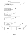
- FIG. 2 is a flow diagram of a process of decompressing bitstream data into digital images according to embodiments of the present invention.
- FIG. 3 illustrates groups 0 to 3 used for context prediction according to an embodiment of the present invention.
- Methods of compressing digital representations of images represent the images in multiple subsampling quality scales in a progressive manner that avoids accumulation of error.
- the methods are discussed with reference to still images.
- the present methods are also applicable to video images.
- the images treated by the present methods are primarily three-color images represented in terms of a primary color component (denoted by P) and secondary color components (denoted by S and Q,) associated with pixels forming a two-dimensional array.
- P primary color component
- S and Q secondary color components
- the methods can be extended to single-color or multi-color images, as well.
- the P, S, and Q components correspond, for example, to the G, R, and B components, respectively, in the RGB color space and to the Y, U, and V components, respectively in the YUV luminance/chrominance color space.
- the input to the data compression methods is a two-dimensional array of pixels each having three color components, and the output is a one-dimensional bitstream of compressed data.
- the methods can be implemented in software running on a general purpose computer processing unit (CPU) or a digital signal processor (DSP), in hardware, for example a VLSI chip, or in a combination of hardware and software.
- CPU general purpose computer processing unit
- DSP digital signal processor
- the computer instructions for carrying out the methods may be stored in a memory associated with the CPU or DSP.
- apparatus refers to a dedicated hardware apparatus with pre-programmed instructions, general purpose computer and associated memory with stored instructions, or any combination of dedicated hardware and computers executing instructions.
- a compressed image may be stored on a memory for later retrieval and display on a monitor or may be transmitted over an internal network or an external network such as the Internet.
- an original image is decomposed into multiple quality scales from a highest quality scale, which is termed the Compression Quality Scale (CQS) to a lowest, or base, quality scale, termed the Subsampling Quality Scale (SQS).
- CQS Compression Quality Scale
- SQS Subsampling Quality Scale
- the image data at the base quality scale, SQS is output first, followed by the next scale, and so forth until the data at the CQS is output.
- the differentiation stage, 120 represents the subsampled images in a differential form such that each differential image contains only data additional to the image at a lower quality scale.
- the differentiation stage which includes stages 125 to 170 , determines the difference between a subsampled image and a reference image scaled up from a reconstructed image subsampled at the adjacent lower quality scale.
- the reconstructed image is formed by treating a subsampled image by a lossy transformation, consisting here of a transform stage 130 and a quantize stage 140 and then reconstructing the image by a dequantize stage 150 , which is the inverse of stage 140 , and an inverse transform stage 160 .
- the output of the differentiation stage 120 is the quantized base quality scale and the quantized differential images.
- the quantized base image and differential images are converted to a bitstream of compressed data by a lossless ordered statistics encoding process.
- the ordered statistics encoding process includes a context prediction stage 185 , an ordering stage 190 , in which the two-dimensional array referenced to pixels is converted to a one-dimensional array, and a lossless entropy encoding stage 195 , such as arithmetic encoding.
- a decompression method essentially reverses the compression process as shown in FIG. 2 and discussed in detail below.
- a total of seven subsampling scales are defined for use at subsampling stage 110 , although different subsampling sequences can be defined similarly.
- the seven subsampling scales are enumerated from 0 to 6, with 0 representing the highest quality scale, and 6 the lowest quality scale. Each scale number indicates a particular way of subsampling the image data
- Mode 1 of the 4:2:2 subsampling method is the same as the subsampling scheme used in the TV industry and as the MPEG2 Standard for transmitting moving images.
- an “x” indicates a missing component.
- the S and Q components are diagonally aligned so that the spacing is uniform along horizontal and vertical directions for S and Q components.
- Mode 2 is a preferred subsampling mode for scale 1.
- the third mode is a trivial variation of Mode 2 with the positions of S and Q interchanged, as shown in Table 4.
- the fourth mode is a transposed mode of Mode 1, with spacing favoring the horizontal direction.
- the fifth and sixth modes are trivial variations of Mode 1 and 4, with the positions of S and Q interchanged.
- the first mode is similar to the YUV 4:2:0 chroma format used in MPEG2 and JPEG standards. In this mode, every four pixels of P share a pair of S and Q components, located at the center of the four P pixels. In the second mode, the S and Q components are not co-sited. Rather, they are aligned diagonally and co-sited with a different P pixel, as shown in Table 9.
- Scale 3 is the Bayer Pattern which is often used as a sampling pattern in imaging sensor technology. In scale 3 there are four modes, each defining a particular structure of color components. In the first mode, shown in Table 13, only one color component is preserved as each pixel location. The primary color has twice as many elements as the secondary colors.
- each pixel at scale 4 represents a larger area of the image.
- the color components are represented in the 4:4:4 pattern of scale 0.
- an original image I M ⁇ N of M ⁇ N pixels is first scaled down by a factor of L horizontally and vertically into an image I m ⁇ n of size m ⁇ n, where
- n ( N+L ⁇ 1)/ L.
- I m ⁇ n is represented in 4:4:4 format.
- L is selected as 2 or 3.
- an image I M ⁇ N of M ⁇ N pixels is scaled down by a factor of L horizontally and vertically into an image I m ⁇ n of size m ⁇ n, as described above and subsampled in 4:2:2 format.
- an image is scaled down by a factor of L horizontally and vertically and subsampled in 4:2:0 format.
- L for example, a value of either 2 or 3
- scales 4 to 6 all refer to the same number of pixels.
- the scaling-down and scaling-up algorithms are used in pairs, denoted by (Lx ⁇ ,Lx ⁇ ), where L is a scaling factor, and Lx defines the scaling algorithm.
- Lx is a scaling factor
- Lx defines the scaling algorithm.
- the optimal choice of particular scaling algorithm depends on the characteristics of the image data. By pairing, the same L is used for both scaling down (Lx ⁇ ) and scaling up (Lx ⁇ ). Scaling may be performed on some or all of the color components of an image, depending on the subsampling patterns and from which scale an image is subsampled.
- an original image I must be in one of the representations of Scales 0, 1, 2, and 3 described above.
- An image in the 4:2:2 pattern is obtained from an image in the 4:4:4 pattern with scaling down the UV or RB components by a factor of 2 along only the horizontal direction. This scaling down along the horizontal direction is performed by a 2x ⁇ algorithm.
- the vertical sizes of the YUV or RGB components are the same for a 4:4:4 pattern and a 4:2:2 pattern.
- an image in the 4:2:0 pattern is obtained from an image in the 4:2:2 pattern by scaling down the UV or RB components by a factor of 2 along only the vertical direction.
- a Bayer pattern is obtained from a 4:2:0 image with scaling down the P component image horizontally or vertically, but not both.
- I 2 is in 4:2:0 format.
- I G we use the decimation algorithm to reduce I 2 into one of the Bayer Patterns, I 3 , as shown in Tables 13-16.
- I 3 we use the given 2 ⁇ algorithm to scale down the P component of I 2 and reduce I 2 to I 4 , which is in 4:4:4 format at a lower dimension.
- I 4 can also be obtained from I 0 directly with scaling down all color components using a given 2 ⁇ algorithm.
- Sequence I For SQS values less than 3, either Sequence I or Sequence II can be used. For an SQS value of 3, Sequence II is used. For SQS values greater than 3, Sequence I is used. In Sequence II, the decimation method is preferred in the subsampling at Scales 1 and 2. In Sequence I, Scale 3 is skipped in order to avoid the non-cositedness problem. More sophisticated scaling methods can be used for Sequence I.
- a sequence of differential images may be defined differently for Sequences I and II.
- the subsampled sequence contains a subset of ⁇ I 0 , I 1 , I 2 , I 3 ⁇ .
- the differential image D S between I S and I S+1 may be defined as the extra pixels or components present in I S but not in I S+1 .
- D S may be written as
- the subsampled sequence contains a subset of ⁇ I 0 , I 1 , I 2 , I 4 , I 5 , I 6 ⁇ .
- we scale an image at lower scales up to a higher scale For example, we use the given 2 ⁇ algorithm to scale the P components of I 4 to obtain a higher scale image J 2 .
- we scale up the S and Q components of I k to obtain a higher scale image J k ⁇ 1 , for k 6, 5, 2, 1. Then the differential image at scale k is defined as
- the differential images produced at the differentiation stage 120 of FIG. 1 take a different form.
- the differential representation described above has the disadvantage of error propagation from the lowest quality scale to higher quality scales.
- the reference image used for subtraction needs to be replaced by an image reconstructed from the data of lower scales.
- Sequence II is simpler and can be similarly treated.
- SQS S and CQS C first obtain the subsampled sequence ⁇ I C , I C+1 , . . . , I S ⁇ .
- the base quality scale image I S is treated by a lossy transformation consisting of transform stage 130 and quantize stage 140 .
- the transform stage 130 can be performed using the DCT or wavelet transforms, as used, respectively, in standard JPEG or JPEG2000 methods. Alternatively, transform stage 130 can use a new discrete cosine wavelet transform defined below in the present application.
- G S Reconstructing I S , by applying the inverse of the lossy transformation, we can obtain G S .
- G S is different from I S , because lossy processes were used at stages 130 and 140 .
- H S ⁇ 1 Using the given Lx ⁇ algorithm, we scale up G S to a higher scale S ⁇ 1 and obtain H S ⁇ 1 . Then we obtain D S ⁇ 1 from
- D S ⁇ 1 is transformed and quantized.
- D′ S ⁇ 1 represent the transformed and quantized D S ⁇ 1 .
- D S ⁇ 2 I S ⁇ 2 ⁇ H S ⁇ 2 .
- D S ⁇ 2 is transformed and quantized to give D′ S ⁇ 2 and from D′ S ⁇ 2 we can obtain G S ⁇ 2 .
- This process goes on until the differential image D C at the highest quality scale C is determined, transformed, and quantized.
- the quantity H k differs from J k defined above in that H k is reconstructed from lower scale image data transformed and quantized using lossy methods, while J k is an image scaled up from a lower quality scale image I k+1 .
- Subtract stage 125 computes the difference between a subsampled image and the reconstructed upscaled image as given explicitly for scale S ⁇ 1 in Eq. (1).
- the output D′ of quantize stage 140 is passed to both the ordered statistics encoding stage 180 and to the dequantize stage 150 to complete the process of determining the differentials.
- the output of the inverse transform stage 160 is the quantity denoted by G, that is the reconstructed D′.
- the add stage 165 adds the reconstructed differential G to the image scaled up from the adjacent lower scale H, as given explicitly for scale S ⁇ 1 in Eq. (2).
- the flow diagram describes the overall differentiation process, producing a sequence of transformed and quantized images ⁇ D′ S , D′ S ⁇ 1 , . . . D′ C ⁇
- the transform stage 130 may refer to standard transformations into coefficients associated with known functions such as the discrete cosine transform (DCT), wavelet transforms (WT), or other similar transforms known in the art.
- DCT discrete cosine transform
- WT wavelet transforms
- DWCT discrete wavelet cosine transform
- the DWCT transform combines spatial transformation features of the Haar (wavelet) transform and frequency transformation features of the DCT.
- a bold face letter such as X or Y is used to represent a vector.
- a subscript is used to denote the dimension of the vector.
- X N represents a vector of N elements, whose nth element is represented by X N [n].
- Round brackets (and) are used to enclose the variables of a function (e.g. f(x)), while square brackets [and] and are used to enclose an index of a vector element (e.g., X[n]).
- Interleave( X N , Y N ) [ x 0 , y 0 , x 1 , y 1 , . . . , x N ⁇ 1 , y N ⁇ 1 ] T .
- a permutation function T N (X N ) for size N is defined as
- T N (X N ) is inversible and can be expressed in matrix form
- the DWCT is defined recursively. To clarify the relationship between the DWCT and the previously used DCT and wavelet transforms, first a recursive definition of the DCT is provided.
- the DCT at size N can be recursively defined in terms of DCTs at size N/2 through
- Q N/ 2 is a vector of only N/2 elements.
- E N/2 [n], Q N/2 [n], and therefore C N are defined by DCTs at a lower dimension N/2 instead of N.
- H N defines the one-dimensional HT of size N.
- the HT at size N can be recursively defined in terms of HTs at size N/2 through
- the one-dimensional DWCT is also defined recursively.
- the DWCT W 2 (X 2 ) at size 2 is defined to be the same as the DCT or HT:
- W N (X N ) looks somewhat equivalent to the composite function C N (T N (X N )), they are not the same. T N (X N ) permutes only X N at size N, while W N (X N ) permutes the data at each recursion.
- the DWCT may be thought of as a variant of the DCT in the sense DWCT is defined using the DCT and a permutation function. Permutation does not change the value of the input, but only the order of the input.
- the even part, E N/2 , of DWCT is the same as the even part of the Haar Transform. Therefore DWCT differs from HT only in the odd part, which corresponds to high frequencies.
- the elements of the vector Y N are referred to as the DWCT coefficients.
- DWCT coefficients can be derived from HT coefficients with some additional computations on the odd part and vice versa.
- DWCT is also a multi-resolution representation of the data with the even part of the data containing the lower scales of representations of the input. In a general sense, the DWCT is also a wavelet transform because at each recursion DWCT can be considered a scaled Haar transform.
- the end result is a compact representation in which the lowest order coefficients have the most information about the image.
- the DWCT is defined here in the context of the present data compression process in which differential images are defined from reconstructed representations, the DWCT may be applied in any data compression method.
- alternate data compression methods could be defined in which DWCT replaces the DCT or wavelet transforms of JPEG or JPEG2000, respectively.
- the recursive definition, Eqs, (3)-(10) can be evaluated each time the DWCT transform is calculated.
- the transformation matrices W N can be determined explicitly as a function of N, from the original X N and Eq. (4), and stored.
- the recursive definition has the advantage of being applicable to any value of N.
- a recursive definition of the inverse of the DWCT, which may be denoted IDWCT, may be derived mathematically from Eqs. (3)-(10) since all the equations are linear.
- the inverse transformation may be calculated explicitly from the forward transformation and stored.
- the transform is applied to the rows of the two-dimensional array, treating each row as a one-dimensional vector, and then the transform is applied to the columns of the array, again treating each column as a one-dimensional vector.
- the DWCT is applied to each color component separately. That is, each color component is extracted as a monochromatic component image and then the DWCT is applied to each of the component images.
- a low-frequency extension method is applied.
- These added elements can have any values because they will be discarded by the decoder.
- the present low frequency extension is to choose the values of x L , x L+1 , . . . , x N ⁇ 1 to make the DWCT transform of X N have only up to L non-zero coefficients.
- X L w L ⁇ L Z L
- Z L w L ⁇ L ⁇ 1 X L
- X (N ⁇ L) in the above equation provides a low-frequency extension to the original data X L .
- the two-dimensional case is treated by considering the column vectors first and then row vectors of the transformed image (by transposing the image).
- the same principle can be applied to any other transform such as the DCT, Fourier Transform, or wavelet transform.
- the original image may be divided into blocks and DWCT can be performed on each block instead of the whole image.
- DWCT can be performed on each block instead of the whole image.
- Block size can be as big as the whole image for best quality. However, computational resource requirement increases significantly when block sizes increase.
- the process of dividing an image into blocks is equally applicable to alternative transforms used at stage 130 . Referring to the flow diagram of FIG. 1, the image may be divided into blocks immediately before the transform stage 130 such that the transform process 130 and quantize process 140 are then performed in terms of blocks. In completing the loop within the differentiation stage 120 , a blocked image is deblocked immediately after the inverse transform at stage 160 .
- a block of coefficients is quantized to fixed-point data by dividing each coefficient with a quantizer and rounding the result to the nearest integer.
- the quantizers can be freely chosen according to application needs.
- the DWCT, or other transform, of an M ⁇ M block image yields a block of M ⁇ M coefficients.
- block may refer to the entire image.
- the collection of quantizers for the coefficients in a block forms a quantizer block, called a quantization table.
- a fixed number of quantizer tables are used in a given image such that a different coefficient block may use a different quantization table.
- Table 17 The structure of a quantizer block is shown in Table 17.
- C(x,y) be, for example, the DWCT coefficients of an image block and Q(x,y) be the selected quantizer block.
- the quantization process is described by the following equation:
- dequantize stage 150 uses an inverse quantization table.
- the quantized coefficients for each block are encoded in a lossless manner executed in three stages: context prediction 185 , ordering 190 , and entropy encoding 195 .
- an improved method of context prediction uses a context that is different for each color component and for each coefficient.
- the context consists of neighboring pixels in the same block.
- the context consists of neighboring coefficients in the same block and the coefficient of the same index in the corresponding primary color block.
- the context consists of neighboring coefficients in the same block and the coefficients of the same index in the corresponding primary and second color blocks.
- Coefficients of index 0 are predicted differently, utilizing the coefficients of index 0 in the neighboring blocks in addition to the same coefficients in the primary or second color components.
- a context of any order can be used; however, typically, orders 2 and 3 are used.
- An order 3 context is formed by three coefficients C 1 , C 2 , and C 3 from the same or different blocks.
- An order 2 context contains C 1 and C 2 only. The context described below is for order 3.
- the order 2 context is obtained by discarding one coefficient, usually the least relevant one, in the context.
- the coefficients in a block are classified into 4 groups.
- the context for each group is formed using different rules:
- Group 0 contains the coefficient at location (0,0) only.
- Group 1 contains the coefficients on the first row except coefficient (0,0). This group of coefficients has an index represented by (0,i), with i>0.
- Group 2 contains the coefficients on the first column except coefficient (0,0). This group of coefficients has an index represented by (j,0), with j>0.
- Group 3 contains all the rest of the coefficients. This group of coefficients have an index represented by (i,j), with i>0, j>0.
- the context is formed by C 1 only.
- the context of a coefficient P j,0 in Group 2 is formed by the 3 coefficients on the same column preceding P j,0 . If C 3 or C 2 is out of the block, then the context is formed by C 1 only.
- the context of a coefficient P j,i in Group 3 is formed by the 3 neighboring coefficients on the upper left side of P j,i :
- coefficient (0,0) The context for coefficient (0,0) is formed differently. First, all coefficients (0,0) from different blocks of the primary color are grouped together to form an index image. The index image is treated like a regular primary component block and DWCT is applied to the index image to obtain a coefficient block. The Groups 1, 2, and 3 are predicted using the context described above. The coefficient at position (0,0) is predicted using a constant 2 H ⁇ 1 for an image of H-bits precision.
- the context for coefficient (0,0) of the second color component S is formed analogously to the context for coefficient (0,0) of the primary color component.
- All coefficients (0,0) from different blocks of the second color are grouped together to form an index image.
- This index image is treated like a regular second component block and DWCT is applied to this index image to obtain a coefficient block.
- the Groups 1, 2, and 3 are predicted using the context described above for the second component.
- Coefficient 0 is predicted using a constant 2 H ⁇ 1 for an image of H-bits precision.
- coefficient (0,0) of the third color component is formed analogously to the process described above for the (0,0) coefficients of the primary and second color components.
- the positional index of each coefficient in a DWCT block can also be used as a context.
- the positional context is denoted by C 0 .
- the context prediction method described here may be applied in any data compression method.
- the present context prediction method may be used in conjunction with entropy encoding steps in a JPEG- or JPEG2000-like method.
- the pixel context and positional context together form the whole context for probability modeling.
- the whole context is denoted by C 3 C 2 C 1 C 0 .
- X) is used subsequently at stage 195 to encode the coefficient X.
- the maximum order of the context may be reduced from 4 to 3 or 2 for computational reasons in practical applications.
- the two-dimensional array of pixels is mapped into a one-dimensional sequence for the purpose of efficient encoding.
- ordering follows context prediction.
- ordering can be done before quantization or context prediction as long as the mapping is preserved for all relevant data such as coefficients, quantization tables, and contexts.
- Conventional methods of ordering include the zig-zag ordering scheme used in JPEG.
- quad-tree ordering is defined here.
- the quad-tree ordering method is particularly suited to take advantage of the data compaction of the DWCT transform which places the most important coefficients at the upper left corner of the two-dimensional array.
- each block is partitioned into four priority regions (PRs) of equal sizes as shown in Table 18.
- PRs priority regions
- Priority 0 is the region of highest priority and Priority 3 is the region of lowest priority. In the bitstream, regions of Priority 0 appears ahead of regions of Priority 1, followed by regions of Priority 2 and then 3.
- Each region is further partitioned into sub priority regions using the same method as shown above. This process continues until the region size reaches 1 pixel by 1 pixel.
- Table 19 shows the ordering result for a block of size 16 ⁇ 16. The same method can be applied to any sized block.
- the output of the ordering method includes a table relating the two index pixel position to the coefficient order in the one-dimensional array as illustrated above.
- the final stage of the data compression method is entropy encoding 195 .
- the ordered, quantized coefficients are entropy encoded based on the conditional probability based on the context determined in stage 185 .
- Any lossless encoding method may be used but arithmetic encoding is preferred. Standard methods of arithmetic encoding are described, for example, in the reference book by Mark Nelson and Jean-Loup Gailly, The Data Compression Book (M&T Books, 1995).
- X) where X is the coefficient to be encoded, is initialized from a constant table obtained a priori and then updated using accumulated statistics for the image of interest.
- C 0 is the positional index in the one-dimensional array resulting from the ordering stage. If X is not in the prediction table of C 3 C 2 C 1 C 0 , the prediction order is reduced to 3 and the prediction table of C 2 C 1 C 0 is examined. If X is in the prediction table of C 2 C 1 C 0 , then P(C 2 C 1 C 0
- X) is used to encode X. Otherwise, the order is reduced to 2 and the prediction table of C 1 C 0 is examined. The process continues until order 1 is reached.
- X is encoded assuming a uniform probability for the values not in the prediction tables of C 3 C 2 C 1 C 0 , C 2 C 1 C 0 , C 1 C 0 , and C 0 .
- a value to be encoded is called a symbol.
- the prediction tables for different orders are disjoint, as they contain no common symbols. For example, if X is not in the prediction table of C 3 C 2 C 1 C 0 , then when we reduce the order from 4 to 3, all symbols in C 3 C 2 C 1 C 0 should be removed from the prediction table of C 2 C 1 C 0 when computing its symbol probabilities. Similarly, when we reduce the order from 3 to 2 (because X is not in the prediction table of C 2 C 1 C 0 ), all symbols in C 3 C 2 C 1 C 0 and C 2 C 1 C 0 should be removed from the prediction table of C 1 C 0 when computing its symbol probabilities.
- each conditional probability is represented by an occurrence count in fixed-point number format. The occurrence count is updated each time a value is encoded.
- the encoding stage completes the process of producing a bitstream that can be efficiently stored or transmitted over a computer network.
- the bitstream contains the encoded coefficients corresponding to the base quality scale image followed by the encoded coefficients corresponding to the differential images.
- the bitstream may contain conventional header information such as the size of the file, number of colors, number of scales, information about how the file is ordered, such as a block sequential index, identification of methods used, for example to transform and encode, non-default quantization tables, and optionally, probability tables.
- a decompression process essentially reverses the operation at each step of the process and thus enables the image to be reconstructed.
- the decompression process needs to have access to the probability tables used for entropy encoding.
- the probability tables may be stored as part of the header information, they are generally large. Therefore, at stage 210 , the probability prediction tables are typically generated by an analogous context prediction process as that used at stage 185 . However, the context prediction process used information about neighboring pixels.
- the portion of the decompression process indicated by loop 280 which reverses the ordered statistics encoding, is performed as a loop over pixel positions to gradually build up the probability tables.
- the bitstream data is restored to the quantized transform coefficients.
- the reverse order stage 230 maps the one-dimensional coefficient data back into the two-dimensional position.
- the dequantize stage 250 reverses the quantization process using an inverse quantization table.
- the inverse transform stage 260 transforms the dequantized coefficients back into the pixel data. Note that stages 250 and 260 use precisely the same processes as stages 150 and 160 , used in the loop within the differentiation stage 120 .
- the output of the inverse transform stage 260 may be the sequence of differential images starting with the base quality scale image G S denoted as ⁇ G S , G S ⁇ 1 , . . . G C ⁇ where the G's are not exactly the same as the original images I S etc. since they have undergone lossy transformations.
- G S is scaled up to yield a higher scale image H S ⁇ 1 .
- the image F S ⁇ 2 is scaled up to the next image scale to give H S ⁇ 1 and the process is continued until the digital representation of the highest quality scale image is recovered.
- H S 0
- the recombination process 290 is described in the flow diagram in FIG. 2 where the add stage 265 adds the reconstructed differential G to the image scaled up from the adjacent lower scale H as in Eq. (2).
- DQS Display Quality Scale
- the scale specified by an application is of lower quality than the quality at which the image was stored, only the differentials corresponding to the DQS scale need to be recovered.
- the flow of the processes in FIG. 2 can be altered so that the differentials G are obtained one at a time, from stages 210 through 260 , and added to the previous upscaled image before the differential at the next quality scale is inverse transformed. In this way all the information needed to display an image at a given quality scale may be determined before any information required for the next higher quality scale is computed.
- an image compressed according to the present process can be progressively viewed or downloaded by transmission over a computer network or the Internet. Further, a browser can display an image at a specified quality scale, ignoring any data corresponding to quality scales higher than the specified scale.
Landscapes
- Engineering & Computer Science (AREA)
- Multimedia (AREA)
- Physics & Mathematics (AREA)
- General Physics & Mathematics (AREA)
- Theoretical Computer Science (AREA)
- Compression Or Coding Systems Of Tv Signals (AREA)
- Compression Of Band Width Or Redundancy In Fax (AREA)
- Color Television Systems (AREA)
- Compression, Expansion, Code Conversion, And Decoders (AREA)
Priority Applications (8)
| Application Number | Priority Date | Filing Date | Title |
|---|---|---|---|
| US09/792,668 US6757429B2 (en) | 2001-02-21 | 2001-02-21 | Method of compressing digital images |
| US09/860,109 US6823082B2 (en) | 2001-02-21 | 2001-05-16 | Method of compressing digital images |
| EP20020251038 EP1235185B1 (de) | 2001-02-21 | 2002-02-15 | Verfahren zur Kompression digitaler Bilder |
| AT02251038T ATE534976T1 (de) | 2001-02-21 | 2002-02-15 | Verfahren zur kompression digitaler bilder |
| CA 2372514 CA2372514C (en) | 2001-02-21 | 2002-02-18 | Method of compressing digital images |
| CA2676099A CA2676099C (en) | 2001-02-21 | 2002-02-18 | Method of compressing digital images |
| CN02104793.6A CN1222153C (zh) | 2001-02-21 | 2002-02-20 | 数字图象压缩方法 |
| JP2002045193A JP4116304B2 (ja) | 2001-02-21 | 2002-02-21 | デジタル画像の圧縮方法 |
Applications Claiming Priority (1)
| Application Number | Priority Date | Filing Date | Title |
|---|---|---|---|
| US09/792,668 US6757429B2 (en) | 2001-02-21 | 2001-02-21 | Method of compressing digital images |
Related Child Applications (1)
| Application Number | Title | Priority Date | Filing Date |
|---|---|---|---|
| US09/860,109 Continuation-In-Part US6823082B2 (en) | 2001-02-21 | 2001-05-16 | Method of compressing digital images |
Publications (2)
| Publication Number | Publication Date |
|---|---|
| US20030053702A1 US20030053702A1 (en) | 2003-03-20 |
| US6757429B2 true US6757429B2 (en) | 2004-06-29 |
Family
ID=25157665
Family Applications (2)
| Application Number | Title | Priority Date | Filing Date |
|---|---|---|---|
| US09/792,668 Expired - Lifetime US6757429B2 (en) | 2001-02-21 | 2001-02-21 | Method of compressing digital images |
| US09/860,109 Expired - Fee Related US6823082B2 (en) | 2001-02-21 | 2001-05-16 | Method of compressing digital images |
Family Applications After (1)
| Application Number | Title | Priority Date | Filing Date |
|---|---|---|---|
| US09/860,109 Expired - Fee Related US6823082B2 (en) | 2001-02-21 | 2001-05-16 | Method of compressing digital images |
Country Status (5)
| Country | Link |
|---|---|
| US (2) | US6757429B2 (de) |
| JP (1) | JP4116304B2 (de) |
| CN (1) | CN1222153C (de) |
| AT (1) | ATE534976T1 (de) |
| CA (1) | CA2676099C (de) |
Cited By (17)
| Publication number | Priority date | Publication date | Assignee | Title |
|---|---|---|---|---|
| US20020172418A1 (en) * | 2001-02-21 | 2002-11-21 | Xiaoping Hu | Method of compressing digital images |
| US20020171855A1 (en) * | 2001-03-30 | 2002-11-21 | Edge Christopher J. | Automated sharpening of images for soft proofing |
| US20040156552A1 (en) * | 2003-02-03 | 2004-08-12 | Actimagine | Process and device for the compression of portions of images |
| US20050062755A1 (en) * | 2003-09-18 | 2005-03-24 | Phil Van Dyke | YUV display buffer |
| US20050285813A1 (en) * | 2004-06-23 | 2005-12-29 | Atsushi Obinata | Display controller, electronic equipment, and image data supplying method |
| US7069342B1 (en) * | 2001-03-01 | 2006-06-27 | Cisco Technology, Inc. | Communication system with content-based data compression |
| US20080091845A1 (en) * | 2006-10-13 | 2008-04-17 | Mills Brendon W | System and method for processing content |
| US20080304761A1 (en) * | 2003-02-03 | 2008-12-11 | Actimagine | Process and device for the compression of portions of images |
| US20100070608A1 (en) * | 2008-09-10 | 2010-03-18 | Ripcode, Inc. | System and method for delivering content |
| US20100094931A1 (en) * | 2008-10-14 | 2010-04-15 | Ripcode, Inc. | System and method for progressive delivery of media content |
| US20100128039A1 (en) * | 2008-11-26 | 2010-05-27 | Kwang-Jun Cho | Image data processing method, image sensor, and integrated circuit |
| US8055069B2 (en) | 2005-02-05 | 2011-11-08 | Via Technologies, Inc. | Image data sampling method |
| US8627509B2 (en) | 2007-07-02 | 2014-01-07 | Rgb Networks, Inc. | System and method for monitoring content |
| US8811756B2 (en) | 2011-07-11 | 2014-08-19 | International Business Machines Corporation | Image compression |
| US9282131B2 (en) | 2009-01-20 | 2016-03-08 | Imagine Communications Corp. | System and method for splicing media files |
| US9294728B2 (en) | 2006-01-10 | 2016-03-22 | Imagine Communications Corp. | System and method for routing content |
| US10291918B2 (en) | 2015-09-02 | 2019-05-14 | Kabushiki Kaisha Toshiba | Image compression apparatus, image expansion apparatus, and image transfer system |
Families Citing this family (61)
| Publication number | Priority date | Publication date | Assignee | Title |
|---|---|---|---|---|
| JP3349957B2 (ja) * | 1997-07-09 | 2002-11-25 | 株式会社ハイニックスセミコンダクター | コンテキスト確率表を利用した二進映像情報の内挿装置および方法 |
| US7136418B2 (en) * | 2001-05-03 | 2006-11-14 | University Of Washington | Scalable and perceptually ranked signal coding and decoding |
| US6944639B2 (en) * | 2001-06-29 | 2005-09-13 | Nokia Corporation | Hardware context vector generator for JPEG2000 block-coding |
| JP4267848B2 (ja) * | 2001-09-25 | 2009-05-27 | 株式会社リコー | 画像符号化装置、画像復号装置、画像符号化方法、及び、画像復号方法 |
| KR101030862B1 (ko) * | 2001-11-22 | 2011-04-22 | 파나소닉 주식회사 | 부호화 방법 및 부호화 장치 |
| US7129962B1 (en) * | 2002-03-25 | 2006-10-31 | Matrox Graphics Inc. | Efficient video processing method and system |
| JP3959039B2 (ja) * | 2003-02-28 | 2007-08-15 | 株式会社エヌ・ティ・ティ・ドコモ | 画像符号化装置、画像符号化方法、画像符号化プログラム、画像復号装置、画像復号方法、及び画像復号プログラム |
| EP1453004A2 (de) * | 2003-02-28 | 2004-09-01 | NTT DoCoMo, Inc. | Bildcodierungsvorrichtung und -verfahren |
| US7200278B2 (en) * | 2003-03-14 | 2007-04-03 | Huaya Microelectronics, Ltd | 4×4 pixel-based edge detection and edge enhancement without line buffer overhead |
| TWI235003B (en) * | 2003-06-17 | 2005-06-21 | Inst Information Industry | Digital video encryption and decryption system and method thereof |
| WO2004114674A1 (ja) * | 2003-06-19 | 2004-12-29 | Matsushita Electric Industrial Co., Ltd. | 送信装置、画像処理システム、画像処理方法、プログラム、及び記録媒体 |
| FR2857527B1 (fr) * | 2003-07-11 | 2006-01-06 | Cit Alcatel | Compression contextuelle d'images numeriques |
| US20050128192A1 (en) * | 2003-12-12 | 2005-06-16 | International Business Machines Corporation | Modifying visual presentations based on environmental context and user preferences |
| US7801383B2 (en) * | 2004-05-15 | 2010-09-21 | Microsoft Corporation | Embedded scalar quantizers with arbitrary dead-zone ratios |
| US20060008154A1 (en) * | 2004-07-01 | 2006-01-12 | Belle Ronny V | Video compression and decompression to virtually quadruple image resolution |
| US7565020B2 (en) * | 2004-07-03 | 2009-07-21 | Microsoft Corp. | System and method for image coding employing a hybrid directional prediction and wavelet lifting |
| JP2006191485A (ja) * | 2005-01-07 | 2006-07-20 | Ntt Docomo Inc | 画像信号変換方法、画像符号化装置、画像符号化方法、画像符号化プログラム、画像復号装置、画像復号方法及び画像復号プログラム |
| US8073275B2 (en) * | 2005-02-09 | 2011-12-06 | Mobixell Networks Ltd. | Image adaptation with target size, quality and resolution constraints |
| US7583844B2 (en) * | 2005-03-11 | 2009-09-01 | Nokia Corporation | Method, device, and system for processing of still images in the compressed domain |
| US8422546B2 (en) | 2005-05-25 | 2013-04-16 | Microsoft Corporation | Adaptive video encoding using a perceptual model |
| US7552386B2 (en) * | 2005-06-10 | 2009-06-23 | Microsoft Corporation | Methods and systems for treating overflow conditions and for re-sizing printable content |
| CA2610276C (en) * | 2005-07-22 | 2013-01-29 | Mitsubishi Electric Corporation | Image encoder and image decoder, image encoding method and image decoding method, image encoding program and image decoding program, and computer readable recording medium recorded with image encoding program and computer readable recording medium recorded with image decoding program |
| JP4769039B2 (ja) * | 2005-07-26 | 2011-09-07 | パナソニック株式会社 | デジタル信号符号化および復号化装置ならびにその方法 |
| US7974340B2 (en) * | 2006-04-07 | 2011-07-05 | Microsoft Corporation | Adaptive B-picture quantization control |
| US8059721B2 (en) * | 2006-04-07 | 2011-11-15 | Microsoft Corporation | Estimating sample-domain distortion in the transform domain with rounding compensation |
| US7995649B2 (en) | 2006-04-07 | 2011-08-09 | Microsoft Corporation | Quantization adjustment based on texture level |
| US8503536B2 (en) * | 2006-04-07 | 2013-08-06 | Microsoft Corporation | Quantization adjustments for DC shift artifacts |
| US8130828B2 (en) * | 2006-04-07 | 2012-03-06 | Microsoft Corporation | Adjusting quantization to preserve non-zero AC coefficients |
| US8711925B2 (en) * | 2006-05-05 | 2014-04-29 | Microsoft Corporation | Flexible quantization |
| CN100409693C (zh) * | 2006-07-13 | 2008-08-06 | 王国秋 | 用于图像和视频压缩的正交变换方法 |
| US9247259B2 (en) * | 2006-10-10 | 2016-01-26 | Flash Networks Ltd. | Control of video compression based on file size constraint |
| CN100548699C (zh) * | 2006-10-16 | 2009-10-14 | 光宝科技股份有限公司 | 热打印装置及其打印方法 |
| US8238424B2 (en) * | 2007-02-09 | 2012-08-07 | Microsoft Corporation | Complexity-based adaptive preprocessing for multiple-pass video compression |
| US8498335B2 (en) * | 2007-03-26 | 2013-07-30 | Microsoft Corporation | Adaptive deadzone size adjustment in quantization |
| US7983505B2 (en) * | 2007-03-30 | 2011-07-19 | Intel Corporation | Performing deblocking on pixel data |
| US8243797B2 (en) | 2007-03-30 | 2012-08-14 | Microsoft Corporation | Regions of interest for quality adjustments |
| US8442337B2 (en) * | 2007-04-18 | 2013-05-14 | Microsoft Corporation | Encoding adjustments for animation content |
| US8260068B2 (en) * | 2007-05-17 | 2012-09-04 | Sony Corporation | Encoding and decoding device and associated methodology for obtaining a decoded image with low delay |
| US8331438B2 (en) * | 2007-06-05 | 2012-12-11 | Microsoft Corporation | Adaptive selection of picture-level quantization parameters for predicted video pictures |
| US8189933B2 (en) * | 2008-03-31 | 2012-05-29 | Microsoft Corporation | Classifying and controlling encoding quality for textured, dark smooth and smooth video content |
| US8897359B2 (en) * | 2008-06-03 | 2014-11-25 | Microsoft Corporation | Adaptive quantization for enhancement layer video coding |
| US20100312828A1 (en) * | 2009-06-03 | 2010-12-09 | Mobixell Networks Ltd. | Server-controlled download of streaming media files |
| EP2362658A1 (de) * | 2010-02-26 | 2011-08-31 | Research In Motion Limited | Codierungs- und Decodierungsverfahren und Vorrichtungen mit Doppelcodesätzen |
| US7990297B1 (en) | 2010-02-26 | 2011-08-02 | Research In Motion Limited | Encoding and decoding methods and devices employing dual codesets |
| US8527649B2 (en) * | 2010-03-09 | 2013-09-03 | Mobixell Networks Ltd. | Multi-stream bit rate adaptation |
| ES2912048T3 (es) * | 2010-04-13 | 2022-05-24 | Ge Video Compression Llc | Codificación de mapas de significado y bloques de coeficiente de transformada |
| US8761240B2 (en) | 2010-07-13 | 2014-06-24 | Blackberry Limited | Methods and devices for data compression using context-based coding order |
| US8832709B2 (en) | 2010-07-19 | 2014-09-09 | Flash Networks Ltd. | Network optimization |
| CA2798125C (en) | 2010-07-28 | 2016-04-05 | Research In Motion Limited | Method and device for compression of binary sequences by grouping multiple symbols |
| CN103238334A (zh) | 2010-10-01 | 2013-08-07 | 三星电子株式会社 | 图像帧内预测方法和设备 |
| US8688074B2 (en) | 2011-02-28 | 2014-04-01 | Moisixell Networks Ltd. | Service classification of web traffic |
| CN103313046B (zh) * | 2012-03-06 | 2019-06-14 | 中兴通讯股份有限公司 | 一种残差的表示方法和熵编码输入装置 |
| CN102868847B (zh) * | 2012-10-19 | 2014-12-10 | 北京奇虎科技有限公司 | 基于图片类型的处理方法及设备 |
| US9648350B2 (en) * | 2013-07-22 | 2017-05-09 | Texas Instruments Incorporated | Method and apparatus for decoding a progressive JPEG image |
| US20160234520A1 (en) * | 2013-09-16 | 2016-08-11 | Entropic Communications, Llc | Efficient progressive jpeg decode method |
| US9936213B2 (en) * | 2013-09-19 | 2018-04-03 | Entropic Communications, Llc | Parallel decode of a progressive JPEG bitstream |
| JP6463900B2 (ja) * | 2014-04-17 | 2019-02-06 | キヤノン株式会社 | 画像符号化装置及びその制御方法 |
| US9544608B1 (en) | 2015-07-03 | 2017-01-10 | Microsoft Technology Licensing, Llc | Lossless image compression for few-colored images |
| US10462495B2 (en) * | 2017-08-09 | 2019-10-29 | Vital Images, Inc. | Progressive lossless compression of image data |
| US10262451B1 (en) * | 2018-04-09 | 2019-04-16 | 8i Limited | View-dependent color compression |
| CN117111637B (zh) * | 2023-09-26 | 2024-05-10 | 江苏星湖科技有限公司 | 一种电力高空感知设备汇聚融合终端巡检控制方法及装置 |
Citations (5)
| Publication number | Priority date | Publication date | Assignee | Title |
|---|---|---|---|---|
| US5408542A (en) * | 1992-05-12 | 1995-04-18 | Apple Computer, Inc. | Method and apparatus for real-time lossless compression and decompression of image data |
| US5432870A (en) * | 1993-06-30 | 1995-07-11 | Ricoh Corporation | Method and apparatus for compressing and decompressing images of documents |
| US5973803A (en) * | 1995-03-16 | 1999-10-26 | Lexmark International, Inc. | Combined color halftoning |
| US6307971B1 (en) * | 1998-10-01 | 2001-10-23 | Sharewave, Inc. | Method and apparatus for digital data compression |
| US6594387B1 (en) * | 1999-04-30 | 2003-07-15 | Texas Instruments Incorporated | Enhanced color correction |
Family Cites Families (3)
| Publication number | Priority date | Publication date | Assignee | Title |
|---|---|---|---|---|
| US6545710B1 (en) * | 1995-08-11 | 2003-04-08 | Minolta Co., Ltd. | Image pick-up apparatus |
| US6031940A (en) * | 1996-11-27 | 2000-02-29 | Teralogic, Inc. | System and method for efficiently encoding video frame sequences |
| US6757429B2 (en) * | 2001-02-21 | 2004-06-29 | Boly Media Communications Inc. | Method of compressing digital images |
-
2001
- 2001-02-21 US US09/792,668 patent/US6757429B2/en not_active Expired - Lifetime
- 2001-05-16 US US09/860,109 patent/US6823082B2/en not_active Expired - Fee Related
-
2002
- 2002-02-15 AT AT02251038T patent/ATE534976T1/de active
- 2002-02-18 CA CA2676099A patent/CA2676099C/en not_active Expired - Fee Related
- 2002-02-20 CN CN02104793.6A patent/CN1222153C/zh not_active Expired - Fee Related
- 2002-02-21 JP JP2002045193A patent/JP4116304B2/ja not_active Expired - Fee Related
Patent Citations (5)
| Publication number | Priority date | Publication date | Assignee | Title |
|---|---|---|---|---|
| US5408542A (en) * | 1992-05-12 | 1995-04-18 | Apple Computer, Inc. | Method and apparatus for real-time lossless compression and decompression of image data |
| US5432870A (en) * | 1993-06-30 | 1995-07-11 | Ricoh Corporation | Method and apparatus for compressing and decompressing images of documents |
| US5973803A (en) * | 1995-03-16 | 1999-10-26 | Lexmark International, Inc. | Combined color halftoning |
| US6307971B1 (en) * | 1998-10-01 | 2001-10-23 | Sharewave, Inc. | Method and apparatus for digital data compression |
| US6594387B1 (en) * | 1999-04-30 | 2003-07-15 | Texas Instruments Incorporated | Enhanced color correction |
Non-Patent Citations (6)
| Title |
|---|
| Http://www.faqs.org/faqs/compression-faq/part2/section-3.html, [72] What is wavelet theory?, 3 pages, Jan. 9, 2001. |
| Http://www.faqs.org/faqs/compression-faq/part2/section-6.html, [75] Introduction to JPEG, 5 pages, Jan. 9, 2001. |
| Http://www.faqs.org/faqs/jpeg-faq/part1/section-1.html, [1] What is JPEG?, 2 pages, Jan. 8, 2001. |
| Http://www.faqs.org/faqs/jpeg-faq/part1/section-2.html, [2] Why use JPEG?, 2 pages, Jan. 8, 2001. |
| Http:/www.faqs.org/faqs/compression-faq/part2/section-1.html, [70] Introduction to data compression (long), 6 pages, Jan. 9, 2001. |
| Information Technology: JPEG 2000 Image Coding System, JPEG 2000 Committee Draft Version 1.0, pp. i-164, Dec. 9, 1999. |
Cited By (24)
| Publication number | Priority date | Publication date | Assignee | Title |
|---|---|---|---|---|
| US20020172418A1 (en) * | 2001-02-21 | 2002-11-21 | Xiaoping Hu | Method of compressing digital images |
| US6823082B2 (en) * | 2001-02-21 | 2004-11-23 | Boly Media Communications, Inc. | Method of compressing digital images |
| US7069342B1 (en) * | 2001-03-01 | 2006-06-27 | Cisco Technology, Inc. | Communication system with content-based data compression |
| US20020171855A1 (en) * | 2001-03-30 | 2002-11-21 | Edge Christopher J. | Automated sharpening of images for soft proofing |
| US20040156552A1 (en) * | 2003-02-03 | 2004-08-12 | Actimagine | Process and device for the compression of portions of images |
| US8131095B2 (en) | 2003-02-03 | 2012-03-06 | Actimagine | Process and device for the compression of portions of images |
| US20080304761A1 (en) * | 2003-02-03 | 2008-12-11 | Actimagine | Process and device for the compression of portions of images |
| US20050062755A1 (en) * | 2003-09-18 | 2005-03-24 | Phil Van Dyke | YUV display buffer |
| US20050285813A1 (en) * | 2004-06-23 | 2005-12-29 | Atsushi Obinata | Display controller, electronic equipment, and image data supplying method |
| US8055069B2 (en) | 2005-02-05 | 2011-11-08 | Via Technologies, Inc. | Image data sampling method |
| US9294728B2 (en) | 2006-01-10 | 2016-03-22 | Imagine Communications Corp. | System and method for routing content |
| US20080091845A1 (en) * | 2006-10-13 | 2008-04-17 | Mills Brendon W | System and method for processing content |
| US8180920B2 (en) | 2006-10-13 | 2012-05-15 | Rgb Networks, Inc. | System and method for processing content |
| US8627509B2 (en) | 2007-07-02 | 2014-01-07 | Rgb Networks, Inc. | System and method for monitoring content |
| US20100070608A1 (en) * | 2008-09-10 | 2010-03-18 | Ripcode, Inc. | System and method for delivering content |
| US9473812B2 (en) | 2008-09-10 | 2016-10-18 | Imagine Communications Corp. | System and method for delivering content |
| US10511646B2 (en) | 2008-09-10 | 2019-12-17 | Imagine Communications Corp. | System and method for delivering content |
| US20100094931A1 (en) * | 2008-10-14 | 2010-04-15 | Ripcode, Inc. | System and method for progressive delivery of media content |
| US9247276B2 (en) | 2008-10-14 | 2016-01-26 | Imagine Communications Corp. | System and method for progressive delivery of media content |
| US20100128039A1 (en) * | 2008-11-26 | 2010-05-27 | Kwang-Jun Cho | Image data processing method, image sensor, and integrated circuit |
| US9282131B2 (en) | 2009-01-20 | 2016-03-08 | Imagine Communications Corp. | System and method for splicing media files |
| US10459943B2 (en) | 2009-01-20 | 2019-10-29 | Imagine Communications Corp. | System and method for splicing media files |
| US8811756B2 (en) | 2011-07-11 | 2014-08-19 | International Business Machines Corporation | Image compression |
| US10291918B2 (en) | 2015-09-02 | 2019-05-14 | Kabushiki Kaisha Toshiba | Image compression apparatus, image expansion apparatus, and image transfer system |
Also Published As
| Publication number | Publication date |
|---|---|
| ATE534976T1 (de) | 2011-12-15 |
| US20030053702A1 (en) | 2003-03-20 |
| CA2676099A1 (en) | 2002-08-21 |
| CN1374789A (zh) | 2002-10-16 |
| JP4116304B2 (ja) | 2008-07-09 |
| CA2676099C (en) | 2011-10-04 |
| CN1222153C (zh) | 2005-10-05 |
| JP2002335542A (ja) | 2002-11-22 |
| US6823082B2 (en) | 2004-11-23 |
| US20020172418A1 (en) | 2002-11-21 |
Similar Documents
| Publication | Publication Date | Title |
|---|---|---|
| US6757429B2 (en) | Method of compressing digital images | |
| US7003168B1 (en) | Image compression and decompression based on an integer wavelet transform using a lifting scheme and a correction method | |
| US5881176A (en) | Compression and decompression with wavelet style and binary style including quantization by device-dependent parser | |
| US5703965A (en) | Image compression/decompression based on mathematical transform, reduction/expansion, and image sharpening | |
| US5966465A (en) | Compression/decompression using reversible embedded wavelets | |
| US7474794B2 (en) | Image processing using probabilistic local behavior assumptions | |
| US6757437B1 (en) | Compression/decompression using reversible embedded wavelets | |
| CN100568969C (zh) | 可逆子波变换和嵌入代码流处理方法 | |
| US7720310B2 (en) | Scaling down of data | |
| US7577308B2 (en) | Image data generation with reduced amount of processing | |
| US8027547B2 (en) | Method and computer program product for compressing and decompressing imagery data | |
| US7127117B2 (en) | Image compression method and apparatus for suppressing quantization rate in particular region, image expansion method and apparatus therefor, and computer-readable storage medium storing program for the compression or expansion | |
| EP1235185B1 (de) | Verfahren zur Kompression digitaler Bilder | |
| JPH1175183A (ja) | 画像信号の処理方法及び装置、記録媒体 | |
| US6970179B1 (en) | Method and apparatus for the scaling up of data | |
| US20030210744A1 (en) | Method and apparatus for decoding video bitstreams to reduced spatial resolutions | |
| US20040207737A1 (en) | Image compression apparatus and image processing system | |
| US20040105590A1 (en) | Method for still image compressing using filter bank based on non-separable wavelet basis | |
| Mohebbian et al. | CFA image compression using an efficient cascaded overlapping color transformation | |
| Rabbani et al. | JPEG 2000 core coding system (Part 1) | |
| Ansari et al. | Jpeg and jpeg2000 | |
| Hunt | Image coding using orthogonal basis functions | |
| EP1345169A2 (de) | Verfahren und Anordnung zur Bildverkleinerung |
Legal Events
| Date | Code | Title | Description |
|---|---|---|---|
| AS | Assignment |
Owner name: BOLY MEDIA COMMUNICATIONS INC., CALIFORNIA Free format text: ASSIGNMENT OF ASSIGNORS INTEREST;ASSIGNOR:HU, XIAOPING;REEL/FRAME:011596/0918 Effective date: 20010221 |
|
| STCF | Information on status: patent grant |
Free format text: PATENTED CASE |
|
| FPAY | Fee payment |
Year of fee payment: 4 |
|
| FPAY | Fee payment |
Year of fee payment: 8 |
|
| FPAY | Fee payment |
Year of fee payment: 12 |