US6741160B1 - High security electronic combination lock - Google Patents
High security electronic combination lock Download PDFInfo
- Publication number
- US6741160B1 US6741160B1 US09/419,948 US41994899A US6741160B1 US 6741160 B1 US6741160 B1 US 6741160B1 US 41994899 A US41994899 A US 41994899A US 6741160 B1 US6741160 B1 US 6741160B1
- Authority
- US
- United States
- Prior art keywords
- combination
- lock
- knob
- entered
- display
- Prior art date
- Legal status (The legal status is an assumption and is not a legal conclusion. Google has not performed a legal analysis and makes no representation as to the accuracy of the status listed.)
- Expired - Lifetime
Links
Images


Classifications
-
- G—PHYSICS
- G07—CHECKING-DEVICES
- G07C—TIME OR ATTENDANCE REGISTERS; REGISTERING OR INDICATING THE WORKING OF MACHINES; GENERATING RANDOM NUMBERS; VOTING OR LOTTERY APPARATUS; ARRANGEMENTS, SYSTEMS OR APPARATUS FOR CHECKING NOT PROVIDED FOR ELSEWHERE
- G07C9/00—Individual registration on entry or exit
- G07C9/00174—Electronically operated locks; Circuits therefor; Nonmechanical keys therefor, e.g. passive or active electrical keys or other data carriers without mechanical keys
- G07C9/00658—Electronically operated locks; Circuits therefor; Nonmechanical keys therefor, e.g. passive or active electrical keys or other data carriers without mechanical keys operated by passive electrical keys
- G07C9/00666—Electronically operated locks; Circuits therefor; Nonmechanical keys therefor, e.g. passive or active electrical keys or other data carriers without mechanical keys operated by passive electrical keys with dials
-
- G—PHYSICS
- G07—CHECKING-DEVICES
- G07C—TIME OR ATTENDANCE REGISTERS; REGISTERING OR INDICATING THE WORKING OF MACHINES; GENERATING RANDOM NUMBERS; VOTING OR LOTTERY APPARATUS; ARRANGEMENTS, SYSTEMS OR APPARATUS FOR CHECKING NOT PROVIDED FOR ELSEWHERE
- G07C9/00—Individual registration on entry or exit
- G07C9/00174—Electronically operated locks; Circuits therefor; Nonmechanical keys therefor, e.g. passive or active electrical keys or other data carriers without mechanical keys
- G07C9/00896—Electronically operated locks; Circuits therefor; Nonmechanical keys therefor, e.g. passive or active electrical keys or other data carriers without mechanical keys specially adapted for particular uses
- G07C9/00912—Electronically operated locks; Circuits therefor; Nonmechanical keys therefor, e.g. passive or active electrical keys or other data carriers without mechanical keys specially adapted for particular uses for safes, strong-rooms, vaults or the like
-
- Y—GENERAL TAGGING OF NEW TECHNOLOGICAL DEVELOPMENTS; GENERAL TAGGING OF CROSS-SECTIONAL TECHNOLOGIES SPANNING OVER SEVERAL SECTIONS OF THE IPC; TECHNICAL SUBJECTS COVERED BY FORMER USPC CROSS-REFERENCE ART COLLECTIONS [XRACs] AND DIGESTS
- Y10—TECHNICAL SUBJECTS COVERED BY FORMER USPC
- Y10T—TECHNICAL SUBJECTS COVERED BY FORMER US CLASSIFICATION
- Y10T70/00—Locks
- Y10T70/70—Operating mechanism
- Y10T70/7051—Using a powered device [e.g., motor]
- Y10T70/7062—Electrical type [e.g., solenoid]
- Y10T70/7068—Actuated after correct combination recognized [e.g., numerical, alphabetical, or magnet[s] pattern]
- Y10T70/7085—Using a dial having indicia or pointer and indicia
-
- Y—GENERAL TAGGING OF NEW TECHNOLOGICAL DEVELOPMENTS; GENERAL TAGGING OF CROSS-SECTIONAL TECHNOLOGIES SPANNING OVER SEVERAL SECTIONS OF THE IPC; TECHNICAL SUBJECTS COVERED BY FORMER USPC CROSS-REFERENCE ART COLLECTIONS [XRACs] AND DIGESTS
- Y10—TECHNICAL SUBJECTS COVERED BY FORMER USPC
- Y10T—TECHNICAL SUBJECTS COVERED BY FORMER US CLASSIFICATION
- Y10T70/00—Locks
- Y10T70/70—Operating mechanism
- Y10T70/7153—Combination
- Y10T70/735—Operating elements
- Y10T70/7407—Operating indicators
- Y10T70/7418—Dials
Definitions
- the electronic combination lock does not have the equivalent mechanical elements and, therefore, cannot be attacked in the same manner.
- the mechanical lock may be drilled to permit the insertion of an optical device into the lock mechanism to observe the positions of the wheels and thus their alignment, which permits the opening of the enclosure without the knowledge of the combination.
- the electronic lock cannot be drilled for a similar purpose since the electronic lock mechanism will not reveal the position of any element, which gives the attacker any information as to the combination needed to unlock the device.
- the mechanical lock has a fixed position of internal elements relative to the dial and thus may be observed with the movements of the dial repeated by the attacker, at a later time.
- the electronic lock may not have a fixed knob to number position relation and thus observation of the movement of the knob is much more difficult if not impossible.
- Dialers exist which may be attached to the knob on a mechanical or electrical combination lock and which dial combinations under the control of a computer. As each combination fails, the computer then continues to dial other combinations to eventually unlock the lock. With a combination lock of the mechanical type and sufficient time, a dialer is particularly effective.
- an electronic combination lock is needed that limits the effectiveness of observation of knob position by employing a random time delay from the time the knob starts turning to enter a combination until the display is activated and begins incrementing the number displayed. Additionally, an electronic combination lock is needed that will, from a practical standpoint, prevent the use of an auto dialer or a person from determining the correct combination.
- the electronic combination lock disclosed and described herein solves the problems discussed above and is a combination lock having a knob, which requires no divisions or markings relating to the numbers of the combination thereon.
- the rotation of the knob drives a generator, which produces electrical power.
- the power generated serves as a power source for the electronics of the lock.
- a knob rotation detector provides a signal to the microprocessor. The microprocessor utilizes this signal to determine the speed and amount of rotation of the knob.
- the program controls the microprocessor.
- the ability to control the microprocessor with a microcode control program is an advantage in that the many functions and features may be added to make the lock mechanism and the enclosure more secure.
- the timing capabilities of the lock provide the opportunity to set the minimum time that can be used in the entering of the combination.
- the lock waits a period of time, typically, two seconds between the entry of one element of the combination and the lock permitting the entry at the next element of the combination. This wait time forces a large amount of time to be expended in trying each combination in an effort to open the lock. With a two-second wait between each combination element (0-99) and using a three-element combination it would take a minimum of 1,667 hours to enter the one million possible combinations.
- the microprocessor may also count the failed attempts to open the lock since the last successful operation. If the numbers of tries or attempts to unlock the lock equals or exceeds the number set in the microprocessor microcode, the lock will fail to open even if an authorized combination is subsequently entered. After an error indication is displayed, the lock may be disabled to prevent further entry tries.
- the lock electronics When a condition is created where the lock will not open even with the eventual entry of the authorized combination, the lock electronics must be reset. The reset is accomplished by entering a reset combination or code.
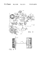
- FIG. 1 shows the electronic lock positioned on the door of a safe or vault and shows the location of the display and the knob of the lock with no markings as are conventional on mechanical combination locks.
- FIG. 2 is a schematic diagram of the lock and its associated electronics.
- FIG. 4 is a side view of the lock.
- FIG. 6 is a continuation of the functional diagram of FIG. 5 .
- FIG. 8 is a logic flow diagram showing a functional flow chart for the Power Down subroutine.
- FIGS. 10 and 11 show the logic flow diagrams representing the subroutine operations that control the electronics when two combinations are required to open the lock.
- FIG. 12 is a logic flow diagram showing the logic control operations that tabulate the number of times errors occur in attempting to open the lock, and the preventing of the opening of the lock if the number of erroneous attempts exceeds a predetermined number, with the resulting lock out of the opening commands, if the correct combination is entered.
- FIGS. 13-17 are flow diagrams expanding operations illustrated in the previous figures.
- FIG. 18 shows a logic flow diagram representing the functional logic that prevents the lock from opening if the knob is left unturned for a pre-selected time without entry of the entire combination.
- FIG. 19 is a logic flow diagram representing the logic control of the electronic lock to detect whether the knob of the lock has been turned more than 480 degrees without the knob stopping for a period of more than a predetermined amount.
- FIG. 20 is a logic flow diagram representing the logic control operations to detect the stopping of the knob and the timing of the stop, and if the stop time is sufficient to recognize the numbers displayed as a combination element.
- FIGS. 21 and 22 are logic flow diagrams that illustrates the logic control operations of the microprocessor to convert the speed of the knob rotation into a rate of incrementation of the displayed number.
- FIGS. 23A and 23B are logic flow diagrams that shows the logic control operations to permit the recovery from a condition where the number displayed is past the target number by less than or equal to 4 and allows the operator to reverse the display sequence and return to a number that is four units prior to the displayed number and to approach the target number again.
- FIG. 24 is a functional diagram showing turning off the knob position sensor when power is generated.
- FIG. 26 is a logic flow diagram illustrating the logic and operations which enable the microprocessor to set a flag indicating that the lock security was compromised by an unauthorized bolt movement.
- FIG. 27 is a flow diagram showing the microprocessor setting a flag indicating that the operator left the lock in an unsecure condition.
- FIG. 28 illustrates the functional logic used to reset the flag use to indicate that an unauthorized access to the container secured by the lock may have occurred.
- Extending from the housing 22 is a bolt 26 that is used to hold the door 12 shut when extended. Also contained in the housing 22 are the mechanical linkages and mechanisms which retract or extend the bolt 26 of the lock 10 .
- An example of the preferred mechanical mechanism is disclosed in U.S. Pat. No. 5,881,589.
- a generator 29 may be connected through a clutch and gear train 28 to knob 14 .
- Generator 29 may generate the electrical power required by the electrical components of lock 10 .
- Generator 29 may be a stepper motor, a conventional AC or DC generator, a battery, or any other power source that could provide the power required by the electrical circuits used to operate lock 10 .
- lock 10 may be powered by an external power source, including, but not limited to, AC or DC line power, external battery, or other external signal that the lock 10 could convert into electrical power.
- Such external signals could include light, infrared, radio, or other signals in the electromagnetic spectrum.
- Either knob 14 , retractor drive 30 , or shaft 20 typically interfaces with position detector 31 .
- Detector 31 will typically have a rotation indicator 32 and at least one sensor 34 .
- the rotation indicator 32 may trigger the first sensor 34 a so that the amount of knob rotation may be determined.
- a second sensor 34 b may be employed when it is desired to know the position of retractor drive 30 with increased accuracy, for example, prior to rotating partial gear 48 .
- Detector 31 may use a segmented magnet as the rotation indicator 32 and a GMR for sensor 34 .
- Sensor 34 may be a device that can act as a switch.
- the display 18 may be a Liquid Crystal Display or LCD device, which has the advantage of being a relatively low consumer of electrical power. Low power consumption may be a consideration when power is generated by the rotation of the knob 14 and the quantity of power generated may be relatively small when stored within the components of the electronics of the power control components 36 .
- one device for withdrawing the bolt uses an output from microprocessor 44 to a latch motor 46 .
- Motor 46 acts to rotate a partial gear 48 to position the partial gear in a position whereby it may be driven rotationally by a series of gear teeth on the periphery of the retractor drive 30 .
- the partial gear will mesh with the drive 30 and be driven by the rotation of the knob 14 .
- the partial gear in turn, will drive a coaxially disposed second gear 50 .
- the second gear 50 is driven by a pin/slot, lost motion, arrangement wherein the second gear 50 carries a pair of pins that reside in a pair of slots formed into the partial gear 48 .
- the rotation of the partial gear 48 is a lost motion rotation for a short portion of the movement, at which point the pins and the slot ends are engaged to provide a positive drive of the second gear 50 .
- the second gear is meshed with an idler gear 52 .
- the idler gear 52 further is meshed and mated with a rack 58 , which either is attached to or forms a portion of the bolt 26 of the lock 10 .
- the partial gear 48 is disposed in a position whereby the teeth on the retractor drive 30 cannot engage the teeth on the partial gear 48 .
- other devices for withdrawing and extending the bolt may be employed.
- An example of another device includes, but is not limited to, that shown in U.S. Pat. No. 5,487,290.
- the microprocessor 44 may be any suitable microprocessor manufactured and sold on the market.
- the lock 10 may utilize a microprocessor designated 80C51F and manufactured and sold by Oki Electric Industries Company, Ltd, of Tokyo, Japan.
- microprocessor 44 The operation of the microprocessor is represented by the flow diagram of FIG. 5 .
- the following description will explain the microprocessor 44 logic operations and flow as the lock 10 is operated.
- terminator 800 the system begins functioning when the generator 29 provides sustaining power to the electronic logic or microprocessor 44 . This is represented by terminator 800 .
- the system may initialize the ports, EPROM, LCD, counters, and variables in operation 810 .
- this fixed time period is approximately two seconds.
- the Random Access Memory (RAM) within the microprocessor 44 may be initialized with all bit switches or flags set to their default conditions, or to the conditions required/allowed/provided by the reset switch in operation 810 . These operations condition the system to accept inputs from sensor 34 a of the lock 10 .
- the lock program may be restarted without the lock turning off. This is represented by terminator 862 .
- terminator 862 When a program restart is performed a restart flag may be set in operation 812 . This flag controls the initialization process of operation 810 . The program flow then moves to operation 814 .
- the microprocessor 44 in operation 814 checks to see if the lock 10 has been attacked by checking the “CE” and “SA” flags and then generating a signal that may display a “CA”, “SA”, “CE”, or “SC” on display 18 .
- the “CA” indicates that the lock 10 is ready to accept a combination element entry.
- the other three codes indicate that the lock 10 has been attacked in some manner and that the lock 10 must be reset. Alternatively, other symbols could be used to indicate if the lock had been attacked. Furthermore, display of a code or symbol is not required and could be omitted.
- decision 816 a determination is made as to whether this startup is the result of a power on entry or a restart entry of the lock program.
- One method of checking for a power on entry is to check to see if the restart flag or bit is set to “NO”. If this operational sequence of the system is due to power on, the flow is to decision 818 where the microprocessor 44 checks to see if the generator 29 is still producing power. If the generator 29 is not producing any power the flow branches to decision 822 . When the generator 29 produces power, the microprocessor 44 checks to see how long the power has been produced in decision 819 . If the generator has produced power for longer than a predetermined time period, for example, 2.8 seconds, then the audit and seal counters may be displayed, in operation 820 .
- a predetermined time period for example, 2.8 seconds
- decision 818 and operation 820 both converge on decision 822 where it is ascertained if the error counter is equal to or exceed a predetermined number, typically 3 or more. If not, the flow branches around operation 824 to decision 826 . If the error counter contains a count of 3 or more, the flow is to operation 824 where the number of errors may be displayed. Thus, showing the operator the number of unsuccessful attempts made to open the lock since the last successful entry.
- microprocessor 44 checks to see if the watchdog flag is set.
- the watch dog flag when set indicates that the lock has been left with the knob 14 unmoved for a fixed period of time, for example, five seconds. If the flag is set, then the lock may turn off by the Power Down subroutine represented by terminator 1200 .
- the flow may move to operation 827 .
- a symbol may be displayed to prompt the operator to begin entering the combination, for example, “E 1 ” may be displayed, and then the processor waits for the knob 14 to rotate.
- the microprocessor 44 may wait until the knob 14 rotates in the clockwise direction and the sensor 34 a sends at least a predetermined number of signals to microprocessor 44 before displaying any numbers.
- the knob may rotate before displaying numbers on display 18 .
- the processor 44 may wait a random time period, typically between zero and two seconds while the knob rotates before displaying numbers on display 18 . This random delay time inhibits the ability of an observer to correlate knob position with the combination entered.
- the NUM 2 switch may be “ON” or set.
- the microprocessor 44 may send a signal to display a “00” and the NUM 2 switch would be changed to “OFF”. If the NUM 2 switch is “OFF” a signal may be sent to display a “50” on LCD display 18 and the NUM 2 switch would be changed to “ON”.
- any other number including a random number could be used instead of the “00” or “50”.
- microprocessor 44 determines if a combination element has been entered. If a combination element was entered, the flow moves to block 830 , which represents the Numbers In subroutine shown in FIG. 9 . Following reentry to the main system flow from FIG. 9, either an “E 2 ” or “E 3 ” may be displayed in operation 832 . An “E 2 ” is displayed to prompt the operator to enter the second combination element and an “E 3 ” is displayed to prompt the operator to enter the third combination element. Alternatively, any other symbol or prompt could be used. In some embodiments it may be desired to blank the display after the entry of a combination element, i.e. no prompt. A blank display 18 may make it more difficult for a person to gain entry with out the authorized combination since the person would not know how many combination elements the lock 10 required.
- decision 828 (“NO” branch) or operation 832 could then move to decision 833 , where the watch dog flag is checked. If the watch dog flag is set, “ON,” then the lock may turn off at terminator 1200 using the Power Down subroutine.
- the microprocessor 44 may check the display switch in decision 834 . If the display needs to be updated due to knob rotation or program function, the display switch or bit is “ON”. When display 18 shows up-to-date information, the display switch or bit is “OFF”. With the display switch “ON” the flow moves to operation 836 which represents the Display.Flo subroutine shown in FIG. 7 . Alternatively, any other method of updating the display 18 may be employed.
- the flow enters operation 838 where the microprocessor 44 may check the voltage to ensure sufficient power is available to operate lock 10 . Thereafter the flow loops back to decision 828 discussed above.
- Display.Flo Controls the display 18 ; 2) Power Down—shuts off the power to proessor 44 ; and 3) Numbers In—process the combination numbers.
- the Display.Flo subroutine 836 is discussed first.
- Block 836 of FIG. 6 is further expanded in FIG. 7 .
- the Display Flo subroutine 836 converts the number/character data into a format that can be utilized by the display selected. Referring to FIG. 7, the flow enters at block 836 and then converts the tens data to segment data in operation 1100 .
- the display 18 displays characters and/or numbers made up of segments that are turned on or turned off and the ones turned on in conjunction with the others turned off form contrasting bars against the background of the display, making visible characters and/or numbers.
- This operation 1100 converts, through a table look up, the character and/or number in the tens position of the display, to data bits, ones and zeros, necessary to turn on or off the segments of the display in the tens position.
- decision block 1212 the microprocessor 44 waits for the timer set in operation 1208 or 1210 to expire. Thereafter, microprocessor 44 turns off when the power supply is dropped in operation 1214 .
- the lock-operating program could resume with a power on entry illustrated by terminator 800 (FIGS. 5 and 8 ).
- the microprocessor 44 could test for power generation between decision 1212 and operation 1214 . In this case, if no power generation was detected the microprocessor 44 would be shut down. When power was being generated, however, the lock could restart at terminator 862 at FIG. 5 . The above alternative may provide for faster lock response in some situations.
- Block 830 represents entry into the Numbers In subroutine.
- the numbers in the combination counter, and shown on the display 18 may be saved as an element of the combination in operation 850 .
- the program logic checks for entry of all elements of the combination in decision 852 .
- a combination may use three combination elements.
- the lock may be programmed to use any number of elements desired. A larger number of combination elements results in a larger number of possible combinations. The larger the number of possible combinations tends to result in a higher level of lock security. If all elements have not been entered, then the flow returns to the main program flow.
- the ports 62 of microprocessor 44 may be checked to see of the change key 60 has been inserted. If the change key 60 has been inserted into the ports 62 , then the flow may move to block 864 which represents the subroutine shown in FIG. 13 . Upon completion of the routine of FIG. 13, the may move to the power down subroutine represented by terminator 1200 .
- the microprocessor 44 When the error counter is equal to or exceeds the predetermined number, the microprocessor 44 will set the SA detect switch “ON” in operation 422 . Thereafter, the flow may move to operation 424 where an error symbol may be displayed.
- a lightning bolt is an example of one symbol that may be utilized as an error symbol. Thence, the program flow may return to the main flow.
- This subroutine may be employed to change the combination for the electronic lock.
- the mode of the lock may check to see if a second combination is required to open the lock, in decision 900 . If not, the flow branches around operation 902 to operation 904 . If a second combination is required to open the lock, then the second combination may be obtained in operation 902 , from the knob input as discussed above for FIGS. 5-11.
- the type or mode of operation for lock 10 may be selected, for example, as either single, dual or senior/subordinate mode in operation 904 .
- decision 906 moves the flow is to operation 908 which represents the Single.Flo subroutine shown in FIG. 14; when the routine in FIG. 14 is complete, the flow returns to the main program flow where the new combination is acquired.
- the new combination may be required to be entered on the same power cycle.
- the flow is to block 912 which represents the Dual Combo.Flo subroutine of FIG. 15, and when that subroutine is complete, the flow returns to the main program flow where the operator(s) enter two combinations.
- Some embodiments of lock 10 may utilize only a single combination to open the lock. Consequently, only block 908 could be employed to change the combination.
- block 908 represents the Single.Flo subroutine illustrated in FIG. 14 .
- block 908 is expanded into a subroutine and when the subroutine in FIG. 14 is complete, the flow returns to FIG. 13 .
- operation 1054 may provide a message to the operator prompting the operator to pull out the change key 60 from the ports 62 .
- One message that may be displayed is “PO”.
- any other message could be used to prompt the operator in operation 1054 .
- the microprocessor may not provide any signal and may wait for the operator to remove the change key 60 .
- the electronic control may then wait in operation 1056 until the change key 60 has been removed from ports 62 .
- the removal of the change key may signify the completion of the combination change.
- the control logic flow may progress to operation 1058 where the new combination flag may be written into memory. Thereafter, the flow may return to the flow of FIG. 13 where the operator may be prompted to confirm the combination by entering the new combination. If the combinations do not match, then the new combination may not be saved and the operator may repeat the combination change process. When the combinations match the new combinations may be saved as the new authorized combination for the lock. Alternatively, the combination entered may be saved without verifying the changed combination.
- SA-CE switch If the SA-CE switch is “OFF” then the flow may continue to decision 409 where the status of the surreptitious attempts (SA Detect) switch is checked. If the SA Detect switch is ON, then the flow may move to the Lightening Error sub-routine represented by terminator 860 . When the SA Detect switch is OFF the flow may continue to block 411 where the valid try counter could be reset.
- SA Detect the status of the surreptitious attempts
- microprocessor 44 determines if the lock 10 is in the dual combination mode in decision 874 .
- the combination match is checked in decision 876 and if the combination does not match either authorized combination, the error flag is checked at decision 877 and if ON the lightning bolt is displayed in the Lightning Error Subroutine represented by operation 860 and the error counter updated. The error flag is then reset in operation 861 .
- the flow branches the Process Numbers Senior Mode flowchart represented by terminator 875 .
- the flow from terminator 875 continues on FIG. 11 .
- the change key 60 may be detected in decision 888 .
- the flow may move to the GetCombo.Flo subroutine represented by block 864 . Thereafter, the flow could move to the Power Down subroutine represented by terminator 1200 , all previously described.
- the combination is compared in decision 890 to the senior combination. If the senior combination matches, then the senior combination flag is toggled on/off in operation 892 . This either enables the subordinate combination or disables the acceptance of the subordinate combination respectively.
- the message “PO”, standing for Pull may be displayed on the display 18 to inform the operator to pull the change key 60 from ports 62 .
- the change key symbol may be turned off and a message “CC” could be displayed to prompt the operator to confirm the combination(s) by entering the new combinations(s). Thence, the bolt 26 may be retracted and the new combination(s) may be stored in combination memory, completing the change of combination operation.
- operation 1010 may continue to sample the ports 62 to determine whether the change key 60 has been removed. The looping and sampling could continue until the key 60 is confirmed as removed, whereupon, in operation 1012 , the write new combination flag is set and the flow may return to the flow in FIG. 17 at operation 914 .
- a dialer attacks a combination lock by dialing combinations until the lock opens.
- a dialer In order to open a lock in a short time period a dialer typically rotates the dial rapidly. Consequently, it is desirable to slow down the entry of lock combinations. By slowing the acceptable entry of a combination, it insures that the lock may statistically withstand such an assault for a longer time. If a dialer were devised to overcome some or all of the other safeguards and features of the lock, slowing the acceptable entry rate reduces the number of entries that may be attempted in a given period of time. Time is an enemy of the attacker, and exposes them to detection. Thus, anything that will delay the attackers success is useful.
- the electronic lock 10 is provided with a timer within the microprocessor 44 , which may wait a fixed time period, for example, two seconds after power-on, before entry of the first number of the combination. Additionally, this wait may be required after the entry of each subsequent number of the combination. Therefore, the total mandatory wait time could be eight seconds.
- the internal clock timer of the microprocessor 44 may be started at power-on when the microprocessor 44 is supplied sufficient power from the power control 36 to operate the electronics 24 . After the lock 10 has received power for the fixed time period the lock electronics 24 may then accept the entry of the first combination number. After the entry of each subsequent combination number there may also be a wait period. Thus, the lock 10 may not be entered in less than eight seconds and since, from a practical standpoint, it will take additional time to rotate the knob to the proper number, it is unlikely that the lock could be opened in less than 10 seconds by someone who know the proper combination. This feature reduces the effectiveness of an attack with a dialer.
- the lock may be opened or a change of combination effected, as previously discussed.
- the logic of the fast entry feature is shown in FIG. 20 .
- a common and serious security violation is to enter the first two numbers of a combination so that the third number may be entered at a later time with a minimum of delay in accessing the enclosure. This practice allows one who knows only the last number of a combination to access the enclosure.
- FIG. 18 illustrates the function of this feature combined with the fast entry prevention feature of lock 10 .
- the feature may start after the display of “E 1 ”, “E 2 ”, or “E 3 ” as shown in FIGS. 5 and 6. Alternatively, this feature could start when the lock 10 is ready to accept the input of a combination element.
- Block 250 represents these prior actions.
- a timer is set to the period of time selected for this feature in operation 252 . One time period may be five seconds.
- the microprocessor may check for knob 14 rotation followed by a stop in decision 254 .
- the logic could permit the main program logic to enter the combination element in operation 255 . Thereafter the logic loops back to just prior to operation 252 to reset the timer.
- the flow of operations may be from decision 254 to decision 256 where the unattended timer is polled to see if the number entry stop time period may have expired. If it has expired, then the combination element has not been entered within the allotted time and the lock 10 could shut down with the Power Down subroutine represented by terminator 1200 . This operation is on an interrupt basis and after the operation, the overall system operation continues unless the lock 10 has been shut down.
- the flow branches from decision 256 back to the main system operation as the interrupt is completed. Periodically, the main system flow is interrupted to check on the timer and knob status. This check is indicated by the loop back to decision 254 .
- knob 14 of the lock 10 results in the knob 14 being turned a partial turn and the knob 14 stopped and the hand repositioned to attain a new grasp of the knob 14 prior to the next turn. If the knob 14 turns more than what a normal hand/wrist will permit, the lock could be operated by a dialer or similar device. To sense this and to prevent the lock 10 from opening, the amount of knob rotation without a stop may be detected. This feature of the invention is illustrated in FIG. 19, which is a more detailed expansion of operation 414 of FIG. 16 .
- the signals from the sensor 34 a are monitored and it is determined whether the knob 14 has stopped turning, in decision 302 . If the determination of decision 302 is that the knob 14 has not stopped turning, then the logic control flow loops back to just prior to decision 302 and the signal output of the sensor 34 a is again monitored. This loop continues until the knob 14 is detected as having stopped turning.
- the logic flow branches out of the loop to decision 304 where the number of signals/pulses generated since the last knob stop is determined and compared with a fixed number of pulses.
- the fixed number of pulses could be the number of pulses sent by sensor 34 during rotation of the knob 14 by at least 1.33 turns or at least 480 degrees.
- the operation of the lock 10 by a person may not be inhibited, while the operation of the lock 10 by a dialer or other similar device could be inhibited because the lock will not respond to the correct combination after the knob is rotated for more than the predetermined number of pulses from sensor 34 a without stopping.
- the lock 10 could be provided with a scheme of varying the number of pulses from knob position sensor 34 that are required to update the display 18 to cause it to display the next larger number.
- the benefit of this scheme is that as the speed of rotation of the knob 14 of the lock 10 increases, the rate of change of the displayed numerals increases until the rate of change is set by the fastest rotational rate and then the relationship of the rate of change of the displayed characters and/or numbers to the number of pulses from the knob position detector 31 remains constant for the remainder of that rotational movement of the knob 14 , until the knob stops, even if the rotational speed of the knob slows during later stages of rotation this feature reduces the correlation of the number change rate on the display 18 and the extent of rotation of the knob 14 .
- FIG. 21 is a flow diagram which represents the decisions made by the microprocessor 44 on an interrupt basis to determine the speed at which the knob 14 is being turned, which then may be used to set rates at which the numbers are changed.
- the knob position detector 31 outputs pulses on lines 38 and 40 .
- the phase 1 line 38 conveys pulses, which are used to indicate rotational displacement of the knob 14 .
- the knob position detector may be configured such that a full rotation of the knob 14 may cause the sensor 34 a to send a number of signals/pulses. This number could be approximately 28 pulses. The number of pulses sent by the knob position detector 31 , however, could vary depending on the indicator 32 and sensor 34 selected.
- the pulses on the phase 1 line 38 may be connected to an interrupt bit in the microprocessor 44 . Accordingly, each pulse may interrupt the microprocessor 44 .
- the interrupt may be used to start and stop timers and counters.
- a further filter to eliminate spurious conditions which could lead to unreliable results is that the middle and high speed indicators in the microprocessor 44 could be locked out or rendered ineffective unless at least a predetermined number, for example 10 , phase 1 pulses have been detected by the microprocessor 44 since the last valid knob stop.
- This filtering of the inputs insures that the middle and high-speed operation of the display 18 is prevented during quick short burst rotation of the knob 14 .
- the microprocessor 44 has within it a counter that could be designated as the combination counter, which counts the numbers and the numbers are displayed on display 18 , as well as being available for the internal processing of the number and/or character for use in the combination.
- the combination counter may be incremented, based on the number of pulses received by the microprocessor 44 .
- the number of pulses can vary based on the knob speed as decided by the voting scheme described above.
- the lock out flag may set during the actual opening cycle of the lock 10 (turning the knob 14 to retract the bolt 26 from strike 56 ), to inhibit the bolt 26 from being retracted if the knob 14 is turned too fast. If the bolt 26 is engaged with the bolt retractor 50 when the knob is being turned too fast, physical damage, binding, or malfunction in the mechanical bolt retraction assembly may result.
- the incrementing of the combination counter may be accomplished for the first four pulses of a turn in the low speed and then thereafter with each seven pulses. This scheme provides the operator a visual feedback early in the operation at these speeds and then slows the incrementing to the desired rate thereafter, for the same knob turn.
- the counter and the display could be incremented by one unit for each 2.5 pulses if the interpulse time interval is less than 2.5 msec but more than 7.5 msec and the middle speed flag is set.
- all numbers and/or characters may be sent to the display 18 . Due to the response time of the display and the ability of the human eye to receive and process images only at relatively slow speeds, it may appear that numbers are being skipped by the display 18 . Alternatively, in the high-speed mode not all numbers could be sent to display 18 resulting in skipped numbers but faster response.
- the interpulse time period may be determined by the detection and voting scheme described above. Thus, the time value could be compared in decision 450 to the time interval standard for the lock out mode, i.e., 7.5 msec, and if the interpulse time is less than the standard, the lock out speed flag is set in operation 452 . Following the setting of the lock out speed flag, the high speed flag may be set in operation 456 . When the interpulse time standard for the high speed flag is longer than that selected for the high speed lock, then the high speed interpulse time would be checked in decision 454 . If the measured interpulse time is less than that specified for the high speed flag in decision 454 , then the high speed flag could be set :in operation 456 .
- the flow is from decision 454 or 450 to decision 458 where the interpulse time period could be compared to the middle speed time standard.
- the flow branches to operation 460 where the middle speed flag is set.
- the interpulse time period may be compared to the slow speed time standard and the appropriate speed flags set.
- the setting of a speed flag results when the flow is diverted from the series of decisions 450 , 454 , 458 , and 462 .
- the flow is then through flag setting operations 452 , 456 , 460 , and 464 as appropriate with the resulting setting of all flags for speeds slower that the first satisfied speed condition.
- the interpulse time interval is greater than a preprogrammed time, for example, 129.15 msec, then the only remaining choice of speeds may be creep speed and the creep speed flag is set in operation 466 .
- the flow from operation 466 could be back to the main flow of the program.
- the microprocessor 44 may update or increment the combination counter. This updating may be accomplished by the logic control operations represented by the flow diagram of FIG. 22 illustrating of the Count.Flo subroutine.
- the flags of the microprocessor 44 may be checked to ascertain if the speed has been determined by the voting scheme as described above.
- the microprocessor 44 could check the high-speed flag in decision 502 . If the high speed flag is set, the microprocessor 44 could update the combination counter by one unit for each pulse received from the knob position sensor 34 a , as represented by operation 504 . If the high-speed flag has not been set then the middle speed flag may be tested to see if it has been set in decision 506 . When the middle speed flag has been set, as determined in decision 506 , the combination counter could be updated by two units for each five pulses as represented by operation 508 .
- a decision 510 may be made as to whether this could be the initial knob rotation at a low speed in this knob turn. If this decision operation results in a negative determination, then the knob 14 may have been rotated at a low speed previously in this knob turn and the combination counter may be incremented by one unit for each 'seven pulses sent by the knob position sensor 34 , as represented by operation 512 .
- this feature may permit an operator to recall and reenter the previous combination element.
- This second back up feature may be utilized by reversing the rotation of knob 14 after entering a combination element and before rotating knob 14 to enter a subsequent combination element.
- the operator may turn the knob 14 too far and pass the target number of the combination. While the knob 14 may be turned additional revolutions and the target number selected and displayed, the lock may permit the operator to reverse the knob direction for a short displacement with the combination element displayed and contained in the combination counter changed by a predetermined amount. After the combination element backs up, the knob 14 may then be turned in the clockwise direction to again approach the target number and/or character of the combination.
- the logic control of this function uses two interrupt routines illustrated in FIGS. 23A and 23B.
- the flow may move to the remaining program flow where the combination for the lock is allowed to be entered as discussed previously.
- the combination of the error and audit counters provide a reliable, easily accessed, easily understood indication that the lock has been operated; and if the numbers are different, may indicate failure or success by the attacker.
- the serial number of the lock may be used as a temporary combination to open the lock and thus allow the setting of a new combination. This allows for circumstances where locks are placed in inventory and records of combinations are misplaced or memories lapse and no one remembers the combination of an inventory lock.
- the open flag in the memory of the microprocessor 44 is checked in operation 654 . If the open flag is on, the serial number is not allowed by operation 656 as a combination, because the lock is open and was presumably opened with a correct and known combination. However, if the open flag or bit is not on, indicating that the lock 10 is locked, then the lock 10 is conditioned to accept the serial number of the lock 10 as a substitute combination, in operation 658 . This may be accomplished by the setting of a flag which then allows the comparing of the serial number which is stored in a memory associated with microprocessor 44 , with the entered combination, rather than comparing the authorized combination.
- microprocessor 44 When the bolt power supply is “ON”, microprocessor 44 can be turned on due to the bolt movement. Therefore, the microprocessor 44 may check the status of bolt 26 in decision 1422 . If the bolt is open, then the flow moves to decision 1424 where microprocessor 44 checks the bolt open switch. If the bolt open switch is “ON”, then the lock 10 may power down. The bolt 26 open with the open switch “ON” is a normal condition and the microprocessor 44 is not required to take any action.
- the microprocessor 44 will also check the bolt open switch in decision 1426 . If the bolt open switch is “ON”, then the microprocessor may power down. The bolt extended and the bolt open switch “ON” is also a normal condition and microprocessor is not required to take any further action and the bolt open switch will be reset and the lock powered down.
- the microprocessor 44 may set the CE flag “ON” and shut down in terminator 1428 .
- lock 10 when the lock 10 is powered by the rotation of generator 29 as represented by terminator 1400 , and “CE” is displayed on display 18 , represented by block 1402 lock 10 may be reset before opening lock 10 or the CE lock out feature bypassed.
- the microprocessor 44 checks to see if the lock 10 was powered a minimal time, for example, greater than 2.8 seconds as shown in operation 1406 . If the lock 10 was not powered for this minimum time then the lock 10 may permit a combination to be entered. This entry however, may not open the lock 10 .
- the error and audit counters may be displayed as discussed above.
- the operator can enter one or more numbers, characters and/or symbols, typically “99”, and the “CE” reset combination as shown in block 1408 .
- the number, “99” in this case, may serve as a trigger that a reset combination is being entered.
- the lock 10 will check the “CE” reset combination for a match in operation 1410 .
- the “CE” detect flag is reset and the SA-CE switch is set “ON” if the SA detect flag is “ON” in block 1412 . If the combinations do not match the operator must start the reset process from the beginning.
- lock 10 may be reset in order to employ the authorized combination to open lock 10 .
- the microprocessor 44 could check to see if the lock was powered a minimal time, for example, greater than 2.8 seconds, as shown in decision 1304 . If the lock was not powered for this minimum time then the lock may permit a combination to be entered. This entry, however, may not open the lock 10 .
- the error and audit counters may be displayed as discussed above. Then the operator can enter one or more numbers, characters and/or symbols, typically “99”, followed by the “CE” reset combination as shown in block 1308 followed by the authorized combination in block 1312 .
- the microprocessor may check to ensure that both combinations were entered in the same power cycle in operation 1310 . If the lock turns off then the proceeding steps may be repeated when the lock 10 again is powered.
- the lock 10 will check the combinations for a match also in operation 1312 . When there is a match then the “SA” detect flag can be reset in operation 410 of FIG. 16 . If the combinations do not match, the operator may start the reset process from the beginning.
- the exemplary embodiment of this invention implements the control operations and hence the functions and operational features of the lock 10 in microcode in a microprocessor 44 of the type sold by OKI Electric Industries Company, Ltd., under the designation 80C5IF.
- Other microprocessors by other manufactures may be substituted for the preferred device so long as the characteristics of the substituted device meet the needs of the lock 10 .
- the control of the microprocessor 44 is by microcode which is written according to the constraints defined by the device manufacturer and which are readily available from the device manufacturer of choice. Any skilled code writer may code the microcode, given a program listing. The program listing may be prepared for the device of choice, following the constraints required by the particular microprocessor device chosen.
- the logic and operational flow diagrams contained in FIGS. 5-29 are applicable to any microprocessor and accordingly, teach one of skill in programming the necessary operations to operate the lock.
- the organization of the logic flows is exemplary and may be modified according to the desire of the programmer and code writer.
Abstract
Description
| SPEED CHART |
| SPEED | TIME INTERNAL BETWEEN | PULSES PER |
| FLAG | PULSES MINIMUM | COMBINATION COUNT |
| Lock out | 7.5 msec | 1 |
| High | 7.50 msec | 1 |
| Middle | 25.00 msec | 2.5 |
| Low | 129.15 msec | 4-7 |
Claims (6)
Priority Applications (1)
| Application Number | Priority Date | Filing Date | Title |
|---|---|---|---|
| US09/419,948 US6741160B1 (en) | 1998-10-20 | 1999-10-18 | High security electronic combination lock |
Applications Claiming Priority (2)
| Application Number | Priority Date | Filing Date | Title |
|---|---|---|---|
| US10495598P | 1998-10-20 | 1998-10-20 | |
| US09/419,948 US6741160B1 (en) | 1998-10-20 | 1999-10-18 | High security electronic combination lock |
Publications (1)
| Publication Number | Publication Date |
|---|---|
| US6741160B1 true US6741160B1 (en) | 2004-05-25 |
Family
ID=32314259
Family Applications (1)
| Application Number | Title | Priority Date | Filing Date |
|---|---|---|---|
| US09/419,948 Expired - Lifetime US6741160B1 (en) | 1998-10-20 | 1999-10-18 | High security electronic combination lock |
Country Status (1)
| Country | Link |
|---|---|
| US (1) | US6741160B1 (en) |
Cited By (24)
| Publication number | Priority date | Publication date | Assignee | Title |
|---|---|---|---|---|
| US20020019947A1 (en) * | 2000-07-31 | 2002-02-14 | Matsushita Electric Industrial Co., Ltd. | Discernment information input apparatus |
| US20070006328A1 (en) * | 2005-06-29 | 2007-01-04 | Asian Integration Co., Ltd. | Electronic storage box, opening and closing method of electronic storage box, and computer program product thereof |
| US20070056339A1 (en) * | 2005-09-13 | 2007-03-15 | Christopher Irgens | Combination lock |
| US20070115094A1 (en) * | 2004-03-12 | 2007-05-24 | Joachim Gillert | Locking cylinder and closing method |
| US20070257773A1 (en) * | 2006-04-26 | 2007-11-08 | Compx International Inc. | Field retrofittable refrigerator lock with audit trail |
| US20070268132A1 (en) * | 2006-05-18 | 2007-11-22 | T.K.M. Unlimited, Inc. | Door accessory power system |
| US20090015244A1 (en) * | 2005-07-21 | 2009-01-15 | Oliver Zegula | Control element for a motor vehicle |
| US20100188190A1 (en) * | 2007-07-18 | 2010-07-29 | Iloy Oy | Electromechanical lock |
| US20110012709A1 (en) * | 2009-07-14 | 2011-01-20 | Compx International Inc. | Method and system for data control in electronic locks |
| US20110187495A1 (en) * | 2010-02-01 | 2011-08-04 | Ping-Hsun Weng | Electric release fastening device for thin-profile space |
| US20140218168A1 (en) * | 2013-02-07 | 2014-08-07 | Schlage Lock Company Llc | Multi-control entry door hardware |
| US9245104B2 (en) | 2014-01-10 | 2016-01-26 | Here Global B.V. | Method and apparatus for providing security with a multi-function physical dial of a communication device |
| US20160054714A1 (en) * | 2013-03-15 | 2016-02-25 | Sargent Manufacturing Company | Electronic circuit to capture lock controller pulses |
| WO2016100289A1 (en) | 2014-12-15 | 2016-06-23 | Sargent & Greenleaf, Inc. | Non-intrusive dial rotation detection of high security locks |
| US20160260274A1 (en) * | 2013-10-24 | 2016-09-08 | Utc Fire & Security Americas Corporations, Inc. | Systems and methods for locking device management including time delay policies using random time delays |
| US20160298362A1 (en) * | 2015-04-08 | 2016-10-13 | Klaus W. Gartner | Method and device for inputting an access code in an electronic combination lock |
| WO2016196192A1 (en) | 2015-06-05 | 2016-12-08 | Sargent & Greenleaf, Inc. | High security electromechanical lock |
| US20170051532A1 (en) * | 2014-04-29 | 2017-02-23 | Hao Min | Electronic-mechanical dual control lock |
| US10127745B2 (en) | 2014-12-29 | 2018-11-13 | Invue Security Products Inc. | Merchandise display security systems and methods |
| CN110262468A (en) * | 2019-07-26 | 2019-09-20 | 泰华智慧产业集团股份有限公司 | Smart lock test equipment and test method |
| CN111519995A (en) * | 2020-04-29 | 2020-08-11 | 德施曼机电(中国)有限公司 | Intelligent fingerprint door lock device |
| US11157789B2 (en) | 2019-02-18 | 2021-10-26 | Compx International Inc. | Medicinal dosage storage and method for combined electronic inventory data and access control |
| US11176765B2 (en) | 2017-08-21 | 2021-11-16 | Compx International Inc. | System and method for combined electronic inventory data and access control |
| WO2023136912A1 (en) * | 2022-01-14 | 2023-07-20 | Lock Ii, Llc | Electromechanical locks and related methods |
Citations (6)
| Publication number | Priority date | Publication date | Assignee | Title |
|---|---|---|---|---|
| US4917022A (en) | 1988-09-29 | 1990-04-17 | Olympic Co., Ltd. | Safe having motor-driven locking mechanism |
| US5061923A (en) | 1988-09-29 | 1991-10-29 | C & M Technology, Inc. | Computerized combination lock |
| US5517184A (en) | 1991-06-21 | 1996-05-14 | C & M Technology, Inc. | Electronic combination lock with high security features |
| US5684457A (en) | 1995-06-01 | 1997-11-04 | C&M Technology, Inc. | Tamper indication system for combination locks |
| EP0851080A2 (en) | 1996-12-19 | 1998-07-01 | Mas-Hamilton Group | Emitter and power drive system for an electronic lock |
| US5881589A (en) | 1997-06-12 | 1999-03-16 | Mas-Hamilton Group | Gear driven bolt withdrawal for an electronic combination lock |
-
1999
- 1999-10-18 US US09/419,948 patent/US6741160B1/en not_active Expired - Lifetime
Patent Citations (8)
| Publication number | Priority date | Publication date | Assignee | Title |
|---|---|---|---|---|
| US4917022A (en) | 1988-09-29 | 1990-04-17 | Olympic Co., Ltd. | Safe having motor-driven locking mechanism |
| US5061923A (en) | 1988-09-29 | 1991-10-29 | C & M Technology, Inc. | Computerized combination lock |
| US5517184A (en) | 1991-06-21 | 1996-05-14 | C & M Technology, Inc. | Electronic combination lock with high security features |
| US5777559A (en) * | 1991-06-21 | 1998-07-07 | C & M Technology, Inc. | Electronic combination lock with high security features |
| US5973624A (en) | 1991-06-21 | 1999-10-26 | C & M Technology, Inc. | Electronic combination lock with high security features |
| US5684457A (en) | 1995-06-01 | 1997-11-04 | C&M Technology, Inc. | Tamper indication system for combination locks |
| EP0851080A2 (en) | 1996-12-19 | 1998-07-01 | Mas-Hamilton Group | Emitter and power drive system for an electronic lock |
| US5881589A (en) | 1997-06-12 | 1999-03-16 | Mas-Hamilton Group | Gear driven bolt withdrawal for an electronic combination lock |
Cited By (49)
| Publication number | Priority date | Publication date | Assignee | Title |
|---|---|---|---|---|
| US20020019947A1 (en) * | 2000-07-31 | 2002-02-14 | Matsushita Electric Industrial Co., Ltd. | Discernment information input apparatus |
| US20070115094A1 (en) * | 2004-03-12 | 2007-05-24 | Joachim Gillert | Locking cylinder and closing method |
| US8456277B2 (en) * | 2004-03-12 | 2013-06-04 | Dom-Sicherheitstechnik Gmbh & Co. Kg | Locking cylinder and closing method |
| US7671719B2 (en) * | 2005-06-29 | 2010-03-02 | Asian Integration Co., Ltd. | Electronic storage box, opening and closing method of electronic storage box, and computer program product thereof |
| US20070006328A1 (en) * | 2005-06-29 | 2007-01-04 | Asian Integration Co., Ltd. | Electronic storage box, opening and closing method of electronic storage box, and computer program product thereof |
| US7852071B2 (en) * | 2005-07-21 | 2010-12-14 | Preh Gmbh | Control element for a motor vehicle |
| AU2006271877B2 (en) * | 2005-07-21 | 2010-09-16 | Preh Gmbh | Operating element for a motor vehicle |
| US20090015244A1 (en) * | 2005-07-21 | 2009-01-15 | Oliver Zegula | Control element for a motor vehicle |
| US20070056339A1 (en) * | 2005-09-13 | 2007-03-15 | Christopher Irgens | Combination lock |
| EP1924754A4 (en) * | 2005-09-13 | 2010-10-06 | Master Lock Co | Combination lock |
| EP1924754A2 (en) * | 2005-09-13 | 2008-05-28 | Master Lock Company LLC | Combination lock |
| US20070257773A1 (en) * | 2006-04-26 | 2007-11-08 | Compx International Inc. | Field retrofittable refrigerator lock with audit trail |
| US7768378B2 (en) * | 2006-04-26 | 2010-08-03 | Compx International Inc. | Field retrofittable refrigerator lock with audit trail |
| US20070268132A1 (en) * | 2006-05-18 | 2007-11-22 | T.K.M. Unlimited, Inc. | Door accessory power system |
| US7522042B2 (en) | 2006-05-18 | 2009-04-21 | T.K.M. Unlimited, Inc. | Door accessory power system |
| US20100188190A1 (en) * | 2007-07-18 | 2010-07-29 | Iloy Oy | Electromechanical lock |
| US8981899B2 (en) * | 2007-07-18 | 2015-03-17 | Iloq Oy | Electromechanical lock |
| US8970344B2 (en) | 2009-07-14 | 2015-03-03 | Compx International Inc. | Method and system for data control in electronic locks |
| US20110012709A1 (en) * | 2009-07-14 | 2011-01-20 | Compx International Inc. | Method and system for data control in electronic locks |
| US8319604B2 (en) * | 2010-02-01 | 2012-11-27 | Ping-Hsun Weng | Electric release fastening device for thin-profile space |
| US20110187495A1 (en) * | 2010-02-01 | 2011-08-04 | Ping-Hsun Weng | Electric release fastening device for thin-profile space |
| US20140218168A1 (en) * | 2013-02-07 | 2014-08-07 | Schlage Lock Company Llc | Multi-control entry door hardware |
| US9443364B2 (en) * | 2013-02-07 | 2016-09-13 | Schlage Lock Company Llc | Multi-control entry door hardware |
| US9977412B2 (en) * | 2013-03-15 | 2018-05-22 | Sargent Manufacturing Company | Electronic circuit to capture lock controller pulses |
| US20160054714A1 (en) * | 2013-03-15 | 2016-02-25 | Sargent Manufacturing Company | Electronic circuit to capture lock controller pulses |
| US20160260274A1 (en) * | 2013-10-24 | 2016-09-08 | Utc Fire & Security Americas Corporations, Inc. | Systems and methods for locking device management including time delay policies using random time delays |
| US9747737B2 (en) * | 2013-10-24 | 2017-08-29 | Utc Fire & Security Americas Corporation, Inc. | Systems and methods for locking device management including time delay policies using random time delays |
| US9245104B2 (en) | 2014-01-10 | 2016-01-26 | Here Global B.V. | Method and apparatus for providing security with a multi-function physical dial of a communication device |
| US9657500B2 (en) * | 2014-04-29 | 2017-05-23 | Nanjing Easthouse Electrical Co., Ltd. | Electronic-mechanical dual control lock |
| US20170051532A1 (en) * | 2014-04-29 | 2017-02-23 | Hao Min | Electronic-mechanical dual control lock |
| WO2016100289A1 (en) | 2014-12-15 | 2016-06-23 | Sargent & Greenleaf, Inc. | Non-intrusive dial rotation detection of high security locks |
| EP3234286A4 (en) * | 2014-12-15 | 2018-08-15 | Sargent and Greenleaf Inc. | Non-intrusive dial rotation detection of high security locks |
| US10127745B2 (en) | 2014-12-29 | 2018-11-13 | Invue Security Products Inc. | Merchandise display security systems and methods |
| US10347061B2 (en) | 2014-12-29 | 2019-07-09 | Invue Security Products Inc. | Merchandise display security systems and methods |
| US10210681B1 (en) | 2014-12-29 | 2019-02-19 | Invue Security Products Inc. | Merchandise display security systems and methods |
| US10107013B2 (en) * | 2015-04-08 | 2018-10-23 | Klaus W. Gartner | Method and device for inputting an access code in an electronic combination lock |
| US20160298362A1 (en) * | 2015-04-08 | 2016-10-13 | Klaus W. Gartner | Method and device for inputting an access code in an electronic combination lock |
| US9874042B2 (en) * | 2015-04-08 | 2018-01-23 | Klaus W. Gartner | Method and device for inputting an access code in an electronic combination lock |
| EP3303738A4 (en) * | 2015-06-05 | 2019-01-09 | Sargent and Greenleaf Inc. | High security electromechanical lock |
| US10415270B2 (en) | 2015-06-05 | 2019-09-17 | Sargent & Greenleaf, Inc. | High security electrochemical lock |
| WO2016196192A1 (en) | 2015-06-05 | 2016-12-08 | Sargent & Greenleaf, Inc. | High security electromechanical lock |
| US11176765B2 (en) | 2017-08-21 | 2021-11-16 | Compx International Inc. | System and method for combined electronic inventory data and access control |
| US11301741B2 (en) | 2019-02-18 | 2022-04-12 | Compx International Inc. | Medicinal dosage storage method for combined electronic inventory data and access control |
| US11157789B2 (en) | 2019-02-18 | 2021-10-26 | Compx International Inc. | Medicinal dosage storage and method for combined electronic inventory data and access control |
| US11373078B2 (en) | 2019-02-18 | 2022-06-28 | Compx International Inc. | Medicinal dosage storage for combined electronic inventory data and access control |
| CN110262468A (en) * | 2019-07-26 | 2019-09-20 | 泰华智慧产业集团股份有限公司 | Smart lock test equipment and test method |
| CN110262468B (en) * | 2019-07-26 | 2024-02-06 | 泰华智慧产业集团股份有限公司 | Intelligent lock testing equipment and testing method |
| CN111519995A (en) * | 2020-04-29 | 2020-08-11 | 德施曼机电(中国)有限公司 | Intelligent fingerprint door lock device |
| WO2023136912A1 (en) * | 2022-01-14 | 2023-07-20 | Lock Ii, Llc | Electromechanical locks and related methods |
Similar Documents
| Publication | Publication Date | Title |
|---|---|---|
| US6741160B1 (en) | High security electronic combination lock | |
| US5973624A (en) | Electronic combination lock with high security features | |
| JP2818891B2 (en) | Computerized combination lock | |
| US5451934A (en) | Electronic combination lock with time delay feature to control opening | |
| EP0314361B1 (en) | Electronic security lock | |
| US5184491A (en) | Combination lock with motor-driven tumblers | |
| US5594430A (en) | Programmable electronic time lock | |
| US4177657A (en) | Electronic lock system | |
| JPH10504075A (en) | Electronic combination lock | |
| US5493279A (en) | Electronic combination lock with covert entry detection feature and method of covert entry detection | |
| US5488358A (en) | Electronic combination lock with closure and locking verification | |
| CN101575920B (en) | Device for improving theftproof performance of mechanical coded lock | |
| US3873892A (en) | High security lock | |
| WO1986001360A1 (en) | Microcomputer controlled locking system | |
| WO2000023679A2 (en) | High security electronic combination lock | |
| US20230141216A1 (en) | Electromechanical locks and related methods | |
| JP3358859B2 (en) | Safe with electric dial lock | |
| EP0469932A1 (en) | A security lock for a closure member | |
| JPH084381A (en) | Code coincidence lock | |
| JP3055783B2 (en) | Operation control device | |
| JPH03202574A (en) | Locking device with camera | |
| JPH03224976A (en) | Operation controller | |
| JPH04120385A (en) | Card setting method in card type locker system |
Legal Events
| Date | Code | Title | Description |
|---|---|---|---|
| AS | Assignment |
Owner name: UBS, AG ZURICH, SWITZERLAND Free format text: SECURITY AGREEMENT;ASSIGNORS:KABA CORPORATION;KABA ILCO CORPORATION;KABA HIGH SECURITY LOCKS CORPORATION;AND OTHERS;REEL/FRAME:012495/0716 Effective date: 20011001 |
|
| FEPP | Fee payment procedure |
Free format text: PAYOR NUMBER ASSIGNED (ORIGINAL EVENT CODE: ASPN); ENTITY STATUS OF PATENT OWNER: LARGE ENTITY |
|
| AS | Assignment |
Owner name: KABA-MAS CORPORATION, KENTUCKY Free format text: ASSIGNMENT OF ASSIGNORS INTEREST;ASSIGNORS:DAWSON, GERALD L.;THOMPSON, DANIEL L.;STALLARD, LEE;REEL/FRAME:014961/0556 Effective date: 20040202 |
|
| AS | Assignment |
Owner name: KABA-MAS CORPORATION, KENTUCKY Free format text: ASSIGNMENT OF ASSIGNORS INTEREST;ASSIGNORS:DAWSON, GERALD L.;THOMPSON, DANIEL L.;STALLARD, LEE;REEL/FRAME:015040/0902;SIGNING DATES FROM 20040219 TO 20040224 |
|
| STCF | Information on status: patent grant |
Free format text: PATENTED CASE |
|
| AS | Assignment |
Owner name: KABA CORPORATION, CONNECTICUT Free format text: RELEASE AND TERMINATION;ASSIGNOR:UBS AG, ZURICH;REEL/FRAME:015980/0516 Effective date: 20041102 Owner name: KABA ILCO CORPORATION, NORTH CAROLINA Free format text: RELEASE AND TERMINATION;ASSIGNOR:UBS AG, ZURICH;REEL/FRAME:015980/0516 Effective date: 20041102 Owner name: KABA HIGH SECURITY LOCKS CORPORATION, NORTH CAROLI Free format text: RELEASE AND TERMINATION;ASSIGNOR:UBS AG, ZURICH;REEL/FRAME:015980/0516 Effective date: 20041102 Owner name: ILCO UNICAN PROPERTIES, INC., NORTH CAROLINA Free format text: RELEASE AND TERMINATION;ASSIGNOR:UBS AG, ZURICH;REEL/FRAME:015980/0516 Effective date: 20041102 Owner name: KABA MAS CORPORATION, KENTUCKY Free format text: RELEASE AND TERMINATION;ASSIGNOR:UBS AG, ZURICH;REEL/FRAME:015980/0516 Effective date: 20041102 Owner name: KABA BENZING AMERICA, INC., FLORIDA Free format text: RELEASE AND TERMINATION;ASSIGNOR:UBS AG, ZURICH;REEL/FRAME:015980/0516 Effective date: 20041102 |
|
| REMI | Maintenance fee reminder mailed | ||
| FPAY | Fee payment |
Year of fee payment: 4 |
|
| SULP | Surcharge for late payment | ||
| FPAY | Fee payment |
Year of fee payment: 8 |
|
| FEPP | Fee payment procedure |
Free format text: PAT HOLDER NO LONGER CLAIMS SMALL ENTITY STATUS, ENTITY STATUS SET TO UNDISCOUNTED (ORIGINAL EVENT CODE: STOL); ENTITY STATUS OF PATENT OWNER: LARGE ENTITY |
|
| FPAY | Fee payment |
Year of fee payment: 12 |